
Section
2 Hull girder strength
2.1 Application
2.1.1 The
requirements for longitudinal strength of trimarans are contained
within this Section.
2.1.2 Longitudinal
strength calculations are to be carried out for all vessels, covering
the range of load and ballast conditions proposed, in order to determine
the required hull girder strength. Still water, static wave and dynamic
bending moments and shear forces are to be calculated for both departure
and arrival conditions.
2.2 Section modulus calculation
2.2.1 In general,
the effective sectional area of continuous longitudinal strength members,
after deduction of openings, is to be used for the calculation of
the midship section modulus.
2.2.2 Initially,
the side hulls and deck structure extending outside the breadth of
the main hull may only be considered effective if the cross-deck length
is greater than 0,4L. Additional structure may be incorporated
into the section modulus calculations if proven effective by a global
finite element analysis. This analysis must be submitted to and approved
by LR.
2.2.3 In general,
sections are to be evaluated along the length of the ship to adequately
represent structural transitions. If portions of the side hull and
decks outside the breadth of the main hull are considered longitudinally
effective according to Vol 1, Pt 6, Ch 3, 2.2 Section modulus calculation 2.2.2,
additional sections are to be calculated at amidships of the side
hull, at side hull terminations, and at any other appropriate sections
to capture the transitions of the side hulls.
2.2.6 Structural
members which contribute to the overall hull girder strength are to
be carefully aligned so as to avoid discontinuities resulting in abrupt
variations of stresses and are to be kept clear of any form of opening
which may affect their structural performance.
2.2.7 In general,
short superstructures or deckhouses will not be accepted as contributing
to the global longitudinal or transverse strength of the ship. However,
where it is proposed to include substantial, continuous stiffening
members, special consideration will be given to their inclusion on
submission of the designer's/builder's calculations.
2.2.8 Where
continuous deck longitudinal or deck girders are arranged above the
strength deck, special consideration may be given to the inclusion
of their sectional area in the calculation of the hull section modulus.
2.2.9 Adequate
transition arrangements are to be fitted at the ends of effective
continuous longitudinal strength members in the deck and bottom structures.
2.2.10 Structural
material which is longitudinally continuous but which is not considered
to be fully effective for longitudinal strength purposes will need
to be specially considered. The global longitudinal strength assessment
must take into account the presence of such material when it can be
considered effective. The consequences of failure of such structural
material and subsequent redistribution of stresses into or additional
loads imposed on the remaining structure must be considered.
2.2.11 In
particular, all longitudinally continuous material will be fully effective
in tension whereas this may not be so in compression due to a low
buckling capability. In this case, it may be necessary to derive and
apply different hull girder section moduli to the hogging and sagging
bending moment cases.
2.2.12 Openings
in decks, longitudinal bulkheads and other longitudinal effective
material having a length in the fore and aft directions exceeding
0,1B m or 2,5 m or a breadth exceeding 1,2 m or 0,04B m
whichever is the lesser, are in all cases to be deducted from the
sectional areas used in the section modulus calculation. B is
as defined in Vol 1, Pt 1, Ch 1, 5.2 Principal particulars.
2.2.13 Openings
smaller than stated in Vol 1, Pt 6, Ch 3, 2.2 Section modulus calculation 2.2.9,
including manholes, need not be deducted provided they are isolated
and the sum of their breadths or shadow area breadths, see
Vol 1, Pt 6, Ch 3, 2.2 Section modulus calculation 2.2.14, in one transverse section
does reduce the section modulus at deck or bottom by more than 3 per
cent.
2.2.14 The
expression 0,06 (B
1 – b
1),
where B
1 equals the breadth of the ship at
the section considered and equals the sum of the breadths of deductible
openings, may be used for deck openings in lieu of the 3 per cent
limitation of reduction of section modulus in Vol 1, Pt 6, Ch 3, 2.2 Section modulus calculation 2.2.13.
2.2.15 Where
calculating deduction-free openings, the openings are assumed to have
longitudinal extensions as shown by the shaded areas in Figure 3.2.3 Isolated openings. The shadow area is obtained
by drawing two tangent lines to an opening angle of 30°. The section
to be considered is to be perpendicular to the centreline of the ship
and is to result in the maximum deduction in each transverse space.
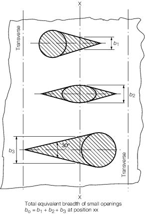
Figure 3.2.3 Isolated openings
2.2.16 Isolated
openings in longitudinals or longitudinal girders need not be deducted
if their depth does not exceed 25 per cent of the web depth or 75
mm, whichever is the lesser.
2.2.17 Openings
are considered isolated if they are spaced more than 1 m apart.
2.2.18 A
reduction for drainage holes and scallops in beams and girder, etc.
is not necessary so long as the global section modulus at deck or
keel is reduced by no more than 0,5 per cent.
2.3 Higher tensile steel
2.3.1 Higher
tensile steel may be used for both deck and bottom structures or deck
structure only. Where fitted for global strength purposes, it is to
be used for the whole of the longitudinally continuous material for
the following vertical distances:
-
z
htd below the line of deck at side
-
z
htb above the top of keel
where
F
D and F
B are not to be taken as less than k
g and are defined in Vol 1, Pt 6, Ch 3, 2.3 Higher tensile steel 2.3.2
z
D, z
B and k
g and are defined in Vol 1, Pt 6, Ch 1, 1.3 Symbols and definitions.
2.3.2 Where
the maximum hull vertical bending stress at the deck or keel is less
than the permissible combined stress, σp, reductions in local
scantlings within to 0,3L
R to 0,7L
R may be permitted. The reduction factors are defined as follows:
-
For hull members
above the neutral axis
-
For hull member
below the neutral axis
where
σD, σB and σws are defined in Vol 1, Pt 6, Ch 1, 1.3 Symbols and definitions 1.3.1.
2.3.3 In general,
the values of σD and σB to be used are
the greater of the sagging or hogging stresses. F
D and F
B are not to be taken as less than 0,67 for plating
and 0,75 for longitudinal stiffeners.
2.4 Longitudinal bending strength
2.4.1 The
effective geometric properties of all critical sections along the
length of the ship are to be calculated directly from the dimensions
of the section using only effective material elements which contribute
to the global longitudinal strength irrespective of the grades of
steel incorporated in the construction, see
Vol 1, Pt 6, Ch 3, 2.2 Section modulus calculation.
2.4.2 Where
higher tensile steel is fitted to satisfy global strength requirements,
the extent of higher tensile steel is to be as specified in Vol 1, Pt 6, Ch 3, 2.3 Higher tensile steel. Where a mix of steel grades is
used for plating and associated stiffeners, then the lower of the
steel grades is to be used for the derivation of permissible stresses.
2.4.3 The
longitudinal strength of the ship is to satisfy the following criteria
for the hogging and sagging conditions:
where
|
σp
|
= |
fσhg
fhts σyd
|
|
fσhg
|
= |
0,75 from 0,3LR to 0,7LR
|
| = |
 for continuous structural members aft of
0,3LR and forward of 0,7LR for continuous structural members aft of
0,3LR and forward of 0,7LR
|
where
|
X
|
= |
longitudinal distance, in metres, from the F.P. for locations within
the forward end region (forward of 0,7LR) and from the A.P. for
locations within the aft end region (aft of 0,3LR) |
|
fσws
|
= |
limiting working stress coefficient |
| = |
1,2 |
Note that the σws criteria may be relaxed if
it can be demonstrated that either:
- A continuous fatigue monitoring system is to be adopted for the
in-service life of the ship; or
- A fatigue design assessment procedure is applied which demonstrates
that a higher limiting working stress coefficient, f
σws, may be applied.
σB, σD and σp are
given in Table 3.2.1
fhts, fσhg, fσws,
MwHog, MwSag, Mtot,
σyd and σydMild are defined in Vol 1, Pt 6, Ch 1, 1.3 Symbols and definitions.
LR is defined in Vol 1, Pt 1, Ch 1, 5.2 Principal particulars.
| Component stress type
|
Nominal stress, N/mm2
|
| Hull girder bending stress at strength deck,
see Note 1
|
|
| Hull girder bending stress at keel, see
Note 1
|
|
| Hull girder bending stress range, see
Note 2
|
|
Note
1. The hogging and bending moments are to
be considered.
Note
2. The stress range at the keel or other
longitudinally effective material should be used if it is greater than
the stress range at the strength deck.
|
2.4.4 The
design stress due to hull girder bending, σhg, for
each structural member is given by:
2.4.5 Where
different grades of steel are used then it should be ensured that
the design stress in each structural member is less than the permissible
hull vertical bending stress, i.e.
2.5 Minimum hull section modulus
2.5.1 The
hull midship section modulus about the transverse neutral axis, at
the deck or the keel, is to be not less than:
2.6 Minimum hull moment of inertia
2.6.1 The
hull midship section moment of inertia about the transverse neutral
axis is to be not less than the following using the maximum total
bending moment, sagging or hogging:
2.7 Shear strength
2.7.1 The
shear strength of the vessel at any position along its length is to
satisfy the following criteria:
where
|
Q
tot
|
= |
is defined in Vol 1, Pt 5, Ch 1, 1.4 Symbols and definitions
|
|
A
τ
|
= |
is defined in Vol 1, Pt 6, Ch 1, 1.3 Symbols and definitions
|
|
τp
|
= |
0,72τyd
|
|
τyd
|
= |
is
defined in Vol 1, Pt 6, Ch 1, 1.3 Symbols and definitions.
|
|