
Section
1 General
1.1 General
1.1.1 The global and local loads detailed in this Part are to be used in
conjunction with the formulae given in Vol 1, Pt 6 Scantling Determination to determine the scantlings of Trimarans.
1.2 Theoretical analysis
1.3 Model experiments
1.4 Symbols and definitions
1.4.1 The
symbols and definitions for use throughout this Part are as follows:
|
a
|
= |
projection
of T
CU forward of the FP, in metres
|
|
a
vmh
|
= |
the vertical acceleration at the centre of the main hull, in
terms of g |
|
a
vsh
|
= |
the vertical acceleration at the centre of the side hull, in
terms of g |
|
b
1
|
= |
projection of T
CU waterline outboard
of the design draught waterline at 0,9L
R from
the AP, in metres
|
|
b
2
|
= |
projection of T
CU waterline outboard
of the design draught waterline at 0,8L
R from
the AP, in metres
|
|
g
|
= |
acceleration
due to gravity, is to be taken as 9,81 m/s2
|
|
x
sh
|
= |
the longitudinal distance, in metres, from midlength of the
side hull to mid-length of the main hull where distance is positive
for side hull mid-length aft of main hull mid-length |
|
x
shaft
|
= |
the longitudinal distance, in metres, from the aft end of L
R to the aft transition point on the main hull where the main
deck extends towards the side hull
|
|
x
shfwd
|
= |
the longitudinal distance, in metres, from the aft end of L
R to the fwd transition point on the main hull where the main
deck connection from the side hull terminates
|
|
x
wl
|
= |
longitudinal distance, in metres, measured forwards from the
aft end of L
wl to the position or centre of
gravity of the item being considered
|
|
y
|
= |
transverse
distance, in metres, from the centreline to the centre of gravity
of the item being considered. y is positive to port and
negative to starboard
|
|
y
cs
|
= |
transverse distance from centreline to the centre of area of
a cross-section A
cs taken at mid-length of
the side hull, see
Figure 1.1.2 Definition of y
cs
|
|
y
sh
|
= |
the distance, in metres between the centreline of the main hull
and the transverse centre of area of the side hull, see
Figure 4.3.1 Splitting moment in Chapter 4
|
|
z
|
= |
vertical
distance, in metres, from the baseline to the position or centre of
gravity of the item under consideration. z is positive
above the baseline
|
|
z
wl
|
= |
distance, in metres of the centroid of the area of plating or
stiffener to the local design waterline |
|
A
LB
|
= |
half the water plane at the design draught in the bow region
of the hull forward of 0,8L
R from the AP.
The AP is to be taken at the aft end of the Rule length, L
R. The design draught is to be taken as T, as
defined in Vol 1, Pt 1, Ch 1, 5.2 Principal particulars
|
|
A
LS
|
= |
half the water plane area at a waterline T
CL of
the stern region of the main hull from the aft end to 0,2L
R forward of the AP
|
|
A
UB
|
= |
half the water plane area at a waterline T
CU of
the bow region of the hull forward of 0,8 L
R from
the AP
|
|
A
US
|
= |
half the water plane area at a waterline T
CU of
the stern region of the main hull from the aft end to 0,2L
R forward of the AP
|
|
F
f
|
= |
the hogging, F
fh, or sagging, F
fs, correction factor based on the amount of bow flare, stern
flare, length and effective buoyancy of the after portion end of the
ship above the waterline, see
Vol 1, Pt 5, Ch 4, 2.4 Vertical wave bending moment 2.4.1
|
|
F
fh
|
= |
the hogging correction factor |
|
F
fs
|
= |
the sagging correction factor |
|
GM
|
= |
metacentric
height for the loading condition under consideration, in metres |
|
P
des
|
= |
design pressure due to static and dynamic load components, in
kN/m2, see Ch 5, Vol 1, Pt 5, Ch 5, 3 Shell envelope, Vol 1, Pt 5, Ch 5, 4 Wet-deck, Vol 1, Pt 5, Ch 5, 5 Weather decks and Vol 1, Pt 5, Ch 5, 6 Inner bottom
|
|
V
cd
|
= |
the volume on the cross-deck structure, in m3, on
one side of the ship. The inside and outside boundaries of the cross-deck
structure are to be taken as the vertical lines extending upward from
points O and I, see
Figure 4.3.1 Splitting moment in Chapter 4
|
|
V
cr
|
= |
two thirds the cruising speed, in knots |
|
V
mhs
|
= |
the volume of the main hull, in m3, which extends
the length of the side hull. The outside boundary of the main hull
is to be taken as a vertical line extending upwards from point O, see
Figure 4.3.1 Splitting moment in Chapter
4
|
|
V
sh
|
= |
the volume of one side hull, in m3. The inside boundary
of the side hull is to be taken as a vertical line extending upward
from the point O, see
Figure 4.3.1 Splitting moment in Chapter 4
|
|
V
sp
|
= |
the greater of the cruising speed or two thirds the sprint speed,
in knots. For ships where it is not required to maintain high speeds
in severe weather then the value of V
sp may
be specially considered
|
|
W
sh
|
= |
the total weight of one side hull, in tonnes, including lightship
weight and deadweight. The inside boundary of the side hull is to
be taken as a vertical line extending upward from the point O, see
Figure 4.3.1 Splitting moment in Chapter 4
|
|
ρ |
= |
water density
in t/m3.
|
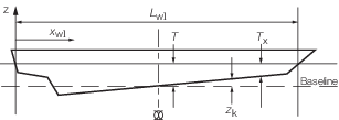
Figure 1.1.1 Definition of draft T and baseline
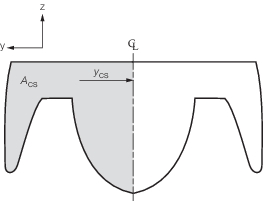
Figure 1.1.2 Definition of y
cs
|