
Section
3 Global cross-deck loads
3.1 Splitting moment
3.1.1 The
splitting moments, for hog, M
sph, and for
sag, M
sps, illustrated in Figure 4.3.1 Splitting moment are to be given by the
following:
   
where
|
|
= |
Points I and O are given in Figure 4.3.2 Distances and locations for splitting loads. Moment values at locations on the cross-deck between
I and O are to be linearly interpolated. If the cross-deck structure
is radiused, points I and O are to be taken as the points where the
tangents lines are at 45° from the horizontal.
|
|
W
hs
|
= |
the total weight of one side hull, in tonnes, including lightship
weight and deadweight, see
Vol 1, Pt 5, Ch 1, 1.4 Symbols and definitions. For preliminary design purposes, this value may be estimated
as a proportion of the total displacement according to the ratio of
the side hull volume to the total volume. This weight is to be calculated
according to the actual weight distribution before final submission
to LR
|
|
f
serv
|
= |
is defined in Vol 1, Pt 5, Ch 4, 2.4 Vertical wave bending moment 2.4.1
|
|
a
z
|
= |
is defined in Vol 1, Pt 5, Ch 3, 2.2 Design accelerations.
The a
rollz component of a
z is
to be calculated at a position y = y
sh
|
|
|
= |
B
mh, B
sh, ∆
and ∆mh are defined in Vol 1, Pt 1, Ch 1, 5.2 Principal particulars.
|
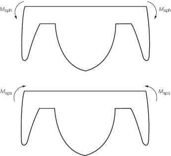
Figure 4.3.1 Splitting moment
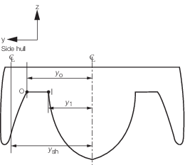
Figure 4.3.2 Distances and locations for splitting loads
3.2 Splitting shear force
3.2.1 The
splitting shear force, Q
sph, corresponding
to the hogging condition and Q
sps, corresponding
to the sagging condition are uniform along the breadth of the cross-deck
structure and are to be calculated as follows:
where
|
W
sh
|
= |
is defined in Vol 1, Pt 5, Ch 4, 3.1 Splitting moment
|
|
f
serv
|
= |
is defined in Vol 1, Pt 5, Ch 4, 2.4 Vertical wave bending moment 2.4.1
|
|
∆
|
= |
is
defined in Vol 1, Pt 1, Ch 1, 5.2 Principal particulars
|
|
a
z
|
= |
is defined in Vol 1, Pt 5, Ch 3, 2.2 Design accelerations.
The a
rollz component of a
z is
to be calculated at a position y =y
sh.
|
3.3 Transverse torsional moment
3.3.1 The
transverse torsional moment, M
tt, as illustrated
in Figure 4.3.3 Transverse torsional moment is uniform along
the breadth of the cross-deck structure and is to be given by the
following:
where
|
L
sh
|
= |
is defined in Vol 1, Pt 1, Ch 1, 5.2 Principal particulars
|
|
|
= |
ρ, V
sh and V
cd are
defined in Vol 1, Pt 5, Ch 1, 1.4 Symbols and definitions
|
|
a
heave
|
= |
is defined in Vol 1, Pt 5, Ch 3, 2.2 Design accelerations
|
|
f
serv
|
= |
is defined in Vol 1, Pt 5, Ch 4, 2.4 Vertical wave bending moment 2.4.1.
|
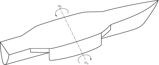
Figure 4.3.3 Transverse torsional moment
|
| Copyright 2022 Clasifications Register Group Limited, International Maritime Organization, International Labour Organization or Maritime
and Coastguard Agency. All rights reserved. Clasifications Register Group Limited, its affiliates and subsidiaries and their respective
officers, employees or agents are, individually and collectively, referred to in this clause as 'Clasifications Register'. Clasifications
Register assumes no responsibility and shall not be liable to any person for any loss, damage or expense caused by reliance
on the information or advice in this document or howsoever provided, unless that person has signed a contract with the relevant
Clasifications Register entity for the provision of this information or advice and in that case any responsibility or liability is
exclusively on the terms and conditions set out in that contract.
|
 |
|