
Section
2 Structural modelling
2.1 Global model
2.1.1 A 3-D
plate element model of the ship is to be used. This model should extend
over the full length, breadth and depth of the ship. In some cases,
a half breadth model may be used with the appropriate symmetrical
boundary conditions. However, to simplify the loading and boundary
conditions, it is recommended that a full breadth model be used.
2.1.2 The
scantlings to be modelled are to be in accordance with those required
by the Rules, as well as those required by the Complementary Rules.
If the Complementary Rules are the Rules and Regulations for
the Classification of Naval Ships (hereinafter referred to
as the Rules for Naval Ships) or the Rules and Regulations for
the Classification of Special Service Craft (hereinafter referred
to as the Rules for Special Service Craft), then these scantlings
are ‘net’ scantlings. If the Complementary Rules are the Rules and Regulations for the Classification of Ships (hereinafter
referred to as the Rules for Ships), the required scantlings are ‘gross’
scantlings. Any additional thicknesses added due to the Enhanced Scantlings
notation are not to be modelled.
2.1.3 The
model should represent, with reasonable accuracy, the actual geometric
shape of the hull. All effective longitudinal material is to be included.
Similarly, all transverse primary structure, i.e. web frames, watertight
and fire divisional bulkheads are to be represented in the model.
The superstructure should also be included in the model.
2.1.4 The
FE model is to be represented using a right handed Cartesian co-ordinate
system, depicted in Figure 2.2.1 FE Co-ordinate system,
where:
-
x is measured
in the longitudinal direction, positive forward from the aft perpendicular
-
y is measured
in the transverse direction, positive to port from the centreline
-
z is measured
in the vertical direction, positive upward from the baseline
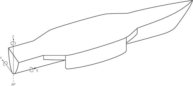
Figure 2.2.1 FE Co-ordinate system
2.1.5 The
size and type of plate elements selected are to provide a satisfactory
representation of the deflection and stress distribution within the
ship's structure. In general, the plate element mesh is to follow
the primary stiffening. Typically, the following guidelines are applicable:
-
Longitudinally,
one element between web frames or intermediate floors, if applicable;
-
Vertically, two
elements between decks, stringers, or every second or third stiffener,
whichever is the smaller distance;
-
Transversely,
at least two elements spanning the cross-deck structure and elsewhere,
sufficient elements to maintain a satisfactory panel aspect ratio.
2.1.6 Plate
elements are to have an aspect ratio less than 3, particularly in
areas of interest in the model.
2.1.7 All
primary structure, such as deck plating, bottom and side shell plating,
longitudinal and transverse bulkhead plating, transverse floors, superstructure
blocks, deckhouse blocks and internal structural walls are to be represented
by plate elements. Primary girders, deep beams, web frames, etc. are
to be represented by at least three elements through the depth of
the member in areas of interest.
2.1.9 Secondary
stiffening members may be modelled using line elements having axial
and bending stiffness (bars). These elements may be grouped as necessary
at the plate boundaries.
2.1.10 Pillars
are to be represented by line elements having axial and bending stiffness.
2.1.11 Shell
openings, deck openings, door openings and window openings of a significant
size are to be represented in the model such that the deformation
pattern under hull torsion, shear and bending loads is adequately
represented in way of critical areas.
2.1.12 The
model is to accurately reflect shell and superstructure side recesses,
sweep brackets and superstructure breaks. The basic mesh, as described
in Vol 4, Pt 1, Ch 2, 2.1 Global model 2.1.5 may need to be further
refined in order to include these features.
2.2 Local models
2.2.1 In general,
detailed stress analysis is to be carried out in the following locations, see also Vol 4, Pt 1, Ch 2, 1.1 Application 1.1.4:
-
The connections
of the side hull to the ends of the cross-deck structure.
-
The connections
of the centre hull to the ends of the cross-deck structure.
-
The transverse
bulkhead where the highest shear stresses has been identified from
the global load cases.
-
Areas with discontinuities
in structure such as in way of openings or at the termination points
of major structure.
-
After reviewing
the results from the global load cases, areas in way of high stress
gradients and areas exceeding the stress criteria specified in Table 2.2.1 Stress acceptance criteria
permissible stresses.
Table 2.2.1 Stress acceptance criteria
permissible stresses
|
|
Permissible stresses
|
|
|
σvm
|
σ
|
τ
|
| Global model, coarse mesh
|
0,9σyd
|
0,75σyd
|
0,35σyd
|
| Fine mesh models, individual element
stresses
|
1,2σyd
|
—
|
—
|
| Fine mesh models, average
stress
|
1,0σyd
|
—
|
—
|
Note
2. σ, τ, are to be taken as membrane
stresses.
Note
3. σvm is to be calculated
based on the membrane shear and direct stresses of the plate element.
Note
4. Average von Mises stress is to be
calculated as the average of the von Mises stresses from the element
being assessed and the elements connected to its boundary nodes.
Averaging is not to be carried across structural discontinuity and
abutting structure.
|
2.2.2 Evaluation
of detailed stresses requires the use of refined finite element mesh
density in way of areas of high stress.
2.2.3 The
extent of the local finite element model is to be such that the calculated
stresses at the areas of interest are not significantly affected by
the imposed boundary conditions and application of loads. The boundary
of the fine mesh model is to coincide with main supporting structural
members.
2.2.4 The
mesh size in the fine mesh regions is not to be greater than 100 mm
x 100 mm. A finer mesh size, such as 50 mm x 50 mm, may be required
dependent on vessel size and the detail being considered. The extent
of the fine mesh region is to be in general not less than 10 elements
in all directions from the area under investigation. A smooth transition
of mesh density is to be maintained.
2.2.5 The
structural geometry, particularly in areas of concern is to be accurately
represented.
|