
Section
2 Cargo tank region
2.1 Symbols
2.1.1 The symbols used in this Chapter are defined as follows:
|
L
|
= |
Rule length, in metres |
|
L2
|
= |
Rule length, L, but need not be taken greater than 300 m |
|
B
|
= |
moulded breadth, in metres |
|
D
|
= |
moulded depth, in metres |
|
TSC
|
= |
deep load draught, in metres |
|
TLT
|
= |
minimum design light load draught, in metres |
|
E
|
= |
modulus of elasticity, in N/mm2
|
|
σyd
|
= |
specified minimum yield stress of the material, in
N/mm2
|
|
τyd
|
= |
 N/mm2 N/mm2
|
|
s
|
= |
stiffener spacing, in mm |
|
p
|
= |
design pressure for the design load set being considered, in
kN/m2
|
|
g
|
= |
acceleration due to gravity, 9,81 m/s2
|
2.2 General
2.2.1
Application.
- The requirements of this Section apply to the hull structure
within the cargo tank region of the ship unit.
2.2.2
Evaluation of scantlings.
- Structural design details are to comply with the requirements
given in Pt 10, Ch 3, 1.7 Standard construction details to Pt 10, Ch 3, 1.12 Local reinforcement.
- The scantlings are to be assessed to ensure that the strength
criteria are satisfied at all longitudinal positions, where applicable.
- Local scantlings are to be increased where applicable to account
for:
- local variations, such as increased spacing or
increased stiffener spans;
- green sea pressure loads;
- fore and aft end strengthening requirements, see Pt 10, Ch 3, 3 Forward of the forward cargo tank and Pt 10, Ch 3, 5 Aft end;
- local deflection requirements to limit interaction
between the hull structure and liquefied gas cargo containment
systems where fitted; and
- in way of anti-roll chocks, anti-flotation chocks and
other similar items where fitted.
- Where the hull structure forms part of, or provides direct
support to, a liquefied gas cargo containment system, the scantlings are to
be sufficient to meet the requirements of the containment system design and
the loads imposed by it. A structural analysis of the hull structure will be
required using direct calculation procedures which are to be agreed with LR
at as early a stage as possible.
- Where a membrane type liquefied gas cargo containment system is
fitted inside the hull, the scantlings of the hull providing direct support
to the containment system are to comply with the requirements in this Part
outlined for cargo tanks and other tanks designed for liquid filling.
However, the tank pressure is to be taken as:
For static load
cases:
P
in-tk + P
o
For dynamic load cases:
P
in-tk + P
in-dyn + P
o
where
P
o is the design vapour pressure defined in Pt 11, Ch 4, 1.1 Definitions 1.1.2.
For the operating and
inspection/maintenance conditions the liquid density is to be taken as
that of the liquefied gas cargo, see Table 2.1.1 Minimum density of
liquid for strength and fatigue assessment.
The design of
membrane tanks is to comply with Pt 11, Ch 4 Cargo Containment.
- Where an independent tank is fitted inside the hull, the
scantlings of the hull structure surrounding, but not forming, part of the
independent tank are to be as required for watertight boundaries. The
scantlings of independent tanks are to comply with Pt 11, Ch 4 Cargo Containment.
2.2.3
General scantling requirements.
- The hull structure is to comply with the applicable
requirements of:
- hull girder longitudinal strength, see
Pt 10, Ch 3, 1 Scantling requirements;
- strength against sloshing and impact loads, see
Pt 10, Ch 3, 6 Evaluation of structure for sloshing and impact loads;
- hull girder ultimate strength, see LR ShipRight
Procedure for Ship Units;
- strength assessment (FEM), see LR ShipRight
Procedure for Ship Units;
- fatigue strength, see LR ShipRight Procedure for
Ship Units;
- buckling, see Pt 10, Ch 1, 17 Buckling.
- The net section modulus, shear areas and other sectional
properties of the local and primary support members are to be determined in
accordance with Pt 10, Ch 1, 12 Corrosion additions.
2.2.4
Minimum thickness for plating and local support members.
- The thickness of plating and stiffeners in the cargo tank
region is to comply with the appropriate minimum thickness requirements
given in Table 3.2.1 Minimum net
thickness for plating and local support members in the cargo tank
region.
Table 3.2.1 Minimum net
thickness for plating and local support members in the cargo tank
region
|
|
Scantling location
|
Net
thickness (mm)
|
| Plating
|
Shell
|
Keel plating
|
6,0 + 0,04L2
|
| Bottom shell/bilge/side shell
|
4,5 + 0,03L2
|
| Upper deck
|
4,5 + 0,02L2
|
| Other
structure
|
Hull internal tank boundaries
|
4,5 + 0,02L2
|
| Non-tight bulkheads, bulkheads between dry
spaces and other plates in general
|
4,5 + 0,01L2
|
| Local
support members
|
Local support members on
tight boundaries
|
3,5 + 0,015L2
|
| Local support members on
other structure
|
2,5 + 0,015L2
|
| Tripping brackets
|
5,0 + 0,015L2
|
2.2.5
Minimum thickness for primary support members.
- The thickness of web plating and face plating of primary
support members in the cargo tank region is to comply with the appropriate
minimum thickness requirements given in Table 3.2.2 Minimum net
thickness for primary support members in cargo tank region.
Table 3.2.2 Minimum net
thickness for primary support members in cargo tank region
| Scantling
location
|
Net thickness (mm)
|
| Bottom centreline girder
|
5,5 + 0,025L2
|
| Other bottom girders
|
5,5 + 0,02L2
|
| Bottom floors, web plates of side transverses and
stringers in double hull
|
5,0 + 0,015L2
|
| Web and flanges of vertical web frames on longitudinal
bulkheads, horizontal stringers on transverse bulkhead,
deck transverses (above and below upper deck) and cross
ties
|
5,5 + 0,015L2
|
2.3 Hull envelope plating
2.3.1
Keel plating.
- Keel plating is to extend over the flat of
bottom for the complete length of the ship unit. The breadth,
bkl
, is not to be less than:
- The thickness of the keel plating is to comply with the
requirements given in Pt 10, Ch 3, 2.3 Hull envelope plating 2.3.2.
2.3.2
Bottom shell plating.
- The thickness of the bottom shell plating is
to comply with the requirements in Table 3.2.3 Thickness
requirements for plating.
Table 3.2.3 Thickness
requirements for plating
The minimum net thickness, tnet
, is to be taken as the greatest value for all
applicable design load sets, as given in Table 3.2.6 Design load sets
for plating and local support members (see continuation), and given by
|
tnet
|
= |
 mm mm |
|
| Acceptance criteria set
|
Structural member
|
βa
|
αa
|
Ca-max
|
| AC1
|
Longitudinal strength
members
|
Longitudinally stiffened plating
|
0,9
|
0,5
|
0,8
|
| Transversely or vertically stiffened
plating
|
0,9
|
1,0
|
0,8
|
| Other members
|
0,8
|
0
|
0,8
|
| AC2
|
Longitudinal strength
members
|
Longitudinally stiffened plating
|
1,05
|
0,5
|
0,95
|
| Transversely or vertically stiffened
plating
|
1,05
|
1,0
|
0,95
|
| Other members,
including watertight boundary plating
|
1,0
|
0
|
1,0
|
| AC3
|
All members
|
1,0
|
0
|
1,0
|
where
|
αp
|
= |
correction factor for the panel
aspect ratio |
| = |
 but is not to be taken as
greater than 1,0 but is not to be taken as
greater than 1,0 |
|
lp
|
= |
length of plate panel, to be
taken as the spacing of primary support members,
S, unless carlings are fitted, in metres |
|
Ca
|
= |
permissible bending stress
coefficient for the design load set being
considered |
| = |
 but not to be taken greater
than Ca–max but not to be taken greater
than Ca–max
|
|
|
σhg
|
= |
hull girder bending stress for the
design load set being considered and calculated at
the load calculation point |
| = |
 N/mm2 N/mm2
|
|
Mv-total
|
= |
design vertical bending moment at
the longitudinal position under consideration for
the design load set being considered, in kNm. The
still water bending moment, Msw-perm
, is to be taken with the same sign as the
simultaneously acting wave bending moment,
Mwv
|
|
Mh-total
|
= |
design horizontal bending moment
at the longitudinal position under consideration
for the design load set being considered, in
kNm |
|
Iv-net50
|
= |
net vertical hull girder moment
of inertia, at the longitudinal position being
considered, in m4
|
|
Ih-net50
|
= |
net horizontal hull girder moment
of inertia, at the longitudinal position being
considered, in m4
|
|
y
|
= |
transverse coordinate of load
calculation point, in metres |
|
z
|
= |
vertical coordinate of the load
calculation point under consideration, in
metres |
|
zNA-net50
|
= |
distance from the baseline to the
horizontal neutral axis, in metres |
|
2.3.3
Bilge plating.
- The thickness of bilge plating is not to be less than that
required for the adjacent bottom shell, see
Pt 10, Ch 3, 2.3 Hull envelope plating 2.3.2.(a), or adjacent side shell plating, see
Pt 10, Ch 3, 2.3 Hull envelope plating 2.3.4.(a), whichever is the greater.
- The net thickness of bilge plating, tnet
, without longitudinal stiffening is not to be less than:
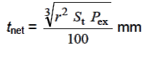
where
|
r
|
= |
effective bilge radius |
| = |
r0
+ 0,5 (a + b) mm |
|
St
|
= |
distance between transverse stiffeners, webs or
bilge brackets, in metres |
Where the plate seam is located in the flat plate just
below the lowest stiffener on the side shell, any increased thickness
required for the bilge plating does not have to extend to the adjacent
plate above the bilge, provided that the plate seam is not more than
Sb
/4 below the lowest side longitudinal. Similarly, for flat part of
adjacent bottom plating, any increased thickness for the bilge plating
does not have to be applied, provided that the plate seam is not more
than Sa
/4 beyond the outboard bottom longitudinal. Regularly
longitudinally-stiffened bilge plating is to be assessed as a stiffened
plate. The bilge keel is not considered as ‘longitudinal stiffening’ for
the application of this requirement.

Figure 3.2.1 Unstiffened bilge
plating
- Where bilge longitudinals are omitted, the bilge plate
thickness outside 0,4L amidships will be considered in relation to
the support derived from the hull form and internal stiffening arrangements.
In general, outside 0,4L amidships the bilge plate scantlings and
arrangement are to comply with the requirements of ordinary side or bottom
shell plating in the same region. Consideration is to be given where there
is increased loading in the forward region, see also
Pt 10, Ch 3, 6.4 Bottom and bilge slamming 6.4.9.
2.3.4
Side shell plating.
- The thickness of the side shell plating is
to comply with the requirements in Table 3.2.3 Thickness
requirements for plating.
- The net thickness, tnet
, of the side plating within the range as specified in Pt 10, Ch 3, 2.3 Hull envelope plating 2.3.4.(c) is not to be less than:
|
tnet
|
= |
 mm mm |
- The thickness in Pt 10, Ch 3, 2.3 Hull envelope plating 2.3.4.(b) is to be applied to the following extent of the side
shell plating, see Figure 3.2.2 Extent of side
shell plating:
- longitudinal extent:
- between a section aft of amidships where the
breadth at the waterline exceeds 0,9B, and a section
forward of amidships where the breadth at the waterline
exceeds 0,6B.
- vertical extent:
- between 300 mm below the minimum design
waterline at the light load draught, TLT
, amidships to 0,25TSC
or 2,2 m, whichever is greater, above the draught
TSC
.

Figure 3.2.2 Extent of side
shell plating
2.3.5
Sheerstrake.
- The sheerstrake is to comply with the requirements in Pt 10, Ch 3, 2.3 Hull envelope plating 2.3.4.
- The welding of deck fittings to rounded sheerstrakes is to be
avoided within 0,6L of amidships.
- Where the sheerstrake extends above the deck stringer plate,
the top edge of the sheerstrake is to be kept free from notches and isolated
welded fittings, and is to be smooth with rounded edges. Grinding may be
required if the cutting surface is not smooth. Drainage openings with a
smooth transition in the longitudinal direction may be permitted.
2.4 Hull envelope framing
2.4.1
General.
- The bottom shell, inner bottom and deck are to be
longitudinally framed in the cargo tank region. The side shell, inner hull
bulkheads and longitudinal bulkheads are generally to be longitudinally
framed. Suitable alternatives which take account of resistance to buckling
will be specially considered.
- Where longitudinals are omitted in way of
the bilge, a longitudinal is to be fitted at the bottom and at the side,
close to the position where the curvature of the bilge plate starts. The
distance between the lower turn of bilge and the outermost bottom
longitudinal, a, is generally not to be greater than one third of
the spacing between the two outermost bottom longitudinals, sa
. Similarly, the distance between the upper turn of the bilge and the
lowest side longitudinal, b, is generally not to be greater than one
third of the spacing between the two lowest side longitudinals,
sb
. See Figure 3.2.1 Unstiffened bilge
plating.
2.4.2
Scantling criteria.
- The section modulus and thickness of the hull envelope framing
are to comply with the requirements given in Table 3.2.4 Section modulus
requirements for stiffeners and Table 3.2.5 Web thickness
requirements for stiffeners.
Table 3.2.4 Section modulus
requirements for stiffeners
| The minimum net section modulus,
Znet
, is to be taken as the greatest value calculated
for all applicable design load sets, as given in Table 3.2.6 Design load sets
for plating and local support members (see continuation), and given by:

where
|
fbdg
|
= |
bending moment factor: |
| = |
12 for horizontal stiffeners |
| = |
for continuous stiffeners and
where end connections are fitted consistent with
idealisation of the stiffener as having as fixed
ends: |
| = |
10 for vertical stiffeners
for stiffeners with reduced end
fixity, see
Table 3.7.2 Values of fbdg and
fshr
|
|
lbdg
|
= |
effective bending span, in
metres |
|
Cs
|
= |
permissible bending stress
coefficient for the design load set being
considered, to be taken as: |
|
| Sign of hull girder bending stress,
σhg
|
Side pressure acting on
|
Acceptance criteria
|
| Tension (+ve)
|
Stiffener side
|
|
Cs
|
= |

|
but not to be taken greater than
Cs-max
|
| Compression (-ve)
|
Plate side
|
| Tension (+ve)
|
Plate side
|
|
| Compression (-ve)
|
Stiffener side
|
|
|
| Acceptance criteria set
|
Structural member
|
βs
|
αs
|
Cs-max
|
| AC1
|
Longitudinal strength member
|
0,85
|
1,0
|
0,75
|
| Transverse or vertical member
|
0,75
|
0
|
0,75
|
| AC2
|
Longitudinal strength member
|
1,0
|
1,0
|
0,9
|
| Transverse or vertical member
|
0,9
|
0
|
0,9
|
| Watertight boundary stiffeners
|
0,9
|
0
|
0,9
|
| AC3
|
All members
|
1,0
|
0
|
1,0
|
|
σhg
|
= |
hull girder bending stress for
the design load set being considered and
calculated at the reference point |
| = |
 N/mm2 N/mm2
|
|
| Stiffener
location
|
Msw-perm
|
| Pressure acting on plate
side
|
Pressure
acting on stiffener side
|
| Above neutral axis
|
Sagging SWBM
|
Hogging
SWBM
|
| Below neutral axis
|
Hogging SWBM
|
Sagging
SWBM
|
|
Mh-total
|
= |
design horizontal bending moment
at longitudinal position under consideration for
the design load set being considered, in kNm |
|
Iv-net50
|
= |
net vertical hull girder moment
of inertia, at the longitudinal position being
considered, in m4
|
|
Ih-net50
|
= |
net horizontal hull girder moment
of inertia, at the longitudinal position being
considered, in m4
|
|
y
|
= |
transverse coordinate of the
reference point, in metres |
|
z
|
= |
vertical coordinate of the
reference point, in metres |
|
zNA-net50
|
= |
distance from the baseline to the
horizontal neutral axis, in metres |
|
Table 3.2.5 Web thickness
requirements for stiffeners
The minimum net web
thickness, tw-net
, is to be taken as the greatest value calculated
for all applicable design load sets, as given in Table 3.2.6 Design load sets
for plating and local support members (see continuation), and given by
|
tw–net
|
= |
 mm mm |
where
|
fshr
|
= |
shear force distribution factor:
for continuous stiffeners and where
end connections are fitted consistent with
idealisation of the stiffener as having as fixed
ends:
|
| = |
0,5 for horizontal
stiffeners |
| = |
0,7 for vertical stiffeners
for stiffeners with reduced end
fixity, see Table 3.7.2 Values of fbdg and
fshr
|
|
dshr
|
= |
effective shear depth, in mm |
|
Ct
|
= |
permissible shear stress
coefficient for the design load set being
considered, to be taken as |
| = |
0,75 for acceptance criteria set
AC1 |
| = |
0,90 for acceptance criteria set
AC2 |
| = |
1,0 for acceptance criteria set
AC3 |
|
2.5 Inner bottom
2.5.1
Inner bottom plating.
- The thickness of the inner bottom plating is to comply with the
requirements given in Table 3.2.3 Thickness
requirements for plating.
- In way of a welded hopper knuckle, the inner bottom is to be
scarphed to ensure adequate load transmission to surrounding structure and
reduce stress concentrations.
- In way of corrugated bulkhead stools, where fitted, particular
attention is to be given to the through thickness properties, and
arrangements for continuity of strength, at the connection of the bulkhead
stool to the inner bottom.
2.6 Bulkheads
2.6.1
General.
- The inner hull and longitudinal bulkheads are generally to be
longitudinally framed, and plane. Corrugated bulkheads are to comply with
the requirements given in Pt 10, Ch 3, 2.6 Bulkheads 2.6.6.
- Where bulkheads are penetrated by cargo or ballast piping, the
structural arrangements in way are to be adequate for the loads imparted to
the bulkheads by the hydraulic forces in the pipes.
2.6.2
Longitudinal tank boundary bulkhead plating.
- The thickness of the longitudinal tank boundary bulkhead plating
is to comply with the requirements given in Table 3.2.3 Thickness
requirements for plating.
- Inner hull and longitudinal bulkheads are to extend as far
forward and aft as practicable and are to be effectively scarphed into the
adjoining structure.
2.6.3
Hopper side structure.
- Knuckles in the hopper tank plating are to be supported by side
girders and stringers, or by a deep longitudinal.
2.6.6
Corrugated bulkheads.
- In general, corrugated bulkheads are to be designed with the
corrugation angles, φ, between 55° and 90°, see
Figure 3.2.3 Definition of
parameters for corrugated bulkhead (units with longitudinal bulkhead
at centreline).

Figure 3.2.3 Definition of
parameters for corrugated bulkhead (units with longitudinal bulkhead
at centreline)
- The global strength of corrugated bulkheads, lower stools and
upper stools, where fitted, and attachments to surrounding structures are to
be verified with the cargo tank FEM model, in accordance with the LR
ShipRight Procedure for Ship Units, in the midship region. The global
strength of corrugated bulkheads outside of midship region is to be
considered, based on results from the cargo tank FEM model and using the
appropriate pressure for the bulkhead being considered. Additional FEM
analysis of cargo tank bulkheads forward and aft of the midship region may
be necessary if the bulkhead geometry, structural details and support
arrangement details differ significantly from bulkheads within the mid cargo
tank region.
- The net thicknesses, tnet
, of the web and flange plates of corrugated bulkheads are to be taken
as the greatest value calculated for all applicable design load sets, as
given in Table 3.2.6 Design load sets
for plating and local support members (see continuation), and given by
|
tnet
|
= |
 mm mm |
where
|
Ca
|
= |
permissible bending stress coefficient |
| = |
0,75 for acceptance criteria set AC1 |
| = |
0,90 for acceptance criteria set AC2 |
| = |
1,0 for acceptance criteria set AC3. |
- Where the corrugated bulkhead is built with
flange and web plate of different thickness, the thicker net plating
thickness, tm-net
, is to be taken as the greatest value calculated for all applicable
design load sets, as given in Table 3.2.6 Design load sets
for plating and local support members (see continuation), and given by:
|
tm–net
|
= |
 mm mm |
where
|
tn-net
|
= |
net thickness of the thinner plating, either flange
or web, in mm |
|
bp
|
= |
breadth of thicker plate, either flange or web, in
mm |
|
Ca
|
= |
permissible bending stress coefficient |
| = |
0,75 for acceptance criteria set AC1 |
| = |
0,90 for acceptance criteria set AC2 |
| = |
1,0 for acceptance criteria set AC3. |
2.6.7
Vertically corrugated bulkheads.
- In addition to the requirements of Pt 10, Ch 3, 2.6 Bulkheads 2.6.6, vertically corrugated bulkheads are also to comply with
the following requirements.
- The net plate thicknesses as required by
Pt 10, Ch 3, 2.6 Bulkheads 2.6.7.(e) and Pt 10, Ch 3, 2.6 Bulkheads 2.6.7.(f) are to be maintained for two thirds of the corrugation
length, lcg
, from the lower end, where lcg
is as defined in Pt 10, Ch 3, 2.6 Bulkheads 2.6.7.(c). Above that, the net plate thickness may be reduced by
20 per cent.
- Where a lower stool is fitted, the net web
plating thickness of the lower 15 per cent of the corrugation,
tw-net
, is to be taken as the greatest value calculated for all applicable
design load sets from Table 3.2.6 Design load sets
for plating and local support members (see continuation).
|
tw-net
|
= |
 mm mm |
where
|
Qcg
|
= |
design shear force imposed on the web plating at
the lower end of the corrugation |
| = |
 kN kN |
|
P1
|
= |
design pressure for the design load set being
considered, calculated at the lower end of the corrugation, in
kN/m2
|
|
Pu
|
= |
design pressure for the design load set being
considered, calculated at the upper end of the corrugation, in
kN/m2
|
|
Ct-cg
|
= |
permissible shear stress coefficient |
| = |
0,75 for acceptance criteria set AC1 |
| = |
0,90 for acceptance criteria set AC2 |
| = |
for acceptance criteria set AC3. |
Table 3.2.6 Design load sets
for plating and local support members (see continuation)
| Structural member
|
Space type
|
Operation on
site
|
Inspection/maintenance
|
Transit
|
Flooded
|
| Draught
|
S
|
S+D
|
Draught
|
S
|
S+D
|
Draught
|
S
|
S+D
|
Draught
|
S
|
S+D
|
| Load
|
Load
|
Load
|
Load
|
Load
|
Load
|
Load
|
Load
|
| EXTERNAL
MEMBERS
|
Acceptance
criteria
|
|
AC1
|
AC2
|
|
AC1
|
AC2
|
|
AC1
|
AC2
|
|
AC2
|
AC3
|
|
|
Exposed deck
|
Space above deck
|
Green sea
|
Deep load
|
|
Pex
|
Deep load
|
|
Pex
|
Deep load
|
|
Pex
|
Flooded
|
|
Pex
|
|
|
Space below deck
|
Tanks designed for liquid filing
|
Light load
Deep load
|
Pin
|
Pin
|
Light load
Deep load
|
Pin
|
Pin
|
Light load
Deep load
|
Pin
|
Pin
|
|
|
|
|
|
Watertight boundaries/Void space
|
|
|
|
Light load
Deep load
|
Pin
|
Pin
|
|
|
|
|
|
|
|
|
Dry
spaces
|
|
|
|
|
|
|
|
|
|
|
|
|
|
|
Bilge, side shell, sheerstrake
|
External sea
|
Sea
water
|
Deep load
|
Pex
|
Pex
|
Deep load
|
Pex
|
Pex
|
Deep load
|
Pex
|
Pex
|
Flooded
|
Pex
|
Pex
|
|
|
Inboard space
|
Tanks designed for liquid filling
|
Light load
Deep load
|
Pin
|
Pin
|
Light load
Deep load
|
Pin
|
Pin
|
Light load
Deep load
|
Pin
|
Pin
|
|
|
|
|
|
Watertight boundaries/Void space
|
|
|
|
Light load
Deep load
|
Pin
|
Pin
|
|
|
|
|
|
|
|
|
Dry
spaces
|
|
|
|
|
|
|
|
|
|
|
|
|
|
|
Keel, bottom shell
|
External sea
|
Sea
water
|
Deep load
|
Pex
|
Pex
|
Deep load
|
Pex
|
Pex
|
Deep load
|
Pex
|
Pex
|
Flooded
|
Pex
|
Pex
|
|
|
Space above the panel
|
Tanks designed for liquid filling
|
Light load
Deep load
|
Pin
|
Pin
|
Light load
Deep load
|
Pin
|
Pin
|
Light load
Deep load
|
Pin
|
Pin
|
|
|
|
|
|
Watertight boundaries/Void space
|
|
|
|
Light load
Deep load
|
Pin
|
Pin
|
|
|
|
|
|
|
|
|
Dry
spaces
|
Light load
Deep load
|
Pdk
|
Pdk
|
Light load
Deep load
|
Pdk
|
Pdk
|
Light load
Deep load
|
Pdk
|
Pdk
|
|
|
|
| INTERNAL
MEMBERS
|
Inner decks, inner bottom tanktops
|
Space above deck
|
Tanks designed for liquid filling
|
Light load
Deep load
|
Pin
|
Pin
|
Light load
Deep load
|
Pin
|
Pin
|
Light load
Deep load
|
Pin
|
Pin
|
Flooded
|
Pin
|
Pin
|
|
|
Watertight boundaries/void space
|
|
|
|
Light load
Deep load
|
Pin
|
Pin
|
|
|
|
Flooded
|
Pin
|
Pin
|
|
|
Dry spaces
|
Light load
Deep load
|
Pdk
|
Pdk
|
Light load
Deep load
|
Pdk
|
Pdk
|
Light load
Deep load
|
Pdk
|
Pdk
|
Flooded
|
Pdk
+Pin
|
Pdk
+Pin
|
|
|
Space below deck
|
Tanks designed for liquid filling
|
Light load
Deep load
|
Pin
|
Pin
|
Light load
Deep load
|
Pin
|
Pin
|
Light load
Deep load
|
Pin
|
Pin
|
Flooded
|
Pin
|
Pin
|
|
|
Watertight boundaries/void space
|
|
|
|
Light load
Deep load
|
Pin
|
Pin
|
|
|
|
Flooded
|
Pin
|
Pin
|
|
|
Dry spaces
|
|
|
|
|
|
|
|
|
|
Flooded
|
Pin
|
Pin
|
|
|
Bilge, side shell, sheerstrake
|
Outboard space
|
Tanks designed for liquid filling
|
Light load
Deep load
|
Pin
|
Pin
|
Light load
Deep load
|
Pin
|
Pin
|
Light load
Deep load
|
Pin
|
Pin
|
Flooded
|
Pin
|
Pin
|
|
|
Watertight boundaries/void space
|
|
|
|
Light load
Deep load
|
Pin
|
Pin
|
|
|
|
Flooded
|
Pin
|
Pin
|
|
|
Dry spaces
|
|
|
|
|
|
|
|
|
|
Flooded
|
Pin
|
Pin
|
|
|
Inboard space
|
Tanks designed for liquid filling
|
Light load
Deep load
|
Pin
|
Pin
|
Light load
Deep load
|
Pin
|
Pin
|
Light load
Deep load
|
Pin
|
Pin
|
Flooded
|
Pin
|
Pin
|
|
|
Watertight boundaries/void space
|
|
|
|
Light load
Deep load
|
Pin
|
Pin
|
|
|
|
Flooded
|
Pin
|
Pin
|
|
|
Dry spaces
|
|
|
|
|
|
|
|
|
|
Flooded
|
Pin
|
Pin
|
| INTERNAL MEMBERS
|
Transverse bulkheads
|
Space forward of bulkhead
|
Tanks designed for liquid
|
Light load
Deep load
|
Pin
|
Pin
|
Light load
Deep load
|
Pin
|
Pin
|
Light load
Deep load
|
Pin
|
Pin
|
Flooded
|
Pin
|
Pin
|
| Watertight boundaries/void space
|
|
|
|
Light load
Deep load
|
Pin
|
Pin
|
|
|
|
Flooded
|
Pin
|
Pin
|
| Dry spaces
|
|
|
|
|
|
|
|
|
|
Flooded
|
Pin
|
Pin
|
| Space aft of bulkhead
|
Tanks designed for liquid filling
|
Light load
Deep load
|
Pin
|
Pin
|
Light load
Deep load
|
Pin
|
Pin
|
Light load
Deep load
|
Pin
|
Pin
|
Flooded
|
Pin
|
Pin
|
| Watertight boundaries/void space
|
|
|
|
Light load
Deep load
|
Pin
|
Pin
|
|
|
|
Flooded
|
Pin
|
Pin
|
| Dry spaces
|
|
|
|
|
|
|
|
|
|
Flooded
|
Pin
|
Pin
|
| NOTES
1. When the unit’s
configuration cannot be described by Table 3.2.6 Design load sets
for plating and local support members (see continuation), the applicable
Design Load Sets to determine the scantling
requirements of structural boundaries are to be
selected so as to specify a full tank on one side
with the adjacent tank or space empty. The boundary
is to be evaluated for loading from both sides.
Design Load Sets are to be selected based on the
tank or space contents, and are to maximise the
pressure on the structural boundary. The applicable
draught is to be taken in accordance with the Design
Load Set and this Table. Design Load Sets covering
the S and S+D design load combinations are to be
selected.
2. Load cases for
exposed decks are to consider any other distributed
or concentrated loads, whereby simultaneously
occurring green sea pressure may be ignored. Load
cases for internal decks are to consider any other
distributed or concentrated loads when green sea
pressure is not applicable.
3.
Ship motion parameters of GM and kr
are to be selected according to the loading
condition.
4. Light load draught
to be taken as the minimum for the load scenario
under consideration (Operation,
Inspection/maintenance, Transit). The minimum
draught may vary between load scenarios.
5. Deep load draught to be taken as the
maximum for the load scenario under consideration
(Operation, Inspection/maintenance, Transit). The
maximum draught may vary between load scenarios.
6. Draughts for flooded
conditions to be taken as the deepest flooded
draught in way of compartment under assessment.
7. Under the assumption that the
ship unit is at sea, external sea pressure will
always be present. Therefore, the design load set to
assess the external shell envelope when the dominant
load direction is from inside the hull outwards may
be taken as Pin
-Pex
.
|
- The depth of the corrugation,
dcg
, is not to be less than:
|
dcg
|
= |
 mm mm |
where
- Where a lower stool is fitted, the net
thickness of the lower two thirds of the flanges of corrugated bulkheads,
tf-net
, is to be taken as the greatest value calculated for all applicable
design load sets, as given in Table 3.2.6 Design load sets
for plating and local support members (see continuation).
|
tf-net
|
= |
 mm mm |
where
|
σbdg-max
|
= |
maximum vertical bending stress in the flange. The
bending stress is to be calculated at the lower end and at the
midspan of the corrugation length |
| = |
 N/mm2 N/mm2
|
|
Zcg-act-net
|
= |
actual net section modulus at the lower end and at
the mid length of the corrugation, in cm3
|
|
Cf
|
= |
coefficient |
| = |

|
- Where a lower stool is fitted, the net
section modulus at the lower and upper ends and at the mid length of the
corrugation, Zcg-net
, is to be taken as the greatest value calculated for all applicable
design load sets, as given in Table 3.2.6 Design load sets
for plating and local support members (see continuation).
|
Zcg-net
|
= |
 cm3 cm3
|
where
|
Mcg
|
= |
 kNm kNm |
|
P
|
= |
 kN/m3 kN/m3
|
|
Pl, Pu
|
= |
design pressure for the design load set being
considered, calculated at the lower and upper ends of the
corrugation, respectively, in kN/m2: for transverse
corrugated bulkheads, the pressures are to be calculated at a
section located at btk
/2 from the longitudinal bulkheads of each tank
for longitudinal corrugated bulkheads, the
pressures are to be calculated at the ends of the tank, i.e.
the intersection of the forward and aft transverse bulkheads
and the longitudinal bulkhead
|
|
btk
|
= |
maximum breadth of tank under consideration measured
at the bulkhead, in metres |
|
Cs-cg
|
= |
permissible bending stress coefficient at middle of
the corrugation length, lcg
|
| = |
ce
, but not to be taken as greater than 0,75 for acceptance
criteria set AC1 |
| = |
ce
, but not to be taken as greater than 0,90 for acceptance
criteria set AC2 |
| = |
ce
, but not to be taken as greater than 1,0 for acceptance
criteria set AC3
at the lower and upper ends of
corrugation length, lcg
|
| = |
0,75 for acceptance criteria set AC1 |
| = |
0,90 for acceptance criteria set AC2 |
| = |
1,0 for acceptance criteria set AC3 |
|
ce
|
= |
 for β ≥ 1,25 for β ≥ 1,25 |
| = |
1,0 for β < 1,25 |
|
β |
= |

|
|
tf-net
|
= |
net thickness of the corrugation flange, in
mm. |
Table 3.2.7 Values of
Ci
| Bulkhead
|
At
lower end of lcg
|
At
mid length of lcg
|
At
upper end of lcg
|
| Transverse
bulkhead
|
C1
|
Cm1
|
0,80Cm1
|
| Longitudinal
bulkhead
|
C3
|
Cm3
|
0,65Cm3
|
| where
|
|
c1
|
= |
 but is not to be taken as less
than 0,60 but is not to be taken as less
than 0,60 |
|
|
a1
|
= |

|
|
|
b1
|
= |

|
|
|
Cm1
|
= |
 but is not to be taken as less
than 0,55 but is not to be taken as less
than 0,55 |
|
|
am1
|
= |

|
|
|
bm1
|
= |

|
|
|
C3
|
= |
 but is not to be taken as less
than 0,60 but is not to be taken as less
than 0,60 |
|
|
a3
|
= |

|
|
|
b3
|
= |

|
|
|
Cm3
|
= |
 but is not to be taken as less
than 0,55 but is not to be taken as less
than 0,55 |
|
|
am3
|
= |

|
|
|
bm3
|
= |

|
|
|
Rbt
|
= |
 for transverse bulkheads for transverse bulkheads |
|
|
Rbl
|
= |
 for longitudinal bulkheads for longitudinal bulkheads |
|
|
Adt
|
= |
cross-sectional area enclosed by
the moulded lines of the transverse bulkhead upper
stool, in m2
|
| = |
0 if no upper stool is
fitted |
| = |
|
|
|
Adl
|
= |
cross-sectional area enclosed by
the moulded lines of the longitudinal bulkhead
upper stool, in m2
|
| = |
0 if no upper stool is fitted |
|
|
Abt
|
= |
cross-sectional area enclosed by
the moulded lines of the transverse bulkhead lower
stool, in m2
|
|
|
Abl
|
= |
cross-sectional area enclosed by
the moulded lines of the longitudinal bulkhead
lower stool, in m2
|
|
|
|
|
|
|
|
|
|
|
|
|
|
|
|
|
|
- For tanks with effective sloshing breadth, bslh
, greater than 0,56B or effective sloshing length
lslh
, greater than 0,13L, additional sloshing analysis is to be
carried out to assess the section modulus of the unit corrugation.
- For ship units with a moulded depth equal to or greater than 16
m, a lower stool is to be fitted in compliance with the following
requirements:
- general:
- the height and depth are not to be less than the
depth of the corrugation;
- the lower stool is to be fitted in line with
the double bottom floors or girders;
- the side stiffeners and vertical webs
(diaphragms) within the stool structure are to align with
the structure below, as far as is practicable, to provide
appropriate load transmission to structures within the
double bottom.
- stool top plating:
- the net thickness of the stool top plate is not
to be less than that required for the attached corrugated
bulkhead and is to be of at least the same material yield
strength as the attached corrugation;
- the extension of the top plate beyond the
corrugation is not to be less than the as-built flange
thickness of the corrugation.
- stool side plating and internal structure:
- within the region of the corrugation depth from
the stool top plate, the net thickness of the stool side
plate is not to be less than 90 per cent of that required by
Pt 10, Ch 3, 2.6 Bulkheads 2.6.7.(b) for the corrugated bulkhead flange at
the lower end and is to be of at least the same material
yield strength;
- the net thickness of the stool side plating and
the net section modulus of the stool side stiffeners is not
to be less than that required by Pt 10, Ch 3, 2.6 Bulkheads 2.6.2, Pt 10, Ch 3, 2.6 Bulkheads 2.6.4 and Pt 10, Ch 3, 2.6 Bulkheads 2.6.5 for transverse or longitudinal bulkhead
plating and stiffeners;
- the ends of stool side vertical stiffeners are
to be attached to brackets at the upper and lower ends of
the stool;
- continuity is to be maintained, as far as
practicable, between the corrugation web and supporting
brackets inside the stool. The bracket net thickness is not
to be less than 80 per cent of the required thickness of the
corrugation webs and is to be of at least the same material
yield strength;
- scallops in the diaphragms in way of the
connections of the stool sides to the inner bottom and to
the stool top plate are not permitted.
- For ship units with a moulded depth less than 16 m, the lower
stool may be eliminated, provided the following requirements are complied
with:
- general:
- Double bottom floors or girders are to be fitted
in line with the corrugation flanges for transverse or
longitudinal bulkheads, respectively;
- brackets/carlings are to be fitted below the
inner bottom and hopper tank in line with corrugation webs.
Where this is not practicable, gusset plates with shedder
plates are to be fitted, see Pt 10, Ch 3, 2.6 Bulkheads 2.6.7.(i).(iii) below and Figure 3.2.3 Definition of
parameters for corrugated bulkhead (units with longitudinal bulkhead
at centreline);
- the corrugated bulkhead and its supporting
structure are to be assessed by Finite Element (FE)
analysis, in accordance with the LR ShipRight Procedure for
Ship Units. In addition, the local scantlings requirements
of Pt 10, Ch 3, 2.6 Bulkheads 2.6.6.(c) and Pt 10, Ch 3, 2.6 Bulkheads 2.6.6.(d) and the minimum corrugation depth
requirement of Pt 10, Ch 3, 2.6 Bulkheads 2.6.7.(d) are to be applied.
- Inner bottom and hopper tank plating:
- The inner bottom and hopper tank in way of the
corrugation are to be of at least the same material yield
strength as the attached corrugation.
- Supporting structure:
- Within the region of the corrugation depth
below the inner bottom, the net thickness of the supporting
double bottom floors or girders is not to be less than the
net thickness of the corrugated bulkhead flange at the lower
end, and is to be of at least the same material yield
strength;
- the upper ends of vertical stiffeners on
supporting double bottom floors or girders are to be
bracketed to adjacent structure;
- brackets/carlings arranged in line with the
corrugation web are to have a depth of not less than 0,5
times the corrugation depth and a net thickness not less
than 80 per cent of the net thickness of the corrugation
webs and are to be of at least the same material yield
strength;
- cut-outs for stiffeners in way of supporting
double bottom floors and girders in line with corrugation
flanges are to be fitted with full collar plates;
- where support is provided by gussets with
shedder plates, the height of the gusset plate, see
hg
in Figure 3.2.3 Definition of
parameters for corrugated bulkhead (units with longitudinal bulkhead
at centreline), is to be at least equal to
the corrugation depth, and gussets with shedder plates are
to be arranged in every corrugation. The gusset plates are
to be fitted in line with and between the corrugation
flanges. The net thickness of the gusset and shedder plates
are not to be less than 100 per cent and 80 per cent,
respectively, of the net thickness of the corrugation
flanges and are to be of at least the same material yield
strength. See also
Pt 10, Ch 3, 2.6 Bulkheads 2.6.7.(k);
- scallops in brackets, gusset plates and shedder
plates in way of the connections to the inner bottom or
corrugation flange and web are not permitted.
- In general, an upper stool is to be fitted in compliance with
the following requirements:
- General:
- where no upper stool is fitted, finite element
analysis is to be carried out in accordance with the LR
ShipRight Procedure for Ship Units to demonstrate the
adequacy of the details and arrangements of the bulkhead
support structure to the upper deck structure;
- side stiffeners and vertical webs (diaphragms)
within the stool structure are to align with adjoining
structure to provide for appropriate load transmission;
- brackets are to be arranged in the
intersections between the upper stool and the structure on
deck.
- Stool bottom plating:
- the net thickness of the stool bottom plate is
not to be less than that required for the attached
corrugated bulkhead, and is to be of at least the same
material yield strength as the attached corrugation;
- the extension of the bottom plate beyond the
corrugation is not to be less than the attached as-built
flange thickness of the corrugation.
- Stool side plating and internal structure:
- within the region of the corrugation depth
above the stool bottom plate, the net thickness of the stool
side plate is to be not less than 80 per cent of that
required by Pt 10, Ch 3, 2.6 Bulkheads 2.6.7.(b) for the corrugated bulkhead flange at
the upper end, where the same material is used. If material
of different yield strength is used, the required thickness
is to be adjusted by the ratio of the two material factors
(k);
- the net thickness of the stool side plating and
the net section modulus of the stool side stiffeners are not
to be less than that required by Pt 10, Ch 3, 2.6 Bulkheads 2.6.2, Pt 10, Ch 3, 2.6 Bulkheads 2.6.4 and Pt 10, Ch 3, 2.6 Bulkheads 2.6.5 for the transverse or longitudinal
bulkhead plating and stiffeners;
- the ends of stool side vertical stiffeners are
to be attached to brackets at the upper and lower ends of
the stool;
- scallops in the diaphragms in way of the
connections of the stool sides to the deck and to the stool
bottom plate are not permitted.
- Where gussets with shedder plates, or shedder
plates (slanting plates), are fitted at the end connection of the
corrugation to the lower stool or the inner bottom, appropriate means are to
be provided to prevent the possibility of gas pockets being formed by these
plates.
2.6.8
Non-tight bulkheads.
- Non-tight bulkheads (wash bulkheads) are to be in line with
transverse webs, bulkheads or similar structures. They are to be of plane
construction, horizontally or vertically stiffened, and are to comply with
the sloshing requirements given in the LR ShipRight Procedure for Ship
Units. In general, openings in the non-tight bulkheads are to have generous
radii and their aggregate area is not to be less than 10 per cent of the
area of the bulkhead.
2.7 Primary support members
2.7.1
General.
- The scantlings of a primary support member are to comply with
the minimum requirements of Pt 10, Ch 3, 2.2 General 2.2.5.
- The shear area of a primary support member is, in general, to
comply with the requirements of Pt 10, Ch 3, 7.3 Scantling requirements 7.3.3.(e) when idealised as a simple beam.
- The scantlings of all primary support members are to be verified
by the Finite Element (FE) cargo tank structural analysis defined in the LR
ShipRight Procedure for Ship Units.
- Primary support members are to be provided with adequate end
fixity and in general be arranged in one plane to form continuous transverse
rings.
- Primary support members are to have adequate lateral stability
and the webs stiffened in accordance with buckling requirements from Pt 10, Ch 1, 17 Buckling.
- Primary support members that have open slots for stiffeners are
to have a depth not less than 2,5 times the depth of the slots.
|