
Section
6 Evaluation of structure for sloshing and impact loads
6.1 Symbols
6.1.1 The symbols used in this Chapter are defined as follows:
|
L
|
= |
Rule length, in metres |
|
L2
|
= |
Rule length, L, but need not be taken greater than
300 m |
|
B
|
= |
moulded breadth, in metres |
|
D
|
= |
moulded depth, in metres |
|
σyd
|
= |
specified minimum yield stress of the material, in
N/mm2
|
|
τyd
|
= |
 N/mm2 N/mm2
|
|
s
|
= |
stiffener spacing, in mm |
|
P
|
= |
design pressure for the design load set being considered, in
N/mm2
|
6.2 General
6.3 Sloshing in tanks
6.3.1
Scope and limitations.
- The requirements of the LR ShipRight Procedure for Ship Units
specify the methodology in assessing the scantling requirements for boundary
and internal structure of tanks subject to sloshing loads, due to the free
movement of liquid in tanks.
- The structure of cargo tanks, slop tanks, ballast tanks and
large deep tanks, e.g. fuel oil bunkering tanks and main fresh water tanks,
is to be assessed for sloshing. Small tanks do not need to be assessed for
sloshing pressures.
- All cargo and ballast tanks are to have scantlings suitable for
unrestricted filling heights.
- The following structural members are to be assessed:
- plates and stiffeners forming boundaries of tanks;
- plates and stiffeners on wash bulkheads;
- web plates and web stiffeners of primary support
members located in tanks;
- tripping brackets supporting primary support members in
tanks.
6.4 Bottom and bilge slamming
6.4.1
Application.
- Where the minimum draughts forward, TFP-mt
or TFP-full
, as specified in Pt 10, Ch 2 Loads and Load Combinations, is less than
0,045L, the bottom and bilge forward are to be additionally
strengthened to resist slamming pressures.
- For self-propelling units with conventional single screw,
ship-type aft sections, additional strengthening against aft slamming will
not normally be required. For units with full deep aft sections,
strengthening to resist bottom and bilge slamming should be applied over
0,3L aft, using the requirements of Pt 10, Ch 3, 6.4 Bottom and bilge slamming 6.4.3 and Pt 10, Ch 3, 6.4 Bottom and bilge slamming 6.4.4 and the applicable
draughts aft, TAP-mt or TAP-full, where
less than 0,045L. Units with raised or unusual sections aft that may
be susceptible to slamming will be specially considered, using the
requirements of Pt 4, Ch 2, 4.3 Strengthening for wave impact loads and Pt 4, Ch 2, 5.2 Strengthening for wave impact loads of the Rules for Ships.
- The draughts for which the bottom and bilge have been
strengthened are to be indicated on the shell expansion plan and loading
guidance information, see Pt 10, Ch 3, 1.2 Loading guidance.
- The section modulus and web thickness of the local support
members apply to the areas clear of the end brackets. The cross-sectional
shear areas of primary support members are to be applied as required by
Pt 10, Ch 3, 6.4 Bottom and bilge slamming 6.4.7.(c) and Pt 10, Ch 3, 6.4 Bottom and bilge slamming 6.4.7.(d).
- For harsh service, special consideration should be given to
strengthening of bottom and bilge forward in relation to the actual forces
determined from model tests and/or direct calculations.
6.4.2
Extent of strengthening.
- The strengthening of the forward end is to extend forward of
0,3L from the F.P. over the flat of bottom, bilge and adjacent
plating with attached stiffeners up to a height of 500 mm above the
baseline, see Figure 3.6.1 Extent of
strengthening of the forward end against bottom and bilge
slamming.

Figure 3.6.1 Extent of
strengthening of the forward end against bottom and bilge
slamming
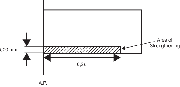
Figure 3.6.2 Extent of
strengthening of the aft end against bottom and bilge
slamming
- Where strengthening of the aft end is required, this is to
extend aft of 0,3L from the A.P. over the flat of bottom, bilge and
adjacent plating with attached stiffeners up to a height of 500 mm above the
baseline, see Figure 3.6.2 Extent of
strengthening of the aft end against bottom and bilge
slamming.
- Outside the region strengthened to resist bottom and bilge
slamming, the scantlings are to be tapered to maintain continuity of
longitudinal and/or transverse strength.
6.4.3
Design to resist bottom slamming loads.
- The design of end connections of stiffeners
in the bottom slamming region is to ensure end fixity, either by making the
stiffeners continuous through supports or by providing end brackets. Where
it is not practical to comply with this requirement, the net plastic section
modulus, Zpl-alt-net
, for alternative end fixity arrangements is not to be less than:
|
Zpl-alt-net
|
= |
 cm3 cm3
|
where
|
fbdg
|
= |
bending moment factor |
| = |

|
|
ns
|
= |
0 for both ends with low end fixity (simply
supported) |
| = |
1 for one end equivalent to built in and one end
simply supported. |
- Scantlings and arrangements at primary support members,
including bulkheads, are to comply with Pt 10, Ch 3, 6.4 Bottom and bilge slamming 6.4.7.
6.4.4
Hull envelope plating.
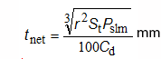
- The net thickness of the hull envelope plating,
tnet
, is not to be less than:
|
tnet
|
= |
 mm mm |
where
|
αp
|
= |
correction factor for the panel aspect ratio |
| = |
 but not to be taken as greater than 1,0 but not to be taken as greater than 1,0 |
|
lp
|
= |
length of plate panel, to be taken as the spacing
between primary support members or panel breakers, in
metres |
|
Cd
|
= |
plate capacity correction coefficient |
| = |
1,3 |
|
Ca
|
= |
permissible bending stress coefficient |
| = |
1,0 for acceptance criteria set AC3. |
6.4.5
Hull envelope stiffeners.
- The net plastic section modulus,
Zpl-net
, of each individual stiffener, is not to be less than:
|
Zpl-net
|
= |
 cm3 cm3
|
where
|
lbdg
|
= |
effective bending span, in metres |
|
fbdg
|
= |
bending moment factor |
| = |

|
|
Cs
|
= |
permissible bending stress coefficient |
| = |
0,9 for acceptance criteria set AC3. |
- The net web thickness, tw-net
, of each longitudinal is not to be less than:
|
tw-net
|
= |
 mm mm |
where
|
lshr
|
= |
effective shear span, in metres |
|
dshr
|
= |
effective web depth of stiffener, in mm |
|
Ct
|
= |
permissible shear stress coefficient |
| = |
1,0 for acceptance criteria set AC3. |
6.4.7
Primary support members.
- The size and number of openings in web
plating of the floors and girders are to be minimised, considering the
required shear area as given in Pt 10, Ch 3, 6.4 Bottom and bilge slamming 6.4.7.(b).
- The net shear area, Ashr-net50
, of each primary support member web at any position along its span is
not to be less than:
|
Ashr-net50
|
= |
 cm2 cm2
|
where
|
Ct
|
= |
permissible shear stress coefficient |
| = |
0,9 for acceptance criteria set AC3. |
- For simple arrangements of primary support
members, where the grillage effect may be ignored, the shear force,
Qslm
, is given by:
where
|
fpt
|
= |
correction factor for the proportion of patch load
acting on a single primary support member |
| = |
0,5 (fslm
3 – 2fslm
2 + 2) |
|
fslm
|
= |
patch load modification factor |
| = |
 , but not to be greater than 1,0 , but not to be greater than 1,0 |
|
lslm
|
= |
extent of slamming load area along the span |
| = |
 m, but not to be greater than
lshr m, but not to be greater than
lshr
|
|
lshr
|
= |
effective shear span, in metres |
|
bslm
|
= |
breadth of impact area supported by primary support
member |
| = |
 m, but not to be greater than S m, but not to be greater than S
|
|
S
|
= |
primary support member spacing, in metres. |

Figure 3.6.3 Distribution of
fdist along the span of simple primary support members
- For complex arrangements of primary support
members, the greatest shear force, Qslm
, at any location along the span of each primary support member is to be
derived by direct calculation in accordance with Table 3.6.1 Direct calculation
methods for derivation of Qslm.
Table 3.6.1 Direct calculation
methods for derivation of Qslm
| Type of
analysis
|
Beam
theory
|
Double bottom
grillage
|
| Model extent
|
Overall span of member between
effective bending supports
|
Longitudinal extent to be one cargo tank
length
Transverse extent to be between inner
hopper knuckle and centreline
|
| Assumed end fixity of
floors
|
Fixed at ends
|
Floors and girders to be
fixed at boundaries of the model
|
| NOTE
The envelope of
greatest shear force along each primary support
member is to be derived by applying the load patch
to a number of locations along the span, see
Pt 10, Ch 3, 6.4 Bottom and bilge slamming 6.4.7.(b).
|
- The net web thickness, tw-net
, of primary support members adjacent to the shell is not to be less
than:
|
tw-net
|
= |
 mm mm |
where
|
sw
|
= |
plate breadth, in mm, taken as the spacing between
the web stiffening. |
6.4.9 Bilge plating.
-
The thickness of bilge plating is not to be less than that
required for the adjacent bottom shell, see
Pt 10, Ch 3, 6.4 Bottom and bilge slamming 6.4.4.
- The net thickness of bilge plating,
tnet, without longitudinal stiffening is not to be
less than:
Where the plate seam is located in the flat plate just below the lowest stiffener on
the side shell, any increased thickness required for the bilge plating does not have
to extend to the adjacent plate above the bilge, provided that the plate seam is not
more than Sb/4 below the lowest side longitudinal. Similarly, for
flat part of adjacent bottom plating, any increased thickness for the bilge plating
does not have to be applied, provided that the plate seam is not more than
Sa/4 beyond the outboard bottom longitudinal. Regularly
longitudinally-stiffened bilge plating is to be assessed as a stiffened plate. The
bilge keel is not considered as ‘longitudinal stiffening’ for the application of
this requirement.
6.5 Bow impact
6.5.1
Application.
- The side structure in the area forward of 0,1L from the
FP is to be strengthened against bow impact pressures.
- The section modulus and web thickness of the local support
members apply to the areas clear of the end brackets. The section modulus of
the primary support member is to apply along the bending span clear of end
brackets and cross-sectional areas of the primary support member are to be
applied at the ends/supports and may be gradually reduced along the span and
clear of the ends/supports following the distribution of fdist
indicated in Figure 3.6.3 Distribution of
fdist along the span of simple primary support members.
6.5.3
Design to resist bow impact loads.
- In the bow impact region, longitudinal framing is to be carried
as far forward as practicable.
- The design of end connections of stiffeners in the bow impact
region are to ensure end fixity, either by making the stiffeners continuous
through supports or by providing end brackets. Where it is not practical to
comply with this requirement, the net plastic section modulus,
Zpl-alt-net
, for alternative end fixity arrangements is not to be less than:
|
Zpl-alt-net
|
= |
 cm3 cm3
|
where
|
fbdg
|
= |
bending moment factor |
| = |

|
|
ns
|
= |
0 for both ends with low end fixity (simply
supported) |
| = |
1,0 for one end equivalent to built-in and one end
simply supported. |
- Scantlings and arrangements at primary support members,
including decks and bulkheads, are to comply with Pt 10, Ch 3, 6.5 Bow impact 6.5.7. In areas of greatest bow impact load,
the adoption of web stiffeners arranged perpendicular to the hull envelope
plating and the provision of double sided lug connections are, in general,
to be applied.
- The main stiffening direction of decks and bulkheads supporting
shell framing is to be arranged parallel to the span direction of the
supported shell frames, to protect against buckling.
6.5.4
Side shell plating.
- The net thickness of the side shell plating, tnet
, is not to be less than:
|
tnet
|
= |

|
where
|
αp
|
= |
correction factor for the panel aspect ratio |
| = |
 but is not to be taken as greater than 1,0 but is not to be taken as greater than 1,0 |
|
lp
|
= |
length of plate panel, to be taken as the spacing
between the primary support members, or panel breakers, in
metres |
|
Ca
|
= |
permissible bending stress coefficient |
| = |
1,0 for acceptance criteria set AC3. |
6.5.5
Side shell stiffeners.
- The effective net plastic section modulus,
Zpl-net
, of each stiffener, in association with the effective plating to which
it is attached, is not to be less than:
|
Zpl-net
|
= |
 cm3 cm3
|
where
|
llbdg
|
= |
effective bending span, in metres |
|
fbdg
|
= |
bending moment factor |
| = |

|
|
Cs
|
= |
permissible bending stress coefficient |
| = |
0,9 for acceptance criteria set AC3. |
- The net web thickness, tw-net
, of each stiffener is not to be less than:
|
tw-net
|
= |
 mm mm |
where
|
lshr
|
= |
effective shear span, in metres |
|
dshr
|
= |
effective web depth of stiffener, in mm |
| = |
permissible shear stress coefficient |
| = |
1,0 for acceptance criteria set AC3. |
- The minimum net thickness of breasthooks/ diaphragm plates,
tw-net
, is not to be less than:
|
tw-net
|
= |
 mm mm |
where
|
s
|
= |
spacing of stiffeners on the web, in mm. Where no
stiffeners are fitted, s is to be taken as the depth of
the web. |
6.5.6
Definition of idealised bow impact load area for primary support members.
- The scantlings of items in Pt 10, Ch 3, 6.5 Bow impact 6.5.7 are based on the application of the
bow impact pressure to an idealised area of hull envelope plating, where the
bow impact load area, Aslm
, is given by:
|
Aslm
|
= |
 m2 m2
|
6.5.7
Primary support members.
- Primary support members in the bow impact region are to be
configured to ensure effective continuity of strength and the avoidance of
hard spots.
- To limit the deflections under extreme bow impact loads and
ensure boundary constraint for plate panels, the spacing, S, measured
along the shell girth of web frames supporting longitudinal framing or
stringers supporting transverse framing is not to be greater than:
- End brackets of primary support members are to be suitably
stiffened along their edge. Consideration is to be given to the design of
bracket toes to minimise abrupt changes of cross-section.
- Tripping brackets are to be fitted where the primary support
member flange is knuckled or curved. The torsional buckling mode of primary
support members is to be controlled by flange supports or tripping brackets.
The un - supported length of the flange of the primary support member, i.e.
the distance between tripping brackets, sbkt
, is not to be greater than:
|
sbkt
|
= |
 m, but need not be less than
sbkt-min m, but need not be less than
sbkt-min
|
where
|
bf
|
= |
breadth of flange, in mm |
|
C
|
= |
slenderness coefficient: |
| = |
0,022 for symmetrical flanges |
| = |
0,033 for one-sided flanges |
|
Af-net50
|
= |
net cross-sectional area of flange, in
cm2
|
|
Aw-net50
|
= |
net cross-sectional area of the web plate, in
cm2
|
- The net section modulus of each primary support member,
Znet50
, is not to be less than:
|
Znet50
|
= |
 cm3 cm3
|
where
|
fbdg-pt
|
= |
correction factor for the bending moment at the
ends and considering the patch load |
| = |
3fslm
3 – 8fslm
2 + 6fslm
|
|
fslm
|
= |
patch load modification factor |
| = |

|
|
lslm
|
= |
extent of bow impact load area along the span |
| = |
 m, but not to be taken as greater than
lbdg m, but not to be taken as greater than
lbdg
|
|
lbdg
|
= |
effective bending span, in metres |
|
bslm
|
= |
breadth of impact load area supported by the
primary support member, to be taken as the spacing between
primary support members, but not to be taken as greater than
lslm
, in metres |
|
fbdg
|
= |
bending moment factor |
| = |
12 for primary support members with end fixed
continuous face-plates, stiffeners or where stiffeners are
bracketed at both ends |
|
Cs
|
= |
permissible bending stress coefficient |
| = |
0,8 for acceptance criteria set AC3. |
- The net shear area of the web, Ashr-net50
, of each primary support member at the support/toe of end brackets is
not to be less than:
|
Ashr-net50
|
= |
 cm2 cm2
|
where
|
fpt
|
= |
patch load modification factor |
| = |

|
|
lslm
|
= |
extent of bow impact load area along the span |
| = |
 m, m,
but not to be taken as
greater than lshr
|
|
lshr
|
= |
effective shear span, in metres |
|
bslm
|
= |
breadth of impact load area supported by the primary
support member, to be taken as the spacing between primary
support members, but not greater than lslm
, in metres |
|
Ct
|
= |
permissible shear stress coefficient |
| = |
0,75 for acceptance criteria set AC3. |
- The net web thickness of each primary support member,
tw-net
, including decks/bulkheads in way of the side shell, is not to be less
than:
|
tw-net
|
= |
 mm mm |
where
|
bslm
|
= |
breadth of impact load area supported by the
primary support member, to be taken as the spacing between
primary support members, but not greater than lslm
, in metres |
|
ϕw
|
= |
angle, in degrees, between the primary support
member web and the shell plate |
|
σcrb
|
= |
critical buckling stress in compression of the web
of the primary support member or deck/bulkhead panel in way of
the applied load, in N/mm2. |
|