
Section
4 Shell envelope plating
4.1 Bottom and side shell
4.1.1 For
ferries and passenger ships classed 100A1 with a specified
operating area service notation the keel thickness for 0,4L amidships
is to be as required by Pt 4, Ch 1, 5 Shell envelope plating.
At ends, the keel thickness may be reduced by 25 per cent from the
above value, but is to be not less than that of the adjacent shell
plating.
4.1.2 The
thickness of side shell plating above 1,6T including
superstructures may require special consideration depending on the
particular structural arrangement, hull vertical bending and shear
stresses and position of the shell above the waterline. In no case
are the shell scantlings above 1,6T to be less than the
following:
-

-

-
as required by Pt 3, Ch 8 Superstructures, Deckhouses and Bulwarks
4.1.3 Openings
in the side shell and superstructure plating for windows and doors
are to be suitably stiffened and the thickness and grade of plating
in way will be specially considered.
4.1.6 The
minimum thickness of the shell plating at ends and for taper is to
be not less than the values given in Table 2.4.1 End shell thickness, and is in no case to be less than 6 mm.
4.1.7 For
ferries and passenger ships classed 100A1 with a specified
operating area service notation, the bottom and side shell minimum
thickness at ends may be taken 20 per cent less than that required
by Table 2.4.1 End shell thickness and Pt 3, Ch 5 Fore End Structure and Pt 3, Ch 6 Aft End Structure, but is in no case to be less than 6 mm.
Table 2.4.1 End shell thickness
| Scantling
length
|
Thickness, in
mm
|
| 70 m and below
|
(6,5 + 0,033L)  - 1,0 - 1,0
|
| Between 70 m and 110
m
|
(6,5 + 0,033L)  - 0,5 - 0,5
|
| Over 110 m
|
Pt 3, Ch 5 Fore End Structure and Pt 3, Ch 6 Aft End Structure
|
| Symbols
|
|
L as defined in Pt 3, Ch 1, 1.5 Intact stability
|
|
s
1, s
b as defined in Table 5.3.1 Shell and deck plating in Pt 3, Ch 5 Fore End Structure for fore end or Table 6.3.1 Shell plating aft in Pt 3, Ch 6 Aft End Structure for aft end
|
4.2 Bow flare and wave impact pressures
4.2.1 This
Section is applicable to:
-
bow flare region;
-
sides and undersides
of sponsons; and
-
other parts of
the side shell plating close to and above the design waterline that
are expected to be subjected to wave impact pressures.
The wave impact pressure, P
bf , in kN/m2 due to relative motion is to be taken as:
|
|
= |

|
where
|
K
bf
|
= |
hull form shape coefficient for wave impacts |
| = |
 for ψ ≥ 10 for ψ ≥ 10
|
| = |
28 (1 - tan (2ψ)) for ψ < 10 |
|
V
bf
|
= |
wave impact velocity, in m/s, and is given by |
| = |
 for N
bf ≥ 1 for N
bf ≥ 1 |
| = |
0 for N
bf < 1
|
|
V
thbf
|
= |
threshold velocity for wave impact, in m/s, to be taken as: |
| = |

|
|
|
= |
In ( ) is the natural logarithm |
|
N
bf
|
= |
No. of wave impacts in a three hour period and is given by |
| = |
1720 PR
bf

|
|
PR
bf
|
= |
probability of a wave impact and is given by |
| = |
e-u
|
| = |

|
|
Z
wl
|
= |
distance of the centroid of the area of plating or stiffener
above the local design waterline |
|
m
1
|
= |
variance of the relative vertical velocity |
| = |
0,25(ωe
f
sl
H
rm)2
|
|
m
0
|
= |
variance of the relative vertical motion |
| = |
0,25 (f
sl
H
rm)2
|
|
ωe
|
= |
effective
encounter wave frequency |
| = |

|
|
|
= |
where |
|
q
|
= |
1,0
for  ≥ 0,5 ≥ 0,5
|
|
|
= |
–0,6 for  < 0,5 < 0,5
|
|
ω |
= |
effective
wave frequency based on 80 per cent ship length |
| = |

|
|
f
sl
|
= |
probability level correction factor for relative vertical motion |
| = |
1,0 for C
b ≤ 0,6
|
| = |
1,2 for C
b > 0,6
|
|
V
sl
|
= |
0,515V, in m/s
|
|
K
rv
|
= |
hull form shape coefficient for impact due to forward speed |
| = |
 for αp ≤ 80 for αp ≤ 80
|
| = |
28 (1 – tan (2 (90 – αp)))
for αp > 80
|
|
H
rv
|
= |
relative wave heading coefficient |
| = |
for  ≥ 0,5 ≥ 0,5
|
| = |
1 for γp > 45
|
| = |
cos(45 – γp) for γp ≤ 45
|
| = |
for  < 0,5 < 0,5
|
| = |
0 |
|
|
= |
The point at which the following angles are to be measured for
assessment of plating and stiffeners is detailed in Table 2.4.2 Positions at which αp,
βp and γp are to be measured :
|
|
V
rv
|
= |
relative forward speed, in m/s |
| = |
0,515V sin γp
|
|
αp
|
= |
buttock
angle measured in the longitudinal plane, in degrees, see
Figure 2.4.1 Bow flare and bottom slamming angles and Table 2.4.2 Positions at which αp,
βp and γp are to be measured
|
|
ψ |
= |
effective
deadrise angle, in degrees
For C
b >
0,6, ψ is to be taken as the maximum of αp and
βp, see
Figure 2.4.1 Bow flare and bottom slamming angles and Table 2.4.2 Positions at which αp,
βp and γp are to be measured
For C
b ≤ 0,6, ψ is to be
taken as the maximum of αp and β
|
|
|
= |
where |
|
β |
= |
βp –
10°, but is to be taken as not less than 0°
|
|
|
= |
NOTE |
|
|
= |
The 10° deduction is to allow for the effects of roll motion
on the impact pressures. |
|
γp
|
= |
waterline
angle measured in the horizontal plane, in degrees, see
Figure 2.4.1 Bow flare and bottom slamming angles and Table 2.4.2 Positions at which αp,
βp and γp are to be measured .
|
|
|
= |
NOTE |
|
|
= |
Where only two angles are known and are measured in orthogonal
planes, the third angle may be obtained by the following expression: |
|
αp
|
= |
tan–1 (tan βp tan γp)
|
The relative vertical motion, H
rm, is
to be taken as

where
|
C
w,min
|
= |

|
|
C
w
|
= |
a wave head in metres |
| = |
0,0771L
WL (C
b + 0,2)0,3
e
(–0,0044LWL)
|
|
k
m
|
= |

|
|
x
m
|
= |
0,45 – 0,6F
n but is not to be
less than 0,2
|
|
F
n
|
= |

|
|
L
WL
|
= |
waterline length at summer load draught |
|
X
WL
|
= |
longitudinal distance, in metres, measured forwards from the
aft end of the L
WL to the location being considered
|
|
V
|
= |
speed,
in knots |
| = |
for  ≥ 0,5 ≥ 0,5
|
|
|
= |
is to be taken
as the maximum service speed, in knots, as defined in Pt 3, Ch 1, 6 Definitions For passenger yachts not
required to maintain high speeds in severe weather, the value of V may
be specially considered, but is not to be taken as less than the greater
of  or 5 knots. Where V has been specially considered
it is to be noted in the classification records as a memorandum that
should state: “A design speed of … knots has been used
for the assessment of bow structure with regards to bow flare impacts.
It should be noted that this speed may not be appropriate for all
conditions and it is the responsibility of the Master to apply good
Seamanship to minimise bow flare slamming.” or 5 knots. Where V has been specially considered
it is to be noted in the classification records as a memorandum that
should state: “A design speed of … knots has been used
for the assessment of bow structure with regards to bow flare impacts.
It should be noted that this speed may not be appropriate for all
conditions and it is the responsibility of the Master to apply good
Seamanship to minimise bow flare slamming.”
|
| = |
for  < 0,5 < 0,5
|
| = |
0 knots, for passenger ships |
| = |
5 knots, for all other ship types |
|
C
b
|
= |
Rule block coefficient. |
Table 2.4.2 Positions at which αp,
βp and γp are to be measured
| Framing system
|
Plating
|
Secondary stiffeners
|
| Longitudinally framed
|
Mid-distance between
longitudinals
|
Mid-distance between frames
|
| Transversely framed
|
0,5s from the bottom edge of
the plate strake or primary member
|
Mid-distance between primary
members
|
4.2.2 Alternatively, P
bf may be derived by the direct calculations carried
out in accordance with a procedure agreed by LR.
4.3 Strengthening for wave impact loads
4.3.1 The
shell envelope in the forward and after portions of the hull are to
be strengthened against bow flare or wave impact pressure. Typically,
strengthening is to be considered over the following areas:
- over the after body in way of a flat counter stern which is close
to the waterline;
- over the fore end side and bow structure above the waterline and
up to the deck at side;
- other areas where the hull exhibits significant flare.
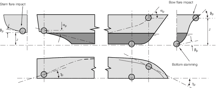
Figure 2.4.1 Bow flare and bottom slamming angles
4.3.2 The
thickness of the side shell plating is to be not less than:
4.3.3 The
structural scantlings required in areas strengthened against bow flare
slamming are to be tapered to meet the normal shell envelope requirements.
|