
Section
5 Shell envelope framing
5.1 Side structure
5.1.1 The
scantlings of frames, or side longitudinals, web frames or transverses,
and stringers below 1,6T above base are to satisfy the
requirement of Pt 4, Ch 1 General Cargo Ships and this
Section, but may be required to be confirmed by direct calculation.
The scantlings of these members above 1,6T from base
may require special consideration on the basis of the particular structural
arrangements, design deck loading, hull vertical bending stresses,
and position of the member above the waterline.
5.1.2 The
scantlings of side transverses supporting shell longitudinals above
1,6T are to satisfy the requirements of:
-
Pt 4, Ch 1, 6 Shell envelope framing, Pt 3, Ch 5, 4 Shell envelope framing and Pt 3, Ch 6, 4 Shell envelope framing.
-
The minimum geometric
properties required in order to provide rotational constraint to the
end of the deck transverse in way:
but is not to be less than 0,339S k P
s
L
d
2 cm3
 s is not to be less than
  d
d
 cm4 cm4
where
|
P
s
|
= |
deck design loading, in kN/m2, see
Table 2.3.1 Design deck loadings (ferries and
passenger ships only)
|
|
L
d
|
= |
span of adjacent deck transverse, in metres |
|
Z
d
|
= |
actual modulus of adjacent deck transverse, in cm3
|
|
Z
dR
|
= |
Rule modulus of adjacent deck transverse, in cm3
|
 d
d
|
= |
moment of
inertia of adjacent deck transverse, in cm4
|
|
L
s
|
= |
span of side shell transverse, in metres |
 s
s
|
= |
moment of
inertia of side shell transverse, in cm4
|
|
S, k
|
= |
as defined in Pt 4, Ch 2, 1.5 Symbols 1.5.1
|
|
|
= |
Due account should be taken of the shell window dimensions when
determining the effective width of attached plating. |
5.1.3 The
required modulus of transverse main and 'tween deck frames, which
may have reasonably constant convex curvature over their entire length,
may be corrected for curvature as follows:
|
Z
min
|
= |
Z
rule
 cm3 cm3
|
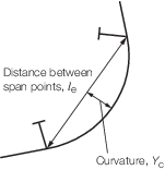
Figure 2.5.1 Distance between span support points and curvature
5.1.4 Where
ramp openings are fitted adjacent to the ship’s side, adequate
support for the side framing is to be provided.
5.2 Strengthening for wave impact loads
5.2.1 The
side structure in the forward and after portions of the hull is to
be strengthened against bow flare or wave impact pressure. Typically,
strengthening is to be considered over the following areas:
- over the after body in way of a flat counter stern which is close
to the waterline.
- over the fore end side and bow structure above the waterline and
up to the deck at side.
- other areas where the hull exhibits significant flare.
5.2.2 The
scantlings of secondary stiffeners are not to be less than:
-
Effective plastic
section modulus of stiffeners:
|
Z
p
|
= |
3,75h
s
s
cm
kl
e
2 x 10⁻³ cm3
|
Other symbols are as defined in Pt 4, Ch 2, 1.5 Symbols 1.5.2.
-
Web area of secondary
stiffeners
|
A
|
= |
3,7s
cm
k h
s
 x 10–4 cm2 x 10–4 cm2
|
where
Other symbols are as defined in Pt 4, Ch 2, 1.5 Symbols 1.5.2.
5.2.3 The
effective section properties of secondary stiffeners are to be taken
as:
-
Plastic section
modulus of secondary stiffeners, Z
p, is to
be taken as:
|
Zp
|
= |
(2,8 x 10⁻⁴ scm
tp2) - (10-3
bf
bfc
tf sinθe) +(5 x 10⁻⁴
(hw2
tw + 2bf
tf
hw) cosθe) cm3 |
where
|
θe
|
= |
C
0 (90 – φ)
|
|
Co
|
= |
1,1 |
|
φ |
= |
the angle
between the stiffener and the side shell, in degrees |
|
b-fc
|
= |
0,5 (b
f – t
w)
for L profiles
|
| = |
0 for flat bar and T profiles |
| = |
 for bulb profiles, see
Figure 4.7.1 Dimensions of longitudinals in Pt 3, Ch 4 Longitudinal Strength, for c for bulb profiles, see
Figure 4.7.1 Dimensions of longitudinals in Pt 3, Ch 4 Longitudinal Strength, for c |
|
h
w
|
= |
height of stiffener web, in mm |
|
t
w
|
= |
web thickness, in mm |
|
b
f
|
= |
breadth of flange, in mm |
|
t
f
|
= |
flange thickness, in mm |
|
t
p
|
= |
thickness of attached plating, in mm |
-
Web area of secondary stiffeners, A
s, is to be taken as:
|
A
s
|
= |
0,01 (h
w + t
p) t
w sinφ cm2
|
5.2.4 Where
the stiffener web is not perpendicular to the plating, tripping brackets
have to be fitted in order to obtain adequate lateral stability.
5.2.5 The
scantlings of primary members are not to be less than:
-
Section modulus
of primary members
|
Z
|
= |
2 γz
k h
s
q v
 e
2 cm3
e
2 cm3
|
-
Web area of primary
members
|
A
|
= |
0,2 γA
k h
s
q v
 e cm2
e cm2
|
γA and γZ are strength factors
dependent on the load position
for q <
1 γA = q
3 – 2q
2 + 2 and γZ = 3q
3 –
8q
2 + 6q
for q =
1 γA = 1 and γZ = 1
|
q
|
= |
 but ≤ 1 but ≤ 1
|
for web frames:
|
u
|
= |
is the minimum of g
bfv or  e
e
|
|
v
|
= |
is the minimum of g
bfh or S
cm
|
for primary stringers:
|
u
|
= |
is the minimum of g
bfh or  e
e
|
|
v
|
= |
is the minimum of g
bfv or S
cm
|
-
The web of the
primary member is to be adequately stiffened.
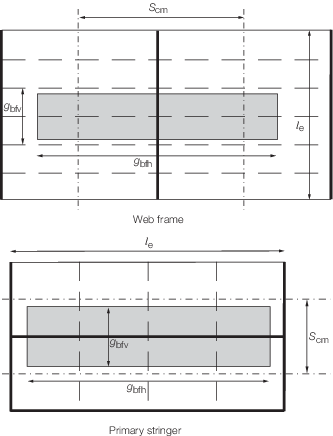
Figure 2.5.2 Mean spacing between primary members, S
cm,
and the extents of wave impact pressure g
bfh and g
bfv
5.2.6 The
extents of the wave impact pressure are to be derived as follows:
-
the vertical extent, g
bfv, is to be taken as:
-
the horizontal
extent, g
bfh, is to be taken as:
5.2.7 For
primary members with cut-outs for the passage of secondary stiffeners,
and which may have web stiffeners connected to the secondary stiffener,
buckling checks are to be carried out to ensure that the primary member
web plating and web stiffener will not buckle under the design load.
The buckling procedure to be followed is given in Table 5.1.3 Buckling procedure for primary
member web plating and web stiffener in Pt 3, Ch 5 Fore End Structure. Where the web stiffener is
fitted with a bracket, the buckling capability of the web stiffener
in way of the cut-out is to take account of the bracket. Where no
web stiffener is fitted, the buckling capability of the primary member
web plating is to be checked for the total load transmitted to the
connection.
5.2.8 Where
the angle between primary structure web and the plating is less than
70°, the effective section modulus and shear area are to take
account of the non-perpendicularity.
5.2.9 The
structural scantlings required in areas strengthened against bow flare
slamming are to be tapered to meet the normal shell envelope requirements.
|