
Section
6 Shell envelope framing
6.1 General
6.1.1 Longitudinal
framing is, in general, to be adopted at the bottom, but special consideration
will be given to proposals for transverse framing in this region.
Transverse or longitudinal framing can be adopted for the side shell.
Requirements are given in this Section for longitudinal and transverse
framing systems.
6.1.2 End
connections of longitudinals to bulkheads are to provide adequate
fixity and, so far as practicable, direct continuity of longitudinal
strength. Where L exceeds 215 m, the bottom longitudinals
are to be continuous in way of both watertight and non-watertight
floors, but alternative arrangements will be considered. Higher tensile
steel longitudinals within 10 per cent of the ship's depth at the
bottom and deck are to be continuous irrespective of the ship length, see also
Pt 3, Ch 10, 5.2 Arrangements at intersections of continuous secondary and primary members.
6.1.3 Stiffeners
and brackets on side transverses, where fitted on one side and connected
to higher tensile steel longitudinals between the base line and 0,8D
2 above the base line, are to have their heels
well radiused to reduce stress concentrations. Where a symmetrical
arrangement is fitted, i.e. bracket or stiffening on both sides, and
it is connected to higher tensile steel longitudinals, the toes of
the stiffeners or brackets are to be well radiused. Alternative arrangements
will be considered if supported by appropriate direct calculations, see also
Pt 3, Ch 10, 5.2 Arrangements at intersections of continuous secondary and primary members.
6.1.4 Where
higher tensile steel side longitudinals pass through transverse bulkheads
in the cargo area, well radiused brackets of the same material are
to be fitted on both the fore and aft side of the connection between
the upper turn of bilge and 0,8D
2 above the
base line. Particular attention should be given to ensuring the alignment
of these brackets. Alternative arrangements will be considered if
supported by appropriate direct calculations, see also
Pt 4, Ch 1, 6.2 Longitudinal stiffening 6.2.3.
6.2 Longitudinal stiffening
6.2.2 The
lateral and torsional stability of longitudinals together with web
and flange buckling criteria are to be verified in accordance with Pt 3, Ch 4, 7 Hull buckling strength.
6.2.3 Where
higher tensile steel asymmetrical sections are adopted in double bottom
tanks which are interconnected with double skin side tanks or combined
hopper and topside tanks the requirements of Pt 4, Ch 1, 6.1 General 6.1.3 and Pt 4, Ch 1, 6.1 General 6.1.4 are to be complied with regarding
arrangements to reduce stress concentrations. Alternatively, it is
recommended that bulb plate or symmetrical sections are adopted.
6.3 Transverse stiffening
6.3.1 The
scantlings of main and 'tween deck frames, and bottom frames in way
of bracket floors, in the midship region are to comply with the requirements
given in Table 1.6.3 Shell framing (transverse).
6.3.2 The
scantlings of main frames are normally to be based on Rule standard
brackets at top and bottom, whilst the scantlings of 'tween deck frames
are normally to be based on a Rule standard bracket at the top only.
6.4 Primary supporting structure
6.4.1 Side transverses supporting longitudinal stiffening, and webs and stringers supporting transverse side stiffening, are to
comply with the requirements of
Table 1.6.4 Primary structure.
6.4.2 Side transverses are to be spaced not more than 3,8 m apart when the length,
L, is less than 100 m and (0,006L + 3,2) m apart where
L is greater than 100 m.
Table 1.6.1 Shell framing (longitudinal)
| Location
|
Modulus, in cm3
|
| (1) Side longitudinals in way of dry spaces, including double skin construction,
see Note 2
|
The lesser of the following:
(a) 
(b)
Z from (3)(a) evaluated using
s,
k and
le for the longitudinal under consideration and the remaining parameters evaluated at the base line
|
| (2) Side longitudinals in way of double skin tanks or deep tanks,
see Note 2
|
The greater of the following:
(a)
Z as from (1)
(b) As required by
Ch1, 9 for deep tanks
|
| (3) Bottom and bilge longitudinals,
see Notes 1, 2, 3 and 4
|
The greater of the following:
(a) 
(b) 
|
| Symbols
|
|
L, D, T, s, k,kL, ρ, as defined in
Pt 4, Ch 1, 1.5 Symbols and definitions 1.5.1
le = as defined in Pt 4, Ch 1, 1.5 Symbols and definitions 1.5.1, but is not
to be taken less than 1,5 m except in way of the centre girder
brackets required by Pt 4, Ch 1, 8.5 Floors 8.5.3 where a
minimum span of 1,25 m may be used
le1 =
le in metres, but is not to be taken less than 2,5 m and need not be taken greater than 5,0 m
|
|
 at deck at deck
C1 = 1,0 at 
C1 =  at baseline at baseline
Intermediate values of c1 are to be obtained by
interpolation.
D1 =
D2, in metres, but is not to be taken less than 10 and need not be taken greater than 16
D2 = D, in metres, but need not be taken greater than
1,6T
FB,FD as defined in
Pt 3, Ch 4, 5.7 Local reduction factors
|
|
 for side longitudinals above for side longitudinals above 
F1=  for side longitudinals below for side longitudinals below and for bottom longitudinals and for bottom longitudinals
F1 is not to be taken less than =
0,14
|
|
L1 =
L but need not be taken greater than 190 m
Fs is a fatigue factor for side
longitudinals to be taken as follows:
- (a) For built sections and rolled angle bars
 at 0,6D2 above the base line at 0,6D2 above the base line
- FS = 1,0 at
D2 and above
- FS = FSB at the base
line.
Intermediate values of Fs are to be obtained
by interpolation.
|
- (b) For flat bars and bulb plates
 may be taken as 0,5 may be taken as 0,5
- Fsb is a fatigue factor for bottom longitudinals = 0,5 (1 +
Fs at 0,6D2)
|
|
Where
bf1 = the minimum distance, in mm, from the edge of the face
plate of the side longitudinal under consideration to the centre
of the web plate, see
Pt 4, Ch 9, 5.2 Symbols 5.2.1
 in metres, for longitudinals above the waterline, at
draught T in metres, for longitudinals above the waterline, at
draught T
Where Cw is not to be taken less than is not to be taken less than  m for Type ‘B-60’ ships or less than the greater of m for Type ‘B-60’ ships or less than the greater of
 or 1,20 for Type ‘B’ ships or 1,20 for Type ‘B’ ships
hT1 =  in metres, for longitudinals below the waterline at
draught T. in metres, for longitudinals below the waterline at
draught T.
|
|
hT1 need not exceed  and and 
hT2 = (T + 0,5CW), in metres for
bottom longitudinals but need not be taken greater than
1,2T
hT3 =
h4 - 0,25T, in metres
h4 = load head required by Pt 4, Ch 1, 9.1 General for deep tanks
h5 = vertical distance, in metres, from longitudinal to deck at depth,
D2
h6 = vertical distance, in metres, from the waterline at draught
T to the longitudinal under consideration
bf = the width of the face plate, in mm, of the side
longitudinal under consideration, see
Pt 4, Ch 9, 5.2 Symbols 5.2.1
CW = a wave head, in metres = 7,71 x 10⁻²Le-0,0044L where
e = base of natural logarithms 2,7183
Fλ = 1,0 for
L ≤ 200 m
= [1,0 + 0,0023(L – 200)] for
L > 200 m
γ = 0,002le1 + 0,046
|
|
NOTES
Note 1. The buckling requirements
of Pt 3, Ch 4, 7 Hull buckling strength are to be
complied with. The ratio of the web depth,
dw, to web thickness, t, is to
comply with the following requirements:
- (a) Built up profiles and rolled angles:

- (b) Flat bars:
 when continuous at bulkheads when continuous at bulkheads
 when non-continuous at bulkheads when non-continuous at bulkheads
Note 2. Where struts are fitted midway
between transverses in way of double bottom tanks, or double
skin construction, the modulus of the bottom or side
longitudinals may be reduced by 50k per cent from that
obtained from the locations (1), (2), or (3) as applicable.
Note 3. Where the bilge radius exceeds the Rule height of a double bottom the modulus of the longitudinal above this nominal height
is to be derived from the location (1) or (2) as applicable.
|
Table 1.6.2 Shell framing (longitudinal)
| Location
|
Modulus, in cm3
|
| (1) Side longitudinals in way of dry spaces, including double skin construction,
see Note 2
|
The lesser of the following:
(a) 
(b)
Z from (3)(a) evaluated using
s and
le for the longitudinal under consideration and the remaining parameters evaluated at the base line
|
| (2) Side longitudinals in way of double skin tanks or deep tanks,
see Note 2
|
The greater of the following:
(a)
Z as from (1)
As required by
Pt 4, Ch 1, 9.1 General for deep tanks using
hT3 instead of
h4, but need not exceed
Z from (3)(b) evaluated using γ, s and fige for the longitudinal under consideration and the remaining parameters evaluated
at the base line
|
| (3) Bottom and bilge longitudinals,
see Notes 1, 2, 3 and 4
|
The greater of the following:
(a) 
(b) 
|
| Symbols
|
|
L, D, T, s, k, ρ, as defined in
Pt 4, Ch 1, 1.5 Symbols and definitions 1.5.1
le = as defined in Pt 4, Ch 1, 1.5 Symbols and definitions 1.5.1, but is not
to be taken less than 1,5 m except in way of the centre girder
brackets required by Pt 4, Ch 1, 8.5 Floors 8.5.3 where a
minimum span of 1,25 m may be used
le1 =
le in metres, but is not to be taken less than 2,5 m and need not be taken greater than 5,0 m
|
|
 at deck at deck
c1 = 1,0 at 
c1 =  at baseline at baseline
intermediate values c1 are to be obtained by interpolation
D1 =
D2, in metres, but is not to be taken less than 10 and need not be taken greater than 16
D2 = D, in metres, but need not be taken greater than
1,6T
FB,FD as defined in
Pt 3, Ch 4, 5.7 Local reduction factors
|
|
 for side longitudinals above for side longitudinals above 
F1 =  for side longitudinals below for side longitudinals below  and bottom longitudinals and bottom longitudinals
F1 is not to to be taken less than
0,14
|
|
L1 =
L but need not be taken greater than 190 m
Fs is a fatigue factor for side
longitudinals to be taken as follows:
- (a) For built sections and rolled angle bars
 at 0,6D2 above the base line at 0,6D2 above the base line
- FS = 1,0 at
D2 and above,
- FS = FSB at
the base line
Intermediate values of Fs are to be obtained
by linear interpolation.
|
- (b) For flat bars and bulb plates
 may be taken as 0,5 may be taken as 0,5
- Fsb is a fatigue factor for bottom longitudinals = 0,5 (1 +
Fs at 0,6D2)
|
|
Where
bf1 = the minimum distance, in mm, from the edge of the face
plate of the side longitudinal under consideration to the centre
of the web plate, see
Pt 4, Ch 9, 5.2 Symbols 5.2.1
 in metres, for longitudinals above the waterline, at
draught T in metres, for longitudinals above the waterline, at
draught T
Where  is not to be taken less than 0,7 is not to be taken less than 0,7
hT1 =  in metres, for longitudinals below the waterline at
draught T. in metres, for longitudinals below the waterline at
draught T.
|
|
hT1 and hT2 need not exceed  and and 
hT2 = (T + 0,5CW)
Fλ, in metres for bottom longitudinals
hT3 = h4 - 0,25T, in
metres at the base line
hT3 = h4 in metres, at and
above T/4 from the base line
Intermediate values of hT
3 are to be obtained by linear interpolation
h4 = load head required by Pt 4, Ch 1, 9.1 General for deep tanks
h5 = vertical distance, in metres, from longitudinal to deck at depth,
D2
h6 = vertical distance, in metres, from the waterline at draught
T to the longitudinal under consideration
bf = the width of the face plate, in mm, of the side
longitudinal under consideration, see
Pt 4, Ch 9, 5.2 Symbols 5.2.1
CW = a wave head, in metres = 7,71 x 10⁻²Le-0,0044L where
e = base of natural logarithms 2,7183
Fλ = 1,0 for
L ≤ 200 m
= [1,0 + 0,0023(L – 200)] for
L > 200 m
γ = 0,002le1 + 0,046
|
|
NOTES
Note 1. The buckling requirements
of Pt 3, Ch 4, 7 Hull buckling strength are to be
complied with. The ratio of the web depth,
dw, to web thickness, t, is to
comply with the following requirements:
- (a) Built up profiles and rolled angles:

- (b) Flat bars:
 when continuous at bulkheads when continuous at bulkheads
 when non-continuous at bulkheads when non-continuous at bulkheads
Note 2. Where struts are fitted midway
between transverses in way of double bottom tanks, or double
skin construction, the modulus of the bottom or side
longitudinals may be reduced by 50k per cent from that
obtained from the locations (1), (2), or (3) as applicable.
Note 3. Where the bilge radius exceeds the Rule height of a double bottom the modulus of the longitudinal above this nominal height
is to be derived from the location (1) or (2) as applicable.
|
Table 1.6.3 Shell framing (transverse)
| Location
|
Modulus, in cm3
|
Inertia, in cm4
|
| (1)Main, 'tween deck and superstructure frames in dry spaces,
see Note 3
|
The greater of the following: (a)
Z = C s k h
T1
H
2 x 10⁻³
|
|
| (b)
Z = 9,1skD
1 x 10⁻³
|
| (2)Main and 'tween deck frames in way of fuel or water ballast tanks or cargo holds used for water ballast
|
The greater of the following:
(a)1,15 x
Z from (1)
|
|
|
(b)Z = 6,7s k h H
2
2 x 10⁻³
|
| (3)Frames supporting hatch end beams or deck transverses,
see Note 2
|
The greater of the following:
(a)Z from (1)
|
|
|
(b)Z = 2,5 (0,2l
s
2 +
H
1
2)k S
1
H
g
|
| (4)Bottom frames of double bottom bracket floors
|
|
—
|
| Symbols
|
|
D, T, s, k as defined in
Pt 4, Ch 1, 1.5 Symbols and definitions 1.5.1
|
|
C
|
= |
end connection factor
|
| = |
3,4 where two Rule standard brackets are fitted
|
| = |
3,4 (1,8 - 0,8 ( a/
a/ ) where one Rule standard bracket and one reduced bracket fitted ) where one Rule standard bracket and one reduced bracket fitted
|
| = |
3,4 (2,15 - 1,15 ( amean/
 ) where two reduced brackets are fitted ) where two reduced brackets are fitted
|
| = |
6,1 where one Rule standard bracket is fitted
|
| = |
6,1 (1,2 - 0,2 ( a/
a/ ) where one reduced bracket is fitted ) where one reduced bracket is fitted
|
| = |
7,3 where no bracket is fitted
|
|
| The requirements for frames where brackets larger than Rule standard are fitted will be specially considered
|
|
|
|
l
amean
|
= |
mean equivalent arm length, in mm, for both brackets
|
|
|
h
T1
|
= |
head, in metres, at middle of
H
|
| = |
C
w  , in metres for frames where the mid-length of frame is above the waterline, at draught
T , in metres for frames where the mid-length of frame is above the waterline, at draught
T
where is not to be taken less than 0,7 is not to be taken less than 0,7
|
| = |
[h
6 +
C
w  ]F
λ, in metres for frames where the mid-length of frame is below the waterline at draught
T ]F
λ, in metres for frames where the mid-length of frame is below the waterline at draught
T
|
|
|
h
|
= |
h
4 or
h
5, whichever is the greater
|
|
|
|
|
h
5
|
= |
head, in metres, measured from the mid-length of
H, to the deck at side
|
|
|
h
6
|
= |
vertical distance in metres, from waterline at draught
T to the mid-length of
H
|
|
|
l
s
|
= |
distance, in metres, from side shell to inboard support of beam or transverse
|
|
|
l
e
|
= |
effective length, in metres, of bottom frames for double bottom bracket floors
|
|
|
l
h
|
= |
length, in metres, of hatch side girder
|
|
|
C
w
|
= |
a wave head, in metres,
|
| = |
7,71 x 10⁻²
Le
-0.0044L
|
| = |
where e = base of natural logarithm 2,7183
|
|
|
Fλ
|
= |
1,0 for
L ≤ 200 m
|
| = |
(1,0 + 0,0023 (L - 200)) for
L > 200 m
|
|
|
D
1
|
= |
D, but need not be taken greater than 1,6T
|
|
|
H
|
= |
H
MF or
H
TF as applicable,
see Note 1
|
|
|
|
|
|
|
H
1
|
= |
H, but need not be taken greater than 3,5 m
|
|
|
H
2
|
= |
H, where
H
MF is to be taken not less than 2,5 m
|
|
|
|
|
S
|
= |
spacing, in metres, of deck transverses
|
|
|
S
1
|
= |
 for hatch end beams for hatch end beams
|
| = |
S for transverses
|
|
Note
1.
Where frames are inclined at more than 15° to the vertical,
H
MF or
H
TF is to be measured along a chord between span points of the frame.
Note
2.
If the modulus obtained from (3) for frames under deck transverses exceeds that obtained from (1) and (2), the intermediate
frames may be reduced provided that the combined modulus is maintained and the reduction in any intermediate frame is not
greater than 35 per cent. The reduced modulus is to be not less than that given by (1)(b).
Note
3.
The scantlings of main frames are not to be less than those of the 'tween deck frames above.
|
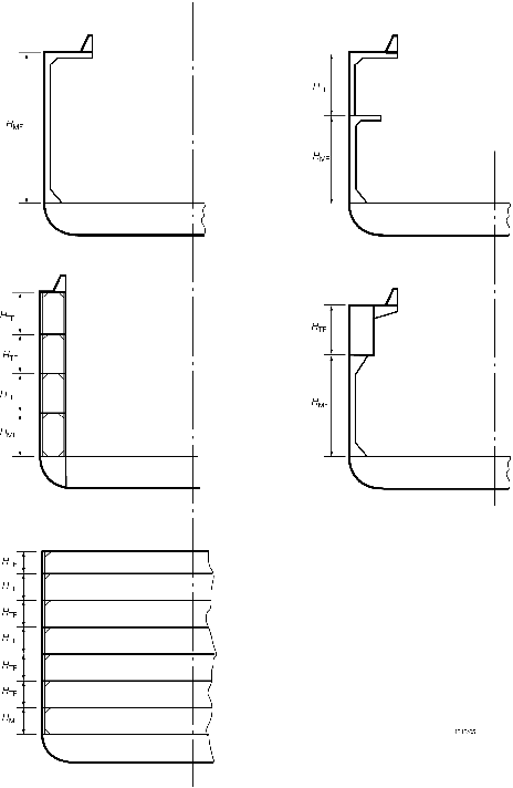
Figure 1.6.1 Framing depths for various structural configurations
Table 1.6.4 Primary structure
| Item and location
|
Modulus, in cm3
|
Inertia, in cm4
|
| Longitudinal framing system:
|
|
|
| (1)Side transverses in dry cargo spaces
|
Z = 10k S h
T1
l
e
2
|
—
|
| (2)Side transverses in deep tanks
|
Z = 11,7ρ k S h
4
l
e
2
or as (1) above, whichever is the greater
|
|
| Transverse framing system:
|
|
|
| (3)Side stringers in dry cargo spaces
|
Z = 7,75
k S h
T1
l
e
2
|
—
|
| (4)Side stringers in deep tanks
|
Z = 11,7ρ k S h
4
l
e
2
or as (3) above, whichever is the greater
|
|
| (5)Web frames supporting side stringers
|
Z determined from calculation based on following assumptions:
|
|
| (a)fixed ends
|
| (b) point loadings
|
| (c)head
h
4 or
h
T1 as applicable
|
(d) bending stress
|
(e) shear stress
|
| Symbols
|
|
h
T1
|
= |
head, in metres, at mid-length of span
|
| = |
C
w  F
λ, in metres where mid-length of span is above the waterline at draught
T, where
F
λ, in metres where mid-length of span is above the waterline at draught
T, where
 is not to be taken less than 0,7 is not to be taken less than 0,7
|
| = |
 F
λ, in metres where mid-length of span is below the waterline at draught
T
F
λ, in metres where mid-length of span is below the waterline at draught
T
|
|
where
|
h
6
|
= |
vertical distance, in metres, from the waterline at draught
T, to the mid-length of span
|
|
F
λ
|
= |
1,0 for
L ≤ 200 m
|
| = |
[1,0 + 0,0023 (L
– 200)] for
L > 200 m
|
|
C
w
|
= |
a wave head, in metres
|
| = |
7,71 × 10⁻²
L
e
–0,0044L
where e = base of natural logarithms 2,7183
|
|
D
1
|
= |
D
but need not be taken greater than 1,6T
|
|
|