
Section
3 Secondary member end connections
3.1 General
3.1.1 Secondary
members, that is longitudinals, beams, frames and bulkhead stiffeners
forming part of the hull structure, are generally to be connected
at their ends in accordance with the requirements of this Section.
Where it is desired to adopt bracketless connections, the proposed
arrangements will be individually considered.
3.1.2 Where
end connections are fitted in accordance with these requirements,
they may be taken into account in determining the effective span of
the member.
3.2 Symbols
3.2.1 The
symbols used in this Section are defined as follows:
|
a, b
|
= |
the
actual lengths of the two arms of the bracket, in mm, measured from
the plating to the toe of the bracket |
|
b
f
|
= |
the breadth of the flange, in mm |
|
t
|
= |
the
thickness of the bracket, in mm |
|
Z
|
= |
the
section modulus of the secondary member, in cm3.
|
3.3 Basis for calculation
3.3.1 Where
a longitudinal strength member is cut at a primary support and the
continuity of strength is provided by brackets, the scantlings of
the brackets are to be such that their section modulus and effective
cross-sectional area are not less than those of the member. Care is
to be taken to ensure correct alignment of the brackets on each side
of the primary member.
3.3.2 In
other cases the scantlings of the bracket are to be based on the modulus
as follows:
-
Bracket connecting
stiffener to primary member:
modulus of the stiffener.
-
Bracket at the
head of a main transverse frame where frame terminates:
modulus
of the frame.
-
Brackets connecting
lower deck beams or longitudinals to the main frame in the forward
0,15L:
modulus of the frame.
-
Elsewhere: the
lesser modulus of the members being connected by the bracket.
3.4 Scantlings of end brackets
3.4.1 The
lengths, a and b, of the arms are to be
measured from the plating to the toe of the bracket and are to be
such that:
-
a + b ≥ 2,0
-
a ≥
0,8
-
b ≥
0,8
where
but in no case is l to be taken as less
than twice the web depth of the stiffener on which the bracket scantlings
are to be based.
The scantlings of main frames are normally to be based on these
standard brackets at top and bottom, while the scantlings of `tween
deck frames are normally to be based on a standard bracket at the
top only. Where the actual arm lengths fitted, a
1 and b
1(in mm) are smaller than Rule size, or bracket
is omitted, an equivalent arm length,  a, for the calculation of end connection factor, see
Table 1.6.3 Shell framing (transverse), is to be derived from:
a, for the calculation of end connection factor, see
Table 1.6.3 Shell framing (transverse), is to be derived from:
-
 a =
a = 
-
a
1 ≥ 0,8 a
a
-
b
1 ≥ 0,8 a
a
-
 a = 0, where:
-
bracket is
omitted from the upper or lower ends of the frame, or
-
lower frame
bracket at bilge is at same level as the inner bottom, or
-
lower frame
is welded directly to the inner bottom.
3.4.2 The
length of arm of tank side and hopper side brackets is to be not less
than 20 per cent greater than that required above.
3.4.4 The
free edge of the bracket is to be stiffened where any of the following
apply:
-
The section modulus, Z, exceeds 2000 cm3.
-
The length of
free edge exceeds 50t mm.
-
The bracket is
fitted at the lower end of main transverse side framing.
3.4.5 Where
a flange is fitted, its breadth is to be not less than:
|
|
= |
but not less than
50 mm |
3.4.6 Where
the edge is stiffened by a welded face flat, the cross-sectional area
of the face flat is to be not less than:
-
0,009b
f
t cm2 for offset edge stiffening.
-
0,014b
f
t cm2 for symmetrically placed stiffening.
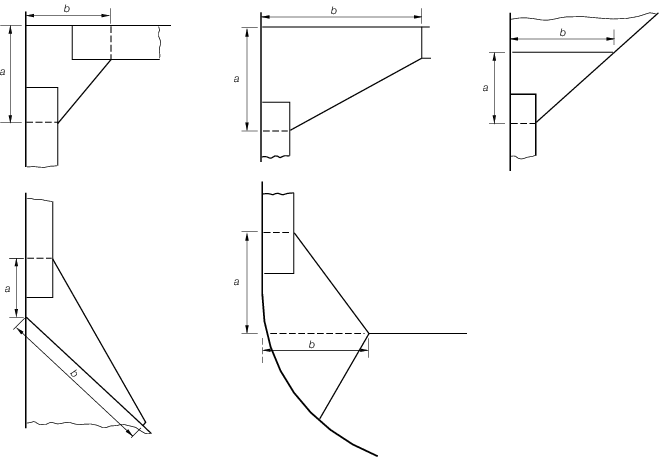
Figure 10.3.1 Diagrammatic arrangements of stiffener end brackets
Table 10.3.1 Thickness of brackets
| Bracket
|
Thickness, in mm
|
Limits
|
|
|
|
Minimum
|
Maximum
|
| With edge stiffened:
|
|
|
|
|
|
(a) in dry spaces
|

|
6,5
|
|
12,5
|
|
(b) in tanks
|

|
7,5
See Note
|
|
13,5
|
|
Unstiffened brackets:
(a) in dry spaces
|

|
7,5
|
–
|
|
|
(b) in tanks
|

|
8,5
See Note
|
–
|
|
|
|
3.4.7 Where
the stiffening member is lapped on to the bracket, the length of overlap
is to be adequate to provide for the required area of welding. In
general, the length of overlap should be not less than  , or the depth of stiffener, whichever is the greater. , or the depth of stiffener, whichever is the greater.
3.4.8 Where
the free edge of the bracket is hollowed out, it is to be stiffened
or increased in size to ensure that the modulus of the bracket through
the throat is not less than that of the required straight edged bracket.
3.5 Arrangements and details
3.5.1 The
arrangement of the connection between the stiffener and the bracket
is to be such that at no point in the connection is the modulus reduced
to less than that of the stiffener with associated plating.
3.5.2 The
design of end connections and their supporting structure is to be
such as to provide adequate resistance to rotation and displacement
of the joint.
3.5.3 For
arrangements where end brackets are not perpendicular to the adjacent
plating the strength of the brackets, in terms of lateral stability,
may need to be specially considered.
|
| Copyright 2022 Clasifications Register Group Limited, International Maritime Organization, International Labour Organization or Maritime
and Coastguard Agency. All rights reserved. Clasifications Register Group Limited, its affiliates and subsidiaries and their respective
officers, employees or agents are, individually and collectively, referred to in this clause as 'Clasifications Register'. Clasifications
Register assumes no responsibility and shall not be liable to any person for any loss, damage or expense caused by reliance
on the information or advice in this document or howsoever provided, unless that person has signed a contract with the relevant
Clasifications Register entity for the provision of this information or advice and in that case any responsibility or liability is
exclusively on the terms and conditions set out in that contract.
|
 |
|