
Section
10 Construction details and minimum thickness
10.1 Symbols
10.1.1 The
symbols used in this Section are defined as follows:
For the primary member:
|
d
w
|
= |
depth of member web, in mm |
|
s
t
|
= |
spacing of tripping or docking brackets on the web of the member,
in metres |
|
t
w
|
= |
thickness of member web, in mm |
|
S
w
|
= |
spacing of members, in metres |
For the primary member web stiffener:
|
d
|
= |
depth
of web plate panel, in mm |
|
ls
|
= |
span
of stiffeners between effective support points, in metres |
|
s
|
= |
spacing
of stiffeners on the web, in mm |
|
A
s
|
= |
cross-sectional area of the web stiffener and associated web
plating, in cm2
|
 s s
|
= |
moment
of inertia of the web stiffener and associated web plating, in cm4
|
For the primary member end bracket, see
Figure 9.10.2 Primary member end brackets:
|
d
b
|
= |
arm length, in metres |
|
lb
|
= |
effective
length of the free edge, in metres |
|
t
b
|
= |
thickness of the end bracket plating, in mm |
|
A
b
|
= |
cross-sectional area of the end bracket edge stiffeners and
associated plating, in cm2
|
 b b
|
= |
moment
of inertia of the end bracket edge stiffeners and associated plating,
in cm4
|
Other symbols are defined in Pt 4, Ch 9, 1.5 General definitions and symbols.
10.2 Compartment minimum thickness
10.2.1 Within
the cargo tank region, including wing ballast tanks and cofferdams
at the ends of or between cargo tanks, the thickness of primary member
webs and face plates, hull envelope and bulkhead plating is to be
not less than:
t = 2,15L
0,3 mm, or
t = 7,5 mm
whichever is the greater.
10.2.2 The
minimum thickness of secondary members is to be determined as above,
but need not exceed 11,0 mm.
10.2.3 In
pump-rooms the minima apply to shell, deck, longitudinal bulkhead
and associated longitudinals. For other items solely within the pump-room,
including transverse bulkheads separating the adjacent machinery spaces
from the pump-room, the minima may be reduced by 1,0 mm, subject to
a lower limit of 7,5 mm.
10.3 Geometric properties and proportions of members
10.3.1 The
depth of the web of any primary member is to be not less than 2,5
times the depth of the cut-outs for the passage of secondary members,
except where compensation is arranged to provide satisfactory resistance
to deflection and shear buckling in the web.
10.3.2 The
area of material in the face plate of any primary member structure
is not to exceed:
0,00667d
w
t
w cm2
nor is it to be less than:
0,00417s
t
d
w cm2.
10.3.3 The
geometric properties of rolled stiffeners and built sections are to
be calculated in association with an effective width of attached plating
in accordance with Pt 3, Ch 3, 3 Structural idealisation.
10.4 Continuity of primary members
10.4.1 Primary
members are to be so arranged as to ensure effective continuity of
strength throughout the range of tank structure. Abrupt changes of
depth or section are to be avoided. Where members abut on both sides
of a bulkhead or on other members, arrangements are to be made to
ensure that they are in alignment.
10.4.2 The
members are to have adequate end fixity, lateral support and web stiffening,
and the structure is to be arranged to minimise hard spots or other
sources of stress concentration. Openings are to have well rounded
corners and smooth edges and are to be located having regard to the
stress distribution and buckling strength of the plate panel.
10.5 Primary member web plate stiffening
10.5.1 The
webs of primary members are to be supported and stiffened in accordance
with the following requirements, which are designated as requirements
`A', `B', `C', `D' and `E'. The application of these requirements
is detailed in Pt 4, Ch 9, 10.7 Application of stiffening requirements, and the
corresponding locations indicated in Figure 9.10.1 Key to application requirements. Where webs are slotted for the passage of secondary
members, the web stiffeners are to be arranged to provide adequate
support for the loads transmitted, see
Pt 3, Ch 10, 5.2 Arrangements at intersections of continuous secondary and primary members. Where direct calculations
are carried out in accordance with Pt 4, Ch 9, 1.1 General 1.1.8 and Pt 4, Ch 9, 14 Direct calculations, other
stiffening arrangements will be accepted subject to compliance with
the maximum permissible stress and plate panel buckling criteria given
in the ShipRight SDA Procedure, Guidance Notes on Direct Calculations:
Primary Structure of Tankers.
10.5.2 Where
higher tensile steel is used for the primary members, the maximum
spacing of stiffeners given in this Section is to be multiplied by  . .
10.5.4 For
requirement `A' stiffening:
-
The thickness, t
w of the web is to be not less than 
-
Stiffening is
generally to be fitted normal to the face plate of the member, but
the stiffeners parallel to the face plate will be required when the
web depth, d
w, exceeds a value, d
max which is to be taken as:
for s ≤ 55t
w

for s > 55t
w

-
Where stiffening
parallel to the face plate is required, the distance from the face
plate of the member to the nearest stiffener is not to exceed 65t
w. Further stiffeners are to be fitted at similar spacing so
that the distance between the last stiffener and the shell or bulkhead
plating does not exceed d
max. In way of end
brackets to transverse bulkhead primary structure, stiffeners are
to be fitted normal to the face plate of the member so that web plate
panel dimensions parallel to the face plate do not exceed 80t
w.
10.5.5 For
requirement `B' stiffening:
-
The thickness, t
w of the web is to be not less than 
-
Stiffening is
generally to be fitted normal to the face plate of the member, but
stiffeners parallel to the face plate will be required when the web
depth, d
w, exceeds a value d
max, which is to be taken as:
for s ≤ 70t
w

for s > 70t
w

-
Where stiffening
parallel to the face plate is required, the distance from the face
plate of the member to the nearest stiffener is not to exceed 80t
w. Further stiffeners are to be fitted at similar spacing so
that the distance between the last stiffener and the shell or bulkhead
plating does not exceed d
max.
10.5.6 For
requirement `C' stiffening:
-
Stiffening is
generally to be fitted normal to the face plate of the member in line
with alternate secondary members, but stiffeners parallel to the face
plate will be required, when the web depth, d
w exceeds
a value, d
max which is to be taken as:
for s ≤ 76t
w

for s > 76t
w

-
Where stiffening
parallel to the face plate is required, the distance from the face
plate of the member to the nearest stiffener is not to exceed 90t
w. Further stiffeners are to be fitted at similar spacing so
that the distance between the last stiffener and the deck plating
does not exceed d
max.
10.5.7 For
requirement `D' stiffening:
-
Stiffening parallel
to the face plate will be required such that the distance between
the stiffener and face plate, or between two stiffeners, does not
exceed:
80t
w where L ≤ 90 m
55t
w where L ≥ 190 m
with intermediate values by interpolation.
-
Brackets are
to be fitted to support the face plates and stiffeners.
10.5.8 For
requirement `E' stiffening:
-
Stiffening parallel
to the face plate will be required such that the distance between
the stiffener and face plate, or between two stiffeners, does not
exceed:
85t
w where L ≤ 90 m
60t
w where L ≥ 190 m
with intermediate values by interpolation.
-
Brackets are
to be fitted to support the face plates and stiffeners.
10.6 Inertia and dimensions of stiffeners
10.6.2 Where
stiffeners are fitted in both directions, the inertia of the stiffeners
parallel to the face plate of the member is to be not less than that
of the stiffeners fitted normally.
10.6.3 The
depth of web stiffeners is to be not less than 75 mm.
10.6.4 Where
flat bar stiffeners are used, the ratio of depth to thickness is not
to exceed 18  . .
10.7 Application of stiffening requirements
10.7.1 The
requirements as detailed in Pt 4, Ch 9, 10.5 Primary member web plate stiffening and Pt 4, Ch 9, 10.6 Inertia and dimensions of stiffeners are to be applied in the following
locations, see also
Figure 9.10.1 Key to application requirements.
-
For transverses
at longitudinal bulkhead:
Requirement `A' stiffening is to extend at least as far as the
lower surface of the lower cross-tie. Elsewhere, requirement `B' stiffening
is to be fitted.
-
For deck transverses:
Requirement `C' stiffening is to be fitted.
-
For stringers
and horizontal girders on bulkheads:
Requirement `A' stiffening is to extend for a distance from
each end of 20 per cent of the span of the stringer or girder, but
at least beyond the toes of the end brackets. Elsewhere, requirement
`B' stiffening is to be fitted.
-
For cross-ties:
Cross-ties are to be suitably stiffened to prevent buckling
and twisting. Requirement `D' stiffening is to be fitted to the lower
or to a single cross-tie. Requirement `E' stiffening is to be fitted
to the upper cross-ties where two cross-ties are arranged.
-
For shell stringers
and vertical webs in fore peak:
Requirement `A' stiffening is to extend the full length of the
member.
10.7.2 The
application of stiffening requirements to transverse structures where
no cross-ties are fitted and within double hull structures are to
be based on the results of direct calculation and will be specially
considered.
10.8 Stiffening of continuous longitudinal girders
10.8.1 The
webs of continuous longitudinal deck and double bottom girders are
to be stiffened longitudinally. Particular attention is to be given
to the stiffening of docking girders, see also the buckling
requirements in Pt 3, Ch 4, 7 Hull buckling strength.
Table 9.10.2 Coefficients for stiffener
inertia
Aspect ratio of
plate panel,
|
1,0 or
more
|
0,9
|
0,8
|
0,7
|
0,6
|
0,5
|
0,4
|
0,3 or
less
|
|
p
|
1,5
|
2,1
|
2,9
|
4,2
|
6,1
|
9,2
|
14,6
|
30,0
|
Note
1. Intermediate values by
interpolation.
Note
2. The depth of panel, d, used in
calculating aspect ratio may be measured from the face of the
secondary member to which the primary member web stiffener is
attached.
|
10.8.2 The
stiffeners on deck girders are to be spaced not more than 55t
w mm apart except in way of vertical webs and end brackets,
where the spacing is not to exceed 45t
w mm.
Alternatively, a combination of parallel stiffeners at 55t
w mm spacing and normal stiffeners at 45t
w mm
spacing may be adopted. Particular attention is to be given to the
stiffening of the docking girder.
10.9 Stiffening of vertical webs on transverse bulkheads
10.9.1 Vertical
webs are to be fitted with stiffeners parallel to the face plate of
the web and spaced not more than 60t
w mm apart.
Stiffeners normal to the face plate are to be fitted when a vertical
web supports horizontal stiffeners on transverse bulkheads. The length
of stiffener is to be sufficient to distribute the load transmitted,
and the connection between web stiffener and bulkhead stiffener is
to comply with the relevant requirements of Pt 3, Ch 10, 5.2 Arrangements at intersections of continuous secondary and primary members.
10.10 Double bottom girders in way of docking supports
10.10.1 Additional
vertical stiffeners may be required on the bottom panels of the girder
to resist docking pressures.
10.11 Lateral stability of primary members
10.11.1 Tripping
brackets are generally to be fitted close to the toes of end brackets,
in way of cross-ties and elsewhere, so that the spacing between brackets
does not exceed the lesser of 4,5 m or 15 times the width of the face
plate (20 times in the case of deck transverses). Arrangements in
way of the intersections of primary members are to be such as to prevent
tripping. A closer spacing of brackets may be required to be adopted
with asymmetrical face plates.
10.11.2 To
maintain continuity of strength, substantial horizontal and vertical
brackets are to be fitted to transverses or stringers at ends of cross-ties.
Horizontal brackets are to be aligned with the cross-tie face plates,
and vertical end brackets are to be aligned with the cross-tie web.
10.11.3 Wide
face plates may require additional support between brackets.
10.11.4 In
the fore peak tank, if the angle between the normal to the shell plating
and the vertical webs exceeds 20°, tripping brackets are to be
fitted at the toes of end brackets and elsewhere, such that their
spacing does not exceed 3 m.
10.12 Openings in web plating
10.12.1 Where
openings are cut in the webs of primary supporting members, the greatest
dimension of the opening is not to exceed 20 per cent of the web depth.
The openings are to be kept equidistant from the corners of notches
for frames and stiffeners. In the case of webs supporting single skin
structures the openings are to be located so that the edges are not
less than 40 per cent of web depth from the face plate. Openings are
to be suitably framed where required.
10.12.2 In
way of cross-ties and their end connections lightening holes are not
to be cut in horizontal girders on the ship's side and longitudinal
bulkheads, in symmetrical webs nor in vertical webs on longitudinal
bulkheads and wing ballast tanks.
10.12.3 Holes
cut in primary longitudinal members within 0,1D of the
deck and bottom are, in general, to be reinforced as required by Pt 4, Ch 9, 4.10 Deck openings. Access holes may be cut in
deep transverses and girders with suitable compensation to provide
satisfactory resistance to deflection and shear buckling in the web.
10.12.4 All
holes are to have smooth edges and are to be kept well clear of notches
and the toes of brackets.
10.12.5 Small
air and drain holes cut in primary members are to be kept clear of
the toes of brackets and are to be well rounded with smooth edges.
Where holes are cut in primary longitudinal members in areas of high
stress, or where primary members are of higher tensile steel, they
are to be elliptical, or equivalent, to minimise stress concentration.
10.12.6 Where
holes are cut for heating coils, the lower edge of the hole is to
be not less than 100 mm from the inner bottom. Where large notches
are cut in the transverses for the passage of longitudinal framing,
adjacent to openings for heating coils, the longitudinal notches are
to be collared. Examination of the buckling strength of the web plate
panel between notches for longitudinals may be required.
10.13 Brackets connecting primary members
10.13.1 The
arm length of brackets connecting primary supporting members should,
in general, be not less than the depth of the member web, nor exceed
1,5 times the web depth. The two arms should be of approximately equal
lengths.
10.13.2 In
a ring system where the end bracket is integral with the webs of the
members, and the face plate is carried continuously along the edges
of the members and the bracket, the full area of the largest face
plate is to be maintained to the mid-point of the bracket and gradually
tapered to the smaller face plates. Butts in face plates are to be
kept well clear of the toes of brackets. Where a wide face plate abuts
on a narrower one, the taper is generally not to exceed 1 in 4. Where
a thick face plate abuts against a thinner one, if the difference
in thickness exceeds 3 mm, the taper on thickness is not to exceed
1 in 3.
10.13.3 The
thickness of separate end brackets is generally to be not less than
that of the thicker of the primary member webs being connected, but
may be required to be increased locally at the toes. The bracket is
to extend to adjacent tripping brackets, stiffeners or other support
points. Bracket toes are to be well radiused. Where the bracket is
attached to a corrugated bulkhead, suitable arrangements are to be
made to dissipate the load at the bracket toe. Details of the welding
to be used is way of toes separate brackets are to be submitted, see
also
Pt 3, Ch 10, 5.1 Continuity and alignment 5.1.7.
10.13.4 Brackets
are to be fitted with suitable face plates and stiffeners. The maximum
distance from the face plate to the first parallel stiffener is to
be 30t
b. Subsequent stiffeners lying parallel
to the face may be spaced not more than 45t
b apart.
The maximum arm length for an unstiffened triangular panel is 100t
b, see
Figure 9.10.2 Primary member end brackets.
The depth of stiffeners is to be not less than 75 mm, and their moment
of inertia is to comply with 10.6.
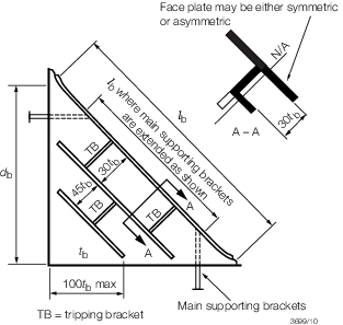
Figure 9.10.2 Primary member end brackets
10.13.5 The
area of discontinuous face plates is generally to be about 80 per
cent of the area of the face plates of the adjacent members. However,
where the stiffener adjacent to the face plate is of increased size,
consideration will be given to the face area required. In addition,
the following expression is to be satisfied:
10.13.6 The
ends of discontinuous face plates are to be well tapered. The taper
may be 1 in 3, but where the width of the face plate exceeds 500 mm,
a taper not less than 1 in 4 is generally to be adopted. Stiffeners
adjacent to the face plate should be tapered 1 in 2, and other stiffeners
may be cut at 45°.
10.13.8 In
the case of very large brackets with heavy face plates, it is recommended
that the effective span, l
b, be reduced by
extending the primary member main supporting brackets to provide lateral
stability to the face plate, see
Figure 9.10.2 Primary member end brackets.
10.14 Arrangements at intersections of continuous secondary and primary
members
|