
Section
5 Structural details
5.1 Continuity and alignment
5.1.1 The
arrangement of material is to be such as will ensure structural continuity.
Abrupt changes of shape or section, sharp corners and points of stress
concentration are to be avoided.
5.1.2 Where
members abut on both sides of a bulkhead or similar structure, care
is to be taken to ensure good alignment.
5.1.3 Pillars
and pillar bulkheads are to be fitted in the same vertical line wherever
possible, and elsewhere arrangements are to be made to transmit the
out of line forces satisfactorily. The load at head and heel of pillars
is to be effectively distributed and arrangements are to be made to
ensure the adequacy and lateral stability of the supporting members.
5.1.4 Continuity
is to be maintained where primary members intersect and where the
members are of the same depth, a suitable gusset plate is to be fitted.
5.1.5 End
connections of structural members are to provide adequate end fixity
and effective distribution of the load into the supporting structure.
5.1.6 The
toes of brackets, etc. should not land on unstiffened panels of plating.
Special care should be taken to avoid notch effects at the toes of
brackets, by making the toe concave or otherwise tapering it off.
5.1.7 Where
primary and/or secondary members are constructed of higher tensile
steel, particular attention is to be paid to the design of the end
bracket toes in order to minimise stress concentrations. Sniped face
plates which are welded onto the edge of primary member brackets are
to be carried well around the radiused bracket toe and are to incorporate
a taper not exceeding 1 in 3. Where sniped face plates are welded
adjacent to the edge of primary member brackets, adequate cross sectional
area is to be provided through the bracket toe at the end of the snipe.
In general, this area measured perpendicular to the face plate, is
to be not less than 60 per cent of the full cross-sectional area of
the face plate, see
Figure 10.5.1 Bracket toe construction. See
also
Pt 4, Ch 1, 4.3 Deck stiffening, Pt 4, Ch 1, 6.1 General, Pt 4, Ch 9, 5.7 Connections of longitudinals and Pt 4, Ch 9, 10.13 Brackets connecting primary members.
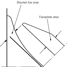
Figure 10.5.1 Bracket toe construction
5.2 Arrangements at intersections of continuous secondary and primary
members
5.2.1 Cut-outs
for the passage of secondary members through the web of primary members,
and the related collaring arrangements, are to be designed to minimise
stress concentrations around the perimeter of the opening and in the
attached hull envelope or bulkhead plating. The critical shear buckling
stress of the panel in which the cut-out is made is to be investigated.
Cut-outs for longitudinals will be required to have double lugs in
areas of high stress, e.g. in way of cross tie ends and floors under
bulkhead stools in ore and ballast holds.
5.2.2 Cut-outs
are to have smooth edges, and the corner radii are to be as large
as practicable, with a minimum of 20 per cent of the breadth of the
cut-out or 25 mm, whichever is the greater. It is recommended that
the web plate connection to the hull envelope or bulkhead should end
in a smooth tapered `soft toe'. Recommended shapes of cut-out are
shown in Figure 10.5.3 Cut-outs and connections, but
consideration will be given to other shapes on the basis of maintaining
equivalent strength and minimizing stress concentration. Consideration
is to be given to the provision of adequate drainage and unimpeded
flow of air and water when designing the cut-outs and connection details.
5.2.3 Asymmetrical
secondary members are to be connected on the heel side to the primary
member web plate. Additional connection by lugs on the opposite side
may be required.
5.2.4 Symmetrical
secondary members are to be connected by lugs on one or both sides,
as necessary.
5.2.5 The
cross-sectional areas of the connections are to be determined from
the proportion of load transmitted through each component in association
with its appropriate permissible stress.
5.2.7 This
load is to be apportioned between the connections as follows:
-
Transmitted through
the collar arrangement:
where A1 is derived in accordance with Pt 3, Ch 10, 5.2 Arrangements at intersections of continuous secondary and primary members 5.2.8 and  is not to be taken as greater than 0,25 is not to be taken as greater than 0,25
The collar load factor, C
f, is to be
derived as follows:
Symmetrical secondary members
|
C
f = 1,85
|
for A
f ≤ 18
|
|
C
f = 1,85 - 0,0341 (A
f -18)
|
for 18 < A
f ≤ 40
|
|
C
f = 1,1 - 0,01 (A
f - 40)
|
for A
f > 40
|
Asymmetrical secondary members
|
Cf
|
= |
0,68
+ 0,0224 
|
-
Transmitted through
the primary member web stiffener:
-
Where the web
stiffener is not connected to the secondary member, P
1 is
to be taken equal to P.
Table 10.5.1 Total load transmitted to
connection of secondary members
| Ship
type
|
Head, h
1, in metres
|
Total
load, P, transmitted to connection
|
| (1) Oil tankers, bulk chemical
tankers and combination carriers, see
Pt 3, Ch 10, 1.1 Application 1.1.3
|
h
1 = load height, in metres, derived in accordance with the
following provisions, but to be taken as not less than  or (0,01L
1 + 0,7) m whichever is the greater or (0,01L
1 + 0,7) m whichever is the greater
|
|
|
|
For shell framing members:
|
|
|
|
(a) With mid-point of span at base line, h
1 = 0,8D
2
|
|
|
|
|
|
|
|
(b) With mid-point of span at a distance 0,6D
2 above base line, h
1 = f
D
2
B
f
|
|
|
|
(c) With mid-point of span intermediate between (a) and (b). The
value of h
1 is to be obtained by linear interpolation between values from
(a) and (b).
|
(a) In general
|
P |
= |
10,06 (S
w - s
1/2) s
1
h
1 kN |
|
|
|
(d) With mid-point of span higher than 0,6D
2 above base line.
|
(b) For wash bulkheads
|
|
|
The value of h
1 is to be obtained by linear interpolation between the values
from (b) and the values at the following points:
|
|
P |
= |
11,77 (S
w - s
1/2) s
1
h
1 kN |
|
|
|
(i) For
framing members located at and abaft 0,2L from the forward
perpendicular (see
Figure 10.5.2 Load height diagrams for framing members (a) at and abaft 0,2L from
the forward perpendicular and (b) forward of cargo tank region for oil tankers,
bulk chemical tankers and combination carriers (see
Pt 3, Ch 10, 1.1 Application 1.1.3) and forward of 0,15L from the forward
perpendicular for other ship types)
|
Zero value
at the level of the deck edge amidships
|
|
|
|
(ii) For
framing members forward of cargo tank region (see Fig. 10.5.2(b))
|
Value of
f
D
2 (B
f - 1) at the level 3 m above the minimum bow height determined
from the Load Lines Convention
|
|
|
|
(iii) Intermediate values between locations (i) and
(ii) are to be determined by linear interpolation
|
|
|
|
For secondary stiffening members of transverse and
longitudinal bulkheads, and inner hull an inner bottom of double hull
tankers, see
Pt 3, Ch 10, 1.1 Application 1.1.3:
|
|
|
|
|
h
1
|
= |
distance from the mid-point of span to top of tank but
need not exceed 0,8D
2
|
|
|
|
|
Side and bottom shell longitudinals
|
|
| (2) Other
ship types for which oil tanker (see
Pt 3, Ch 10, 1.1 Application 1.1.3) requirements are not applicable
|
As for (1) except as follows:
(a) h
1 to be derived in accordance with (1) above but to be taken
as not less than  m for type `B-60' and the greater of m for type `B-60' and the greater of  , or 1,20 m for Type 'B' ships , or 1,20 m for Type 'B' ships
|
P = 10,06
(S
w - s
1/2) s
1
h
1kN
|
|
|
(b) h
1 for item (1)(d)(ii) above to extend forward of 0,15L
from the forward perpendicular
|
|
| (3) Other ship types for which oil
tanker (see
Pt 3, Ch 10, 1.1 Application 1.1.3) requirements are not applicable
(continued)
|
Internal tank boundaries
(a) Topside tank longitudinals
h
1 = distance from the longitudinal under consideration to the
highest point of the tank with the ship inclined 30° either way,
or
= the greater of the distance from the longitudinal under
consideration to the top of the tank, or half the distance to the top of
the overflow, or
= 1,5 m
= whichever is the
greatest
|
P = 10,06 (S
w - s
1/2) s
1
h
1kN
|
|
|
(b) Inner bottom and hopper longitudinals
|
P = 9,81 (S
w - s
1/2) s
1
h
1/C kN
|
|
|
|
= but not to be taken
less than the load derived from (b)(iv), (b)(v), (b)(vi) or (c) where
applicable
|
|
|
(i) For cargo ships and bulk carriers (see
Pt 3, Ch 10, 1.1 Application 1.1.3) without the notation ‘strengthened for
heavy cargoes’
h
1 = 1,39T
|
|
|
|
(ii) For cargo ships and bulk carriers (see
Pt 3, Ch 10, 1.1 Application 1.1.3) with the notation ‘strengthened for
heavy cargoes’ h
1 = H
|
|
|
|
(iii) For longitudinal bulkheads of ore carriers
h
1 = H
K
c
|
|
|
|
(iv) For bulk carriers (see
Pt 3, Ch 10, 1.1 Application 1.1.3) where the topside wing tank is
interconnected with hopper side and double bottom tanks h
1 = the distance from the longitudinal under consideration to the
top of the topside tank with the ship inclined 25° either way
|
P = 10,06 (S
w - s
1/2) s
1
h
1kN
|
|
|
(v) For bulk carriers (see
Pt 3, Ch 10, 1.1 Application 1.1.3) in way of ballast hold h
1 = the distance from the longitudinal under consideration to the
top of the hatchway coaming
|
P = 10,06 (S
w - s
1/2) s
1
h
1kN
|
|
|
(vi) For cargo ships and bulk carriers (see
Pt 3, Ch 10, 1.1 Application 1.1.3) with double hull where tank at side
interconnected with double bottom h
1 = H
|
P = 10,06 (S
w - s
1/2) s
1
h
1kN
|
|
|
|
|
|
|
(c) Longitudinals of inner hull of double hull cargo ships and
bulk carriers (see
Pt 3, Ch 10, 1.1 Application 1.1.3)
|
P = 10,06 (S
w - s
1/2) s
1
h
1kN
|
|
|
h
1 = the distance from the longitudinal under consideration to the
top of the tank, or half the distance to the top of the overflow, whichever
is the greater
|
|
|
|
|
|
|
|
|
C
|
= |
stowage rate, in m3 /tonne, as defined in
Pt 3, Ch 3, 5.2 Symbols. For cargo ships without the
notation ‘strengthened for heavy cargoes’, the value to be used is
1,39 m3/tonne. For cargo ships and bulk carriers
(see
Pt 3, Ch 10, 1.1 Application 1.1.3) with the notation
‘strengthened for heavy cargoes’, the actual stowage rate is to be
used, but the value is not to be taken greater than 0,865
m3/tonne |
|
|
H
|
= |
height from inner bottom at position under
consideration, to deck at side amidships, in metres, for inner
bottom longitudinals |
| = |
height from the longitudinal under consideration to
the underside of the topside tank sloped bulkhead, in metres, for
hopper longitudinals |
|
|
S
w
|
= |
spacing of primary members, in metres |
|
|
s
1
|
= |
spacing of secondary members, in metres |
|
|
T
|
= |
the summer draught, in metres, measured from top of
keel |
|
|
D
2
|
= |
D in metres, but need not be taken greater than 1,6T
|
|
|
L
1
|
= |
L but need not be taken as greater than 190 m |
|
|
|
Table 10.5.2 Load height factor, f
|
|
Ship depth, D metres
|
|
|
≤17,5
|
20
|
22.5
|
25
|
27.5
|
30
|
| (1)
|
(a) For oil tankers, bulk chemical tankers and combination
carriers (see
Pt 3, Ch 10, 1.1 Application 1.1.3), tank boundaries wholly within parallel
mid-body
|
0,6
|
0,6
|
0,582
|
0,556
|
0,535
|
0,517
|
|
|
(b) For other ship types, at an abaft of
0,2L from the forward perpendicular
|
| (2)
|
(a) For oil tankers, bulk chemical tankers and combination
carriers (see
Pt 3, Ch 10, 1.1 Application 1.1.3), tank boundaries wholly or partially
outside parallel mid-body
|
0,7
|
0,685
|
0,685
|
0,628
|
0,6
|
0,577
|
|
|
(b) For other ship types, forward of 0,15L
from the forward perpendicular
|
Note Intermediate values to be obtained by linear
interpolation
|
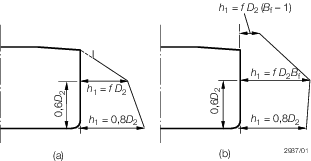
Figure 10.5.2 Load height diagrams for framing members (a) at and abaft 0,2L from
the forward perpendicular and (b) forward of cargo tank region for oil tankers,
bulk chemical tankers and combination carriers (see
Pt 3, Ch 10, 1.1 Application 1.1.3) and forward of 0,15L from the forward
perpendicular for other ship types
5.2.8 The
effective cross-sectional area A
1 of the collar
arrangements is to be taken as the sum of cross-sectional areas of
the components of the connection as follows:
-
Direct connection:
-
Lug connection:
- where
|
f
1
|
= |
1,0 for symmetrical secondary member connections |
|
|
= |
 but not greater than 1,0, for asymmetrical secondary member
connections but not greater than 1,0, for asymmetrical secondary member
connections
|
|
t
w
|
= |
thickness of primary member web, in mm |
|
t
2
|
= |
thickness, in mm, of lug connection, and is to be taken not
greater than the thickness of the adjacent primary member web plate |
|
W
|
= |
overall
width of the cut-out, in mm |
|
W
2
|
= |
width for cut-out asymmetrical to secondary member web, in mm |
see
Figure 10.5.3 Cut-outs and connections
5.2.10 Where
a bracket is fitted to the primary member web plate in addition to
a connected stiffener it is to be arranged on the opposite side to,
and in alignment with the stiffener. The arm length of the bracket
is to be not less than the depth of the stiffener, and its cross-sectional
area through the throat of the bracket is to be included in the calculation
of A
f.
5.2.11 In
general where the primary member stiffener is connected to the secondary
member it is to be aligned with the web of the secondary member, except
where the face plate of the latter is offset and abutted to the web,
in which case the stiffener connection is to be lapped. Lapped connections
of primary member stiffeners to mild steel bulb plate or rolled angle
secondary members may also be permitted. Where such lapped connections
are fitted, particular care is to be taken to ensure that the primary
member stiffener wrap around weld connection is free from undercut
and notches, see also
Pt 3, Ch 10, 2.9 Inspection of welds.
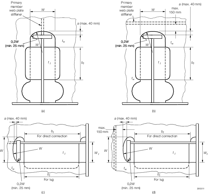
Figure 10.5.3 Cut-outs and connections
5.2.12 Fabricated
longitudinals having the face plate welded to the underside of the
web, leaving the edge of the web exposed, are not recommended for
side shell and longitudinal bulkhead longitudinals. Where it is proposed
to fit such sections, a symmetrical arrangement of connection to transverse
members is to be incorporated. This can be achieved by fitting backing
brackets on the opposite side of the transverse web or bulkhead. The
primary member stiffener and backing brackets are to be lapped to
the longitudinal web, see
Pt 3, Ch 10, 5.2 Arrangements at intersections of continuous secondary and primary members 5.2.11.
5.2.13 For
ship types for which oil tanker (see
Pt 3, Ch 10, 1.1 Application 1.1.3) requirements are not applicable,
the collar arrangement is to satisfy the requirements of Pt 3, Ch 10, 5.2 Arrangements at intersections of continuous secondary and primary members 5.2.1 to Pt 3, Ch 10, 5.2 Arrangements at intersections of continuous secondary and primary members 5.2.12 inclusive. In addition
the weld area of the connections is to be not less than the following:
-
Connection of
primary member stiffener to the secondary member:
|
A
w
|
= |
0,25 A
f or 6,5 cm2, whichever
is the greater, corresponding to a weld factor of 0,34 for the throat
thickness
|
-
Connection of
secondary member to the web of the primary member:
|
A
w
|
= |
 corresponding to a weld factor of 0,34 in tanks or 0,27
in dry spaces for the throat thickness corresponding to a weld factor of 0,34 in tanks or 0,27
in dry spaces for the throat thickness
|
- where
|
A
w
|
= |
weld area, in cm2, and is calculated as total length
of weld, in cm, multiplied by throat thickness, in cm
|
|
A
f
|
= |
cross-sectional area of the primary member web stiffener, in
cm2, in way of connection
|
|
Z
|
= |
the
section modulus, in cm3, of the secondary member.
|
Table 10.5.3 Permissible stresses
| Item
|
Direct stress, in N/mm2
(see Notes 1 and 2)
|
Shear stress, in N/mm2
(see Note 1)
|
| Oil
tankers
|
Other ship
types for which oil tanker requirements are not applicable
|
Oil tankers
and ship types where primary member stiffener unconnected
|
Other ship
types for which oil tanker requirements are not applicable
|
| Primary member web plate stiffener within distance a of
end see
Figure 10.5.3 Cut-outs and connections
|
147,2
|
157
|
—
|
—
|
|
|
Butted
|
98,1
(double continuous fillet)
|
117,7
(double continuous fillet)
|
—
|
—
|
| Welding of primary member web plate
stiffener to secondary member
|
147,2
(automatic deep penetration)
|
157
(automatic deep penetration)
|
—
|
—
|
|
|
Lapped
|
—
|
—
|
83,4
See Note 2
|
98,1
See Note 2
|
| Lug or collar plate and weld
|
Single
|
—
|
—
|
68,6
|
98,1
|
| Double
|
—
|
—
|
83,4
See Note 3
|
Note 3. When the permissible shear stress is applied in the assessment for
the notation Strengthened to carry cargoes which may liquefy (IMSBC
Group A), the permissible shear stress shall be divided by
k, see
Pt 3, Ch 2, 1.2 Steel 1.2.3, i.e.
83,4/ k N/mm 2.
|
5.2.15 Alternative
arrangements will be considered on the basis of their ability to transmit
load with equivalent effectiveness. Details of the calculations made
and testing procedures are to be submitted.
5.3 Openings
5.3.1 Manholes,
lightening holes and other cut-outs are to be avoided in way of concentrated
loads and areas of high shear. In particular, manholes and similar
openings are not to be cut in vertical or horizontal diaphragm plates
in narrow cofferdams or double plate bulkheads within one-third of
their length from either end, nor in floors or double bottom girders
close to their span ends, or below the heels of pillars, unless the
stresses in the plating and the panel buckling characteristics have
been calculated and found satisfactory.
5.3.2 Manholes,
lightening holes and other openings are to be suitably framed and
stiffened where necessary.
5.3.3 Air
and drain holes, notches and scallops are to be kept at least 200
mm clear of the toes of end brackets and other areas of high stress.
Openings are to be well rounded with smooth edges. Details of scalloped
construction are shown in Figure 10.2.1 Weld dimensions and types.
Closely spaced scallops are not permitted in higher tensile steel
members. Widely spaced air or drain holes may be accepted, provided
that they are of elliptical shape, or equivalent, to minimise stress
concentration and are, in general, cut clear of the weld connection.
5.4 Sheerstrake and bulwarks
5.4.1 Where
an angled gunwale is fitted, the top edge of the sheerstrake is to
be kept free of all notches and isolated welded fittings. Bulwarks
are not to be welded to the top of the sheerstrake within the 0,5L amidships.
5.4.2 Where
a rounded gunwale is adopted, the welding of fairlead stools and other
fittings to this plate is to be kept to the minimum, and the design
of the fittings is to be such as to minimise stress concentration.
5.4.3 Arrangements
are to ensure a smooth transition from rounded gunwale to angled gunwale
towards the ends of the ship.
5.4.4 At
the ends of superstructures where the side plating is extended and
tapered to align with the bulwark plating, the transition plating
is to be suitably stiffened and supported. Where freeing ports or
other openings are essential in this plate, they are to be suitably
framed and kept well clear of the free edge.
5.5 Fittings and attachments, general
5.6 Bilge keels and ground bars
5.6.1 It
is recommended that bilge keels should not be fitted in the forward
0,3L region on ships intended to navigate in severe ice
conditions.
5.6.2 Bilge
keels are to be attached to a continuous ground bar as shown in Figure 10.5.5 Bilge keel construction. Butt welds in shell
plating, ground bar and bilge keels are to be staggered.
5.6.3 The
minimum thickness of the ground bar is to be equal to the thickness
of the bilge strake or 14 mm, whichever is the lesser.
5.6.5 The
ground bar is to be connected to the shell with a continuous fillet
weld and the bilge keel to the ground bar with a light continuous
fillet weld.
5.6.6 Direct
connection between ground bar butt welds and shell plating, and between
bilge keel butt welds and ground bar is to be avoided.
5.6.7 The
design of single web bilge keels is to ensure that failure to the
web occurs before failure of the ground bar. In general, this may
be achieved by ensuring the web thickness of bilge keels does not
exceed that of the ground bar.
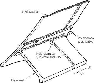
Figure 10.5.5 Bilge keel construction
5.6.11 An
internal transverse support is to be positioned as close as possible
to halfway between the end of the bilge keel web and the end of the
ground bar, see
Figure 10.5.6 Bilge keel end design.
5.6.13 For
ships over 65 m in length, holes are to be drilled in the bilge keel
butt welds. The size and position of these holes are to be as illustrated
in Figure 10.5.5 Bilge keel construction. Where the
butt weld has been subject to non-destructive examination the stop
hole may be omitted.
5.6.15 Within
zone 'B', (see
Figure 10.5.6 Bilge keel end design), welds at the end of the ground bar and bilge plating,
and at the end of the bilge keel web and ground bar, are to have weld
factors of 0,44 and 0,34 respectively. These welds are to be ground
and to blend smoothly with the base materials.
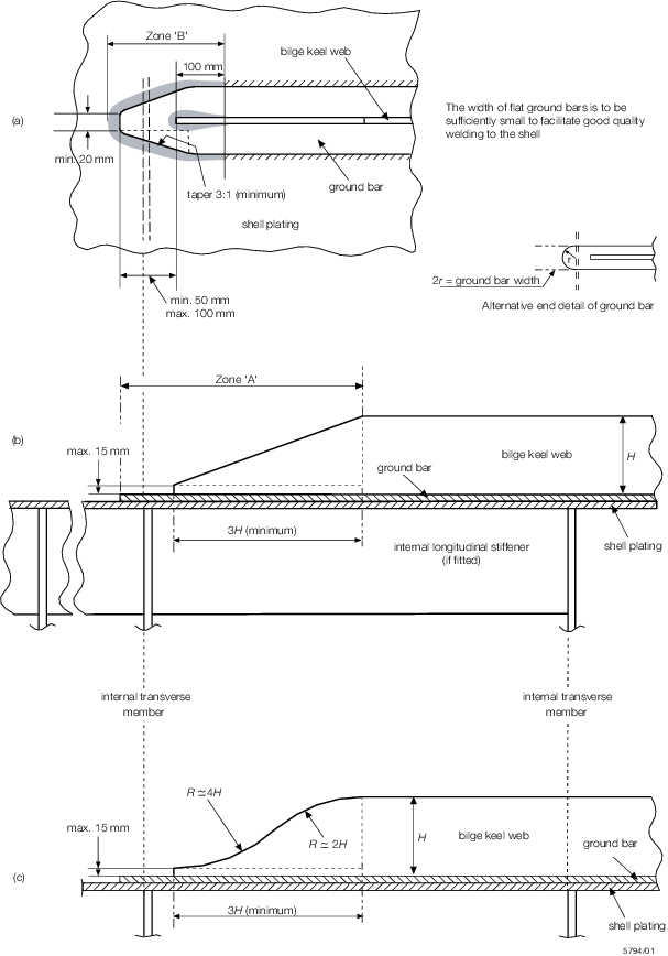
Figure 10.5.6 Bilge keel end design
5.6.16 A
plan of the bilge keels is to be submitted for approval of material
grades, welded connections and detail design.
5.7 Other fittings and attachments
5.7.1 Gutterway
bars at the upper deck are to be so arranged that the effect of main
hull stresses on them is minimised.
5.7.2 Minor
attachments, such as pipe clips, staging lugs and supports, are generally
to be kept clear of toes of end brackets, corners of openings and
similar areas of high stress. Where connected to asymmetrical stiffeners,
the attachments may be in line with the web providing the fillet weld
leg length is clear of the offset face plate or flange edge. Where
this cannot be achieved the attachments are to be connected to the
web, and in the case of flanged stiffeners they are to be kept at
least 25 mm clear of the flange edge. On symmetrical stiffeners, they
may be connected to the web or to the centreline of the face plate
in line with the web.
5.7.3 Where
necessary in the construction of the ship, lifting lugs may be welded
to the hull plating but they are not to be slotted through. Where
they are subsequently removed, this is to be done by flame or mechanical
cutting close to the plate surface, and the remaining material and
welding ground off. After removal the area is to be carefully examined
to ensure freedom from cracks or other defects in the plate surface.
|