
Section
5 Hull framing
5.1 General
5.1.1 In the
cargo tank region, the scantlings of deck, bottom and side longitudinals,
and of transverse side framing, where fitted, are to be in accordance
with the requirements of this Section.
5.2 Symbols
5.2.1 The
symbols used in this Section are defined as follows:
|
c
1
|
= |
 at deck at deck
|
|
|
= |
1,0 at 
|
|
|
= |
 at base line of ship at base line of ship
intermediate values
of c
1 by interpolation
|
|
c
2
|
= |
 at deck at deck
|
|
|
= |
1,0 at 
|
|
|
= |
 at base line of ship at base line of ship
intermediate values
of c
2 by interpolation
|
|
d
w
|
= |
depth of web, in mm |
|
h
|
= |
distance
of longitudinal below deck at side, in metres. For deck longitudinals, h = 0
|
|
h
o
|
= |
the distance, in metres, from the mid-point of span of the stiffener
to the highest point of tank, excluding hatchway |
|
h
1
|
= |
 , but in no case to be taken less than , but in no case to be taken less than  m or (0,01L
1 + 0,7) m, whichever
is the greater, and need not be taken greater than m or (0,01L
1 + 0,7) m, whichever
is the greater, and need not be taken greater than  for bottom longitudinals for bottom longitudinals
|
|
h
2
|
= |
distance, in metres, from mid-point of span of transverse side
frame to deck at side measured at mid-length of tank, but to be taken
not less than 2,5 m |
|
h
3
|
= |
h
0 + Rb
1, but
need not be taken greater than (0,75D + Rb
1) for bottom longitudinals
|
|
l
e
|
= |
effective length, in metres, of longitudinals measured between
span points, but to be taken not less than 1,5 m in double bottom
and 2,5 m elsewhere. For determination of span points, see
Pt 3, Ch 3, 3 Structural idealisation.
|
|
t
f
|
= |
thickness of flange, in mm |
|
t
s
|
= |
thickness of the bilge shell plating, in mm |
|
t
w
|
= |
thickness of web, in mm |
|
D1
|
= |
D, in metres, but is to be taken not less than 10 and need not
be taken greater than 16
|
|
|
= |
where θ is
the roll angle, in degrees |
|
|
= |
and 
|
Other symbols are defined in Pt 4, Ch 9, 1.5 General definitions and symbols
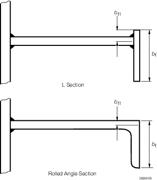
Figure 9.5.1 Definition of b
f and b
f1
5.3 Deck, side and bottom longitudinals
5.3.1 The
modulus of longitudinals within the cargo tank region, except as provided
for in Pt 4, Ch 9, 5.3 Deck, side and bottom longitudinals 5.3.2 and Pt 4, Ch 9, 5.5 Deck longitudinals outside 0,4L amidships is to be not less than the greater
of the following:
-
Z = 0,056s
kh
1
l
e
2
F
1
F
s cm3, or
-
Z = 0,0051s
kh
3
l
e
2
F
2 cm3
where F
1 and F
2 values
are as given in Table 9.5.1 Values of F1 and Table 9.5.2 Values of F2 and F
s is
a fatigue factor to be taken as follows:
|
F
s
|
= |
 at 0,6D above the base line at 0,6D above the base line
|
|
|
= |
1,0 at upper deck
at side and at the base line, intermediate values by linear interpolation |
For flat bars and bulb plates  may be taken as 0,5 may be taken as 0,5
The modulus of side longitudinals
need not exceed that of a bottom longitudinal having the same spacing
and configuration.
Table 9.5.1 Values of F
1
| Item
|
F
1
|
Deck longitudinals and side longitudinals
above 
|
|
Side longitudinal and bottom
longitudinals
below 
|
|
NOTE
Minimum F
1 = 0,12
|
Table 9.5.2 Values of F
2
| Item
|
F
2
|
Deck longitudinals and side
longitudinals
above 
|
|
Side longitudinal and bottom
longitudinals
below 
|
|
NOTE
Minimum F
2 = 0,73
|
5.3.4 Where
the spacing of transverses exceeds 5,5 m, the scantlings of side and
bottom longitudinals in way of bulkheads and primary members, including
end connections, are to be verified by direct calculation.
5.3.5 The
side and bottom longitudinal scantlings derived from Pt 4, Ch 9, 5.3 Deck, side and bottom longitudinals 5.3.1 and Pt 4, Ch 9, 5.3 Deck, side and bottom longitudinals 5.3.2, using the midship thickness
of plating, are to extend throughout the cargo tanks. Where the shell
plating is inclined at an angle to the horizontal longitudinal axis
of greater than 10°, the span of the longitudinals is to be measured
along the member. Where the shell plating is inclined at an angle
to the vertical axis of greater than 10°, the spacing of longitudinals
is to be measured along the chord between members. Where the angle
of attachment of side longitudinals clear of amidships varies by 20°
or more from a line normal to the plane of the shell, the properties
of the section are to be determined about an axis parallel to the
attached plating. Angles of slope greater than 40° are to be avoided.
5.3.6 Fabricated
longitudinals having the face plate welded to the underside of the
web, leaving the edge of the web exposed, are not recommended for
shell, inner hull or longitudinal bulkhead longitudinals. Where it
is proposed to fit such sections, a symmetrical arrangement of connection
to transverse members is to be incorporated. This can be achieved
by fitting backing brackets on the opposite side of the transverse
web or bulkhead. The primary member web stiffener and backing bracket
are to be lapped to the longitudinal. Recommended examples of such
backing structure can be seen in the ShipRight FDA Procedure,
Structural Detail Design Guide (SDDG).
5.3.7 Where
partial filling of the tanks is also contemplated the deck longitudinals
are to comply with the requirements of Pt 4, Ch 9, 6.1 General 6.1.2.
5.3.8 Stiffeners
and brackets on vertical webs in wing ballast tanks, where fitted
on one side and connected to higher tensile steel longitudinals between
the base line and 0,8D above the base line, are to have
their heels well radiused to reduce stress concentrations. Where a
symmetrical arrangement is fitted, i.e. bracket or stiffening on both
sides, and they are connected to higher tensile steel longitudinals,
the toes of the stiffeners or brackets are to be well radiused. Alternative
arrangements will be considered if supported by appropriate fatigue
life assessment calculations.
5.3.9 Where
higher tensile steel side longitudinals pass through transverse bulkheads
in the cargo area, well radiused brackets of the same material are
to be fitted on both the fore and after side of the connection between
the upper turn of bilge and 0,8D above the base line.
Particular attention should be given to ensuring the alignment of
these brackets. Alternative arrangements will be considered if supported
by appropriate fatigue life assessment calculations.
Table 9.5.3 Determination of b
1
| Item
No.
|
Structural arrangement
|
Location
|
Value
of b
1, metres
|
| 1
|
|
(a) Bottom longitudinals
|
The greater horizontal distance from ship side to
the longitudinal
|
|
|
Where wing and double bottom ballast
tanks port and starboard are interconnected
|
(b) Side longitudinals
|
Breadth of ship
|
|
|
|
(c) Deck longitudinals
|
(i) In way of cargo tanks and inboard
ballast tanks, the greater horizontal distance from tank corner at top of
tank to longitudinal, either side
|
|
|
|
|
(ii) In way of wing ballast tanks, the
greater horizontal distance from ship side to longitudinal, either
side
|
| 2
|
Where wing ballast tanks port and
starboard are separate
|
(a) Bottom
longitudinals
|
The
horizontal distance from ship side to longitudinal
|
| (b) Side longitudinals
|
Width of wing ballast tank
|
5.4 Bilge longitudinals and brackets
5.4.1 The
scantlings of bilge longitudinals are to be graduated between those
required for the bottom and lowest side longitudinals.
5.4.2 Where
bilge longitudinals are omitted, the spacing of transverses or equivalent
bilge brackets must not exceed:
Where no intermediate brackets are fitted between
transverses, the spacing between the two outermost bottom longitudinals
and between the two lowest side longitudinals is not to exceed one-third
of the bilge radius or 40 times the local shell thickness, whichever
is the greater.
5.5 Deck longitudinals outside 0,4L amidships
5.5.1 Within
the cargo tank region, deck longitudinals may be gradually tapered
outside 0,4L amidships in association with the deck plating,
on the basis of area and modulus. For the requirements, see
Pt 3, Ch 3, 2.5 Taper requirements for hull envelope and Table 3.2.1 Taper requirements for hull
envelope, see also
Pt 4, Ch 9, 5.3 Deck, side and bottom longitudinals 5.3.5.
5.5.2 The
midship spacing of longitudinals is, in general, to be maintained
throughout the cargo tank region. The plating thickness and longitudinal
depth and thickness are not to be increased at any point in the direction
of the taper of area towards the ends of the ship, other than as may
be required for compensation for openings. Changes of longitudinal
section are, in general, to be avoided.
5.5.4 Where
the spacing of transverses in cargo tanks is not constant and variations
in longitudinal scantlings are contemplated to suit differing spans,
individual consideration will be given to the taper arrangements.
5.6 Stability of longitudinals
5.6.1 The
lateral and torsional stability of longitudinals together with web
and flange buckling criteria are to be verified in accordance with Pt 3, Ch 4, 7 Hull buckling strength.
5.6.2 In addition,
the following requirements are to be satisfied:
-
Flat bar longitudinal
-
when continuous
at bulkheads
-
when non-continuous
at bulkheads
-
Built sections
-
-
 15 for asymmetric sections 15 for asymmetric sections
-
 30 for symmetric sections. 30 for symmetric sections.
5.7 Connections of longitudinals
5.7.1 Connections
of longitudinals to bulkheads are to provide adequate fixity and continuity
of longitudinal strength. See also the ShipRight
FDA Procedure, Structural Detail Design Guide (SDDG), for recommended
design details in critical areas.
5.7.2 Where
the length of the ship exceeds 150 m, the longitudinals within 0,1D of the bottom and deck are to be continuous through the transverse
bulkheads. Higher tensile steel longitudinals are to be continuous
irrespective of ship length. Alternative arrangements will be individually
considered.
5.8 Openings in longitudinals
5.8.1 In general,
closely spaced scallops are not permitted in longitudinals within
the range of cargo tanks except in way of ballast pipe suctions, reinforcement
in these areas will be specially considered.
5.8.2 Small
air and drain holes, cut-outs at erection butts and similar widely
spaced openings are, in general, to be not less than 200 mm clear
of the toes of end brackets, intersections with primary supporting
members and other areas of high stress. All openings are to be well
rounded with smooth edges.
5.8.3 Drain
holes in higher tensile steel longitudinals attached to higher tensile
steel plating are to be elliptical in shape or of equivalent design
to minimise stress concentrations. The opening is generally to be
located clear of the welded connection to the plating, but where a
flush opening is essential for drainage the weld connection is to
end in a soft toe.
5.8.4 Small
circular air holes may be arranged in higher tensile steel deck longitudinals.
5.8.5 Isolated
openings spaced greater than 1 metre apart need not be taken into
account in calculating the section modulus of the longitudinal, provided
that the depth does not exceed 10 per cent of the web depth, or 75
mm, whichever is the greater, but in no case more than 25 per cent
of the depth of the longitudinal.
5.9 Transverse side frames
5.9.2 The section modulus of transverse side frames is to be not less than:
Z = 0,01025ksh
2
l
e
2 cm3, where side webs are fitted;
or
Z = 0,012ksh
2
l
e
2 cm3, where side webs are not fitted.
5.9.5 The inertia of transverse side frames is to be not less than:
In the forward 0,15L:  = 3,5le
Z cm4 = 3,5le
Z cm4
Elsewhere:  = 3,2le
Z cm4. = 3,2le
Z cm4.
|