
Section
1 General
1.1 General
1.1.1 This
Chapter applies primarily to the arrangements and scantlings within
the cargo tank region of sea-going tankers having integral cargo tanks,
for the carriage of oil having a flash point not exceeding 60°C
(closed-cup test), in association with the class notation indicated
in Pt 4, Ch 9, 1.3 Class notation and applicable Rules for CSR Double Hull Oil Tankers 1.3.1 or Pt 4, Ch 9, 1.4 Class notation and applicable Rules for non-CSR Double Hull Oil Tankers 1.4.1. Except as indicated in Pt 4, Ch 9, 1.1 General 1.1.2, Pt 4, Ch 9, 1.1 General 1.1.3 and Pt 4, Ch 9, 1.1 General 1.1.4, the
cargo spaces are to be bounded by side and bottom dedicated water
ballast tanks or void spaces constituting a double hull for the ship, see
Table 9.1.1 Cargo tank boundary
requirements.
1.1.5 Where
only oils having flash points exceeding 60ºC are to be carried,
the Rule requirements and class notation will be modified accordingly
the additional class notation ‘F.P. exceeding 60ºC’
will be entered in the Register Book.
1.1.7 The scantlings and arrangements of tankers intended for cargoes other than
oil will be specially considered in relation to the characteristics of the cargo, and
the class notation will be modified accordingly. A full list of such cargoes for a
particular ship, with special requirements as applicable, can be provided by Lloyd’s
Register (hereinafter referred to as ‘LR’) on application. Chemical cargoes listed in
Chapter 18 of the Rules and Regulations for the Construction and Classification of
Ships for the Carriage of Liquid Chemicals in Bulk (hereinafter refered to as the
Rules for Ships of Liquid Chemicals) may be carried in ships for which the arrangements,
scantlings and materials comply with the requirements of that Chapter. Special
consideration will also be given to the carriage of cargoes with a relative density
greater than 1,025, see also
Pt 4, Ch 9, 1.3 Class notation and applicable Rules for CSR Double Hull Oil Tankers and
Pt 4, Ch 9, 1.4 Class notation and applicable Rules for non-CSR Double Hull Oil Tankers.
1.1.8 The Regulations for classification and assignment of the above notations
and other notations, as appropriate to the arrangements, scantlings and service are
provided for in Pt 1, Ch 2, 2 Character of classification and class notations.
Table 9.1.1 Cargo tank boundary
requirements
| Deadweight (DWT) tonnes
|
Minimum
double side width (ds
) metres
|
Minimum
double bottom depth (db
) metres
|
| DWT ≥ 5000
|
ds
= 0,5 + 
|
db
= 
|
| or
|
or
|
|
ds
= 2,0
|
db
= 2,0
|
| whichever
is the lesser, but not less than 1,0
|
whichever
is the lesser, but not less than 1,0
|
|
|
ds
= 0,4 + 
|
db
= 
|
| 600 ≤ DWT < 5000
|
or
|
or
|
|
|
ds
= 0,76
|
db
= 0,76
|
|
|
whichever is the greater, see Note 2
|
whichever
is the greater,
|
| DWT < 600
|
ds
= 0
|
db
= 0
|
Note
1. The symbols DWT, ds
and db
are defined in 1.5.
|
Table 9.1.2 Oil cargoes suitable for carriage
in oil tankers, see Note 1
|
Asphalt solutions (see Note 2)
|
Gasoline Blending Stocks
|
| Blending Stocks
|
Alkylates – fuel
|
| Roofers Flux
|
Reformates
|
| Straight Run Residue
|
Polymer – fuel
|
|
|
|
|
Oils
|
Gasolines
|
| Clarified
|
Casinghead (natural)
|
| Crude Oil
|
Automotive
|
| Mixtures containing crude oil
|
Aviation
Straight Run
|
| Diesel Oil
|
Fuel Oil No. 1 (Kerosene)
|
| Fuel Oil No. 4
|
Fuel Oil No. 1-D
|
| Fuel Oil No. 5
|
Fuel Oil No. 2
|
| Fuel Oil No. 6
|
Fuel Oil No. 2-D
|
| Residual Fuel Oil
|
|
| Road Oil
|
Jet Fuels
|
| Transformer Oil
|
JP-1 (Kerosene)
|
| Lubricating Oils and Blending
Stocks
|
JP-3
JP-4
|
| Mineral Oil
|
JP-5 (Kerosene, Heavy)
|
| Motor Oil
|
Turbo Fuel
|
| Penetrating Oil
|
Kerosene
|
| Spindle Oil
|
Mineral Spirit
|
| Turbine Oil
|
|
|
|
Naphtha (see Note 3)
|
|
Distillates
|
Solvent
|
| Straight Run
|
Petroleum
|
| Flashed Feed Stocks
|
Heartcut Distillate Oil
|
|
|
|
|
Gas Oil
|
|
| Cracked
|
|
Note
1. This list of oils is taken from
Appendix 1 to Annex 1 of the MARPOL Convention. Special consideration
will be given to the carriage of oil cargoes not included in the above
list.
Note
2. Asphalt solutions, see Chapter
18 of the Rules for Ships for Liquid Chemicals.
Note
3. For naphtha coal tar and naphthalene
molten, see Chapter 17 of the Rules for Ships for Liquid
Chemicals.
|
1.2 Application and ship arrangement
1.2.2 The
applicable Rules for double hull tankers with length, L,
greater than or equal to 150 m of unusual hull form or structural
arrangements will be specially considered.
1.2.4 Any
dry tanks, or tanks intended for water ballast and thus empty in the
loaded condition, are to be so arranged that they cannot be used for
any other purpose.
1.2.5 Cofferdams
are to be provided at the forward and after ends of the oil cargo
spaces; cofferdams are to be at least 760 mm in length and are to
cover the whole area of the end bulkheads of the cargo spaces.
1.2.7 Where
the lower portion of the pump-room is recessed into the machinery
space, the height of the recess is not, in general, to exceed one-third
of the moulded depth above the keel, see also
Pt 5, Ch 15, 1 General requirements.
1.2.9 A cofferdam
is also to be arranged between a cargo oil tank and accommodation
spaces, and between cargo oil tanks and spaces containing electrical
equipment, other than spaces where the only items of electrical equipment
are lighting fittings complying with Pt 6, Ch 2, 14 Electrical equipment for use in explosive gas atmospheres or in the presence of combustible dusts. Where a corner to corner situation occurs, protection
may be formed by a diagonal plate across the corner. The scantlings
and testing arrangements are to comply with Rule requirements for
cofferdam bulkheads, and arrangements are to be made to enable the
space to be filled with water ballast to assist in gas freeing, see
also
Pt 5, Ch 15, 3 Cargo handling system. Suitable
corrosion protection, drainage and gas-freeing arrangements are to
be provided to such spaces.
1.2.10 Passages
or tunnels passing through, or adjacent to, a cargo oil tank and not
separated from it by a cofferdam, are to be provided with mechanical
ventilation, and any access is to be from the open deck.
1.2.11 Arrangements
are to be provided to enable double bottom and vertical wing tanks
to be filled with water ballast to assist in gas freeing these tanks, see
Pt 5, Ch 15, 3 Cargo handling system.
1.2.12 Fittings
within cargo tanks and pump-rooms are to be securely fastened to the
structure.
1.2.13 Accommodation,
control and service spaces are to be located clear of the cargo tank
region such that a single failure of deck or bulkhead will not allow
cargo fumes into these spaces. Navigation positions, where fitted
above the cargo tank region, are to be separated from the cargo tank
deck by means of an open space with a height of at least 2,0 m.
1.2.15 Alternative
arrangements which are proposed as being equivalent to the Rules will
receive individual consideration, taking into account any relevant
National Authority requirements.
1.2.16 Reference
should also be made to the relevant Regulations of the International
Convention for the Safety of Life at Sea, 1974 and applicable
amendments.
1.2.18 Where DWT ≥ 5000 tonnes, double bottom tanks as required by Pt 4, Ch 9, 1.2 Application and ship arrangement 1.2.17 may be dispensed with, provided
the following requirements are complied with:
-
The cargo height, hc
, in contact with the bottom shell plating is
to be not greater than:
where the symbols are defined in Pt 4, Ch 9, 1.6 Information required for CSR Double Hull Oil Tankers.
-
Where a mid-deck
dividing the cargo oil tanks into upper and lower spaces is arranged,
it is to be located at a height of not less than the lesser of  or 6 m, but or 6 m, but
not more than 0,6D, above the base line.
-
Below a level
1,5db
above the base line, the cargo tank
boundary line may be vertical down to the bottom shell plating as
shown in Figure 9.1.3 Cargo tank boundary lines for oil tankers having mid-deck
arrangement (See
Pt 4, Ch 9, 1.2 Application and ship arrangement 1.2.18
)
.
1.2.21 Where
DWT ≥ 5000 tonnes, the cargo pump-room shall be provided with a
double bottom such that at any cross-section the depth of each double
bottom tank or space shall be such that the distance d
c, as defined in 1.5, is not
less than the lesser of  and 2 m and 2 m
dc is in no case to be
less than 1 m.
In the case of cargo pump-rooms whose bottom
plate is located above the base line by at least the minimum height
required, there will be no need for a double bottom construction in
way of the cargo pump-room.
1.2.22 Notwithstanding
the requirements of Pt 4, Ch 9, 1.2 Application and ship arrangement 1.2.21,
above, where the flooding of the cargo pump-room would not render
the ballast or cargo pumping system inoperative, a double bottom need
not be fitted.
| Number of longitudinal bulkheads inside cargo tanks
|
One
(on centreline)
|
Two
|
Three
(one on centreline)
|
Where no
longitudinal bulkhead is arranged or where longitudinal bulkheads are
perforated across breadth of cargo tanks
|
| Length of wing cargo tank
|
|
0,2LL
|
0,2LL
|
|
| Length
of centre tank
|
bi
≥ 0,2B
|
—
|
0,2LL
|
0,2LL
port and starboard
|
or
|
|
|
bi
≥ 0,2B
|
—
|
|
port and starboard
|
0,2LL
whichever is the lesser
|
|
|
1.3 Class notation and applicable Rules for CSR Double Hull Oil Tankers
1.4 Class notation and applicable Rules for non-CSR Double Hull Oil
Tankers
1.4.3 At the
Owner's request, the notation MARPOL 20.1.3 may be appended
to the notation100A1 Double Hull Oil Tanker for vessels
not meeting the minimum double side width (ds
)
requirements of Table 9.1.1 Cargo tank boundary
requirements but
which comply with MARPOL Annex I, Regulation 20.1.3.
1.4.4 At the
Owners request, the notation MARPOL 21.1.2 may be appended
to the notation 100A1 Double Hull Oil Tanker for vessels
of less than 5000 tonnes deadweight which have a double hull in accordance
with MARPOL Annex I, Regulation 21.1.2.
1.4.11 The
structural configurations may include one or more of the arrangements
shown in Table 9.1.3 Structural arrangement. These
provisions do not preclude the fitting of additional bulkheads or
the perforation of longitudinal bulkheads.
1.4.12 The
bottom shell, inner bottom and deck are generally to be framed longitudinally
in the cargo tank region where the ship length, L, exceeds
75 m. However, consideration will be given to alternative proposals
for ships of special design.
1.4.13 The
side shell, inner hull bulkheads and longitudinal bulkheads are generally
to be longitudinally framed where the ship length, L,
exceeds 150 m, but alternative proposals, taking account of resistance
to buckling, will be considered.
1.4.14 Where
the side shell is longitudinally framed, the inner hull bulkheads
are to be similarly constructed.
1.4.15 Provided
the ship length, L, does not exceed 200 m the longitudinal
bulkheads may be horizontally corrugated. Vertically corrugated centreline
bulkheads may also be considered on the basis of direct calculations.
1.4.17 Alternative
arrangements, which are proposed as being equivalent to the Rules,
will receive individual consideration. Particular attention is to
be paid to deflection of members and to the ability of the structure
to resist buckling. Where necessary, additional calculations will
be required.
1.4.19 The
scantlings of structural items may be determined by direct calculation.
1.5 General definitions and symbols
1.5.1 The
following symbols and definitions are applicable to this chapter unless
otherwise stated:
L, LL, B, D, T
as defined in Pt 3, Ch 1, 6 Definitions.
|
d
c
|
= |
the height between the ship's base line and the bottom of the
cargo pump-room, in metres |
|
DWT
|
= |
deadweight,
in tonnes, at the summer load waterline |
|
b
|
= |
the
width of plating supported by the primary or secondary member, in
metres or mm respectively |
|
h
|
= |
the
load height applied to the item under consideration, in metres |
|
le
|
= |
effective length, in metres, of the primary or secondary member,
measured between effective span points. For determination of span
points, see
Pt 3, Ch 3, 3 Structural idealisation
|
|
s
|
= |
spacing
of secondary members, in mm |
|
t
|
= |
thickness
of plating, in mm |
 |
= |
the moment
of inertia, in cm4, of a primary or secondary member, in
association with an effective width of attached plating determined
in accordance with Pt 3, Ch 3, 3 Structural idealisation
|
|
L1
|
= |
length of ship, in metres, but need not be taken greater than
190 m |
|
Pv
|
= |
pressure/vacuum relief valve positive setting, in bar |
|
Tm
|
= |
minimum operating moulded draught of the ship at amidships under
any expected cargo loading condition, in metres |
|
Z
|
= |
the
section modulus, in cm3, of the primary or secondary member,
in association with an effective width of attached plating determined
in accordance with Pt 3, Ch 3, 3 Structural idealisation
|
|
ρ
|
= |
maximum
cargo density, in t/m3.
|
1.5.4 The
expression ‘primary member’ as used in this Chapter is
defined as a girder, floor, transverse, vertical web, stringer, cross-tie
or buttress. ‘Secondary members’ are supporting members
other than primary members.
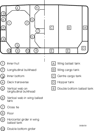
Figure 9.1.4 Structural and spatial terminology
1.6 Information required for CSR Double Hull Oil Tankers
1.6.1 Plans and supporting documents/calculations are to be submitted for approval
in accordance with the requirements of the CSR.
1.6.3 A Ship Construction File (SCF) is to be provided on board of the ship
containing information to facilitate inspection/survey, repair and maintenance. As a
minimum it is to include documentation and plans in accordance with the requirements of
the CSR.
1.6.6 In all cases, as required by the CSR, Pt 1, Ch 13 Ship in Operation -
Renewal Criteria, the mid-ship section plan to be supplied on board the ship is
to include the minimum required hull girder sectional properties. Sectional properties
are to be provided for transverse sections within the cargo length, i.e. each cargo
hold, and are to include:
- sectional properties as defined in CSR, Pt 1, Ch 5, 1 Strength
Characteristics of Hull Girder Transverse Sections;
- the defined section modulus at Deck and at Bottom calculated with
the gross offered thickness;
- the sectional area of the defined Deck and Bottom Zones calculated
with the gross offered thickness; and
- the sectional area of the defined Neutral Axis Zone calculated with
the gross offered thickness minus 0,5 tc.
1.7 Information required for Non-CSR Double Hull Oil Tankers
1.7.1 In addition
to the plans required by Pt 3, Ch 1, 5 Information required,
plans showing the connections for all longitudinals and other framing
members and arrangements at intersections of transverse and longitudinal
framing are also to be submitted.
1.7.2 Any
dry tanks, or tanks for water ballast only, are to be indicated on
the principal structural and arrangement plans.
1.7.4 A docking
plan is to be submitted for consideration of strength requirements
in association with the intended docking condition.
1.7.5 A plan
showing the location of all openings in the deck is to be submitted.
Where it is intended to provide holes in the deck for staging wires,
these holes are also to be shown. Full particulars of the proposed
closing arrangements for all deck openings are to be submitted.
|