
Section
2 Rule structural concepts
2.1 Definition of requirements
2.2 Definition of fore end region
2.2.1 The
fore end region structure is considered to include structure forward
of the midship 0,4L region.
2.3 Definition of aft end region
2.3.1 The
aft end region structure is considered to include all structure aft
of the midship 0,4L region.
2.4 Symbols
2.4.1 The
symbols used in this Section are defined as follows:
|
z
D,
z
B
|
= |
vertical distance, in metres, from the hull
transverse neutral axis to the moulded deck line at side and to the
top of keel respectively |
|
z
ht
|
= |
vertical extent of higher tensile steel. |
2.5 Taper requirements for hull envelope
2.5.1 The
thickness of the shell envelope and strength deck plating, and the
modulus and sectional area of strength deck longitudinals are to taper
gradually from the midship region to the fore and aft ends. For the
requirements, see
Table 3.2.1 Taper requirements for hull
envelope.
2.5.2 Outside
the line of openings where higher tensile steel is used amidships
and mild steel at the ends, the equivalent mild steel midship thickness
for plating, equivalent mild steel midship deck longitudinal area
and equivalent mild steel midship total deck area, for taper purposes
are to be determined as follows:
-
Equivalent mild
steel value
-
If the higher
tensile steel plating is based on minimum thickness requirements,
then:
Equivalent mild steel midship plating thickness determined from Pt 4, Ch 1 General Cargo Ships and Pt 4, Ch 9 Double Hull Oil Tankers.
2.5.3 The
transition from higher tensile steel to mild steel is to be as shown
in Figure 3.2.2 Transition of steel grades for the forward
region. The transition in the aft region is to be similar to the forward
region.
2.5.4 Where
the higher tensile steel longitudinals extend beyond the point of
transition from higher tensile to mild steel plating, the modulus
of the composite section is not to be taken less than the required
mild steel value at the deck plate flange, and k times
the mild steel value at the higher tensile flange.
2.6 Vertical extent of higher tensile steel
2.6.1 Higher
tensile steel may be used for both deck and bottom structures or deck
structure only. Where fitted, it is to be used for the whole of the
longitudinal continuous material for the following vertical distances:
-
from the line
of deck at side
-
from the top of
keel
In the above formulæ F
D and F
B are to be taken not less than k
L.
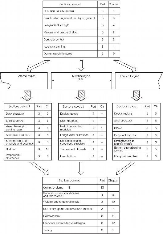
Figure 3.2.1 Rule Scantlings - Schematic layout of requirements
Table 3.2.1 Taper requirements for hull
envelope
| Item
|
Location
|
Requirement
|
| Plating
|
| (1)
|
Shell
envelope plating,
see Notes 1 and 2
|
Fore and aft ends
|
The
thickness, in mm, is to be the greater of the following:(a)
 (see Note 3) (see Note 3)
|
|
|
(b)

|
| (2)
|
Strength deck plating,
see Notes 1 and
2
|
Fore and
aft ends
|
The thickness, in mm, is
to be the greater of the following:
(a)
 (see Note 3) (see Note 3)
|
|
|
(b)

|
| Longitudinals outside 0,4L amidships
|
| (3)
|
Strength
deck,
see Notes 1 and 2
|
Fore and aft
ends
|
MODULUSThe
section modulus in association with deck plating, in cm3, is to
be the greater of the following:
(a)
 (see Note 3)
|
| (b)
As determined by Table 5.2.3 Strength/weather deck
longitudinals forward, Table 6.2.3 Strength/weather deck
longitudinals aft, and Pt 4, Ch 9 Double Hull Oil Tankers, as appropriate
|
| SECTIONAL
AREA
The deck longitudinals may be gradually tapered outside
the 0,4L midships region in association with the deck plating on
the basis of area.
|
|
The sectional area of one longitudinal without plating, in
cm2, is to be not less than the following:
 (see Note 3) (see Note 3)
|
| Strength deck area
|
| (4)
|
Deck area
taper,
see Notes 1 and 2
|
Fore and aft
decks
|
The total area of
longitudinals and deck plating outside line of openings at midship region
should have a linear taper from 0,2L from midships to 0,075L
from F.P. or A.P. such that the area at 0,075L and 0,15L from
the F.P. or A.P. is not less than 30 and 50 per cent respectively of the
total midships area, see Note 3.
|
| Symbols
|
|
L, k, s, T as defined in Pt 3, Ch 5, 1.4 Symbols and definitions 1.4.1
|
|
d
|
= |
distance, in m, from 0,2L forward or aft of
amidships to the mid-length of the building block, strake, or
longitudinal under consideration |
|
|
|
|
s
1
|
= |
s, but is to be taken not less than s
b
|
|
|
t
c
|
= |
actual thickness of deck or shell plating within the
0,4L midships region |
|
|
t
e1
|
= |
basic shell end thickness for taper and is (6,5 +
0,033L) f2)  at 0,075L from the A.P. or F.P. at 0,075L from the A.P. or F.P. |
|
|
t
e2
|
= |
basic strength deck end thickness for taper and is
(5,5 + 0,02L)  at 0,075L from the A.P. or F.P. at 0,075L from the A.P. or F.P. |
|
|
t
t
|
= |
taper thickness for strength deck and shell
plating |
|
|
Z
c
|
= |
section modulus of deck longitudinal in association
with deck plating, in cm3, within the 0,4L
midships region |
|
|
Z
e
|
= |
section modulus of deck longitudinal in association
with deck plating, in cm3, at 0,075L from the
ends |
|
|
Z
t
|
= |
taper section modulus of deck longitudinal in
association with deck plating, in cm3
|
|
|
A
c
|
= |
cross-sectional area of one longitudinal without
attached plating, in cm2, within the 0,4L
midships region |
|
|
A
e
|
= |
cross-sectional area of one longitudinal without
attached plating, in cm2, at 0,075L from the ends |
|
|
A
t
|
= |
taper cross-sectional area of one longitudinal
without attached plating, in cm2
|
|
|
f
2
|
= |
factor to be taken as:
 but need not be taken greater
than 1. L/T is not to be taken greater than 25. but need not be taken greater
than 1. L/T is not to be taken greater than 25.
|
|
|
|
Note
2. The taper requirement does not apply
to container ships or open type ships, see
Pt 3, Ch 4, 2.3 Open type ships, where the requirements of Pt 4, Ch 8, 3.2 Longitudinal strength are applicable, nor to fast cargo
ships where the requirements of Pt 4, Ch 1, 3 Longitudinal strength are applicable. See
also
Pt 3, Ch 4, 5 Hull bending strength for hull section modulus
requirement away from the midship area.
|
|
|
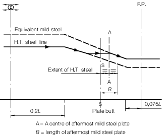
Figure 3.2.2 Transition of steel grades
2.7 Grouped stiffeners
2.7.1 Where
stiffeners are arranged in groups of the same scantling, the section
modulus requirement of each group is to be based on the greater of
the following:
-
the mean value
of the section modulus required for individual stiffeners within the
group,
-
90 per cent of
the maximum section modulus required for individual stiffeners within
the group.
2.8 Rounding policy for plate thickness
2.8.1 Where plating thicknesses as determined by the Rules are required to be rounded, then
this should be carried out to the nearest half millimetre, with thicknesses 0,75 mm
and 0,25 mm being rounded up.
For example,
- for 10,75 ≤ t < 11,25 mm, the Rule required
thickness is 11,0 mm;
- for 11,25 ≤ t < 11,75 mm, the Rule required
thickness is 11,5 mm.
|