
Section
1 General
1.1 Application
1.1.2 The
requirements given are those specific to fore ends and relate to structure
situated in the region forward of 0,3L from the forward
perpendicular.
1.1.3 Requirements
for cargo space structure within this region not dealt with in this
Chapter are to be as detailed in the relevant Chapter of Pt 4 Ship Structures (Ship Types) for the particular ship type.
1.2 Structural configuration
1.2.1 The
Rules provide for both longitudinal and transverse framing systems.
1.2.2 In the
case of container ships and open type ships, additional requirements
may apply as detailed in Pt 4, Ch 8 Container Ships.
1.3 Structural continuity
1.3.1 Suitable
scarfing arrangements are to be made to ensure continuity of strength
and the avoidance of abrupt structural changes.
1.3.2 Where
longitudinal framing terminates and is replaced by a transverse system,
adequate arrangements are to be made to avoid an abrupt changeover.
Where a forecastle is fitted extending aft of 0,15L from
the F.P., longitudinal framing at the upper deck and topsides is generally
to be continued forward of the end bulkhead of this superstructure.
In bulk carriers and oil tankers (see
Pt 3, Ch 5, 1.1 Application 1.1.4) the longitudinal framing
at the upper deck is to be maintained over the cargo space region
and continued over the fore peak region.
1.3.3 In container
or similar ships having continuous side tanks or double skin construction
in way of the cargo spaces, the longitudinal bulkheads are to be continued
as far forward as is practicable and are to be suitably tapered at
their ends. Where, due to the ship's form, such bulkheads are stepped,
suitable scarfing is to be arranged.
1.3.4 In bulk
carriers (see
Pt 3, Ch 5, 1.1 Application 1.1.4)
the topside tank and double bottom hopper tank structures are to be
maintained over the cargo space region, and suitable taper brackets
are to be arranged in line with the end of these tank structures in
the fore peak region. In addition, in way of the cargo space forward
bulkhead, a girder or intercostal bulb plate stiffeners (fitted between
and connected to the bulkhead vertical stiffeners), are to be arranged
on the forward side in line with the sloped bulkheads of the topside
and hopper tanks clear of the taper brackets.
1.4 Symbols and definitions
1.4.1 The
following symbols and definitions are applicable to this Chapter unless
otherwise stated:
|
s
|
= |
spacing
of secondary stiffeners, in mm |
|
t
|
= |
thickness
of plating, in mm |
|
S
|
= |
spacing,
or mean spacing, of primary members, in metres |
|
ρ |
= |
relative density
(specific gravity) of liquid carried in a tank and is to be taken
not less than 1,025. |
1.4.2 For
the purpose of this Chapter the forward perpendicular, F.P., is defined
as the forward limit of the Rule length L.
1.5 Strengthening of bottom forward
1.5.1 The
bottom forward of a sea-going ship is to be additionally strengthened,
except where the ship is so designed that a minimum draught forward, T
FB, of 0,045L can be achieved for
any ballast or part loaded condition. This draught is to be indicated
on the shell expansion plan, the plan showing the internal strengthening,
the Loading Manual and loading instrument, where fitted, see
Pt 3, Ch 4, 8 Loading guidance information.
1.5.2 The
requirements for the additional strengthening apply to ships where L is greater than 65 m. Where a ship is classed for service
in protected waters or extended protected waters, compliance with
the requirements of this Section may be modified or waived altogether.
1.5.3 The
additional strengthening is to extend forward of 0,3L from
the F.P. over the flat of bottom and adjacent plating with attached
stiffeners up to a height of 0,002L above the base line
or 300 mm whichever is the lesser.
1.5.6 Bottom
longitudinals are to pass through and be supported by the webs of
primary members. The vertical web stiffeners are to be connected to
the bottom longitudinals. The cross-sectional area of the connections
is to comply with the requirements given in Table 5.1.1 Additional strengthening of bottom
forward .
1.5.7 The
scantlings required by this Section must in no case be less than those
required by the remaining Sections in Pt 3, Ch 5 Fore End Structure.
1.5.8 For
minimum draught forward, T
FB between 0,01L and
0,045L, the equivalent slamming pressure expressed as
a head of water, h
s, is to be obtained from Figure 5.1.1 Pressure heads, where h
max is calculated from the following expressions:
|
|
65 <
L ≤ 169 m, h
max
|
=
|
 F m
F m
|
|
|
169 <
L ≤ 180 m, h
max
|
=
|
130F m
|
|
|
L > 180 m, h
max
|
=
|
130
Fe–0,0125(L-180)0,705
m
|
where
|
F
|
= |

|
|
|
= |
and |
|
e
|
= |
base
of natural logarithms, 2,7183 |
-
The application
of the maximum pressure for forward of 0,3L from the
F.P. is as indicated in Figure 5.1.1 Pressure heads.
For C
b between 0,70 and 0,80 its position
may be obtained by linear interpolation.
-
Where the bottom
plating forms the boundary of a double bottom tank, deep tank or double
skin tank which is full in all ballast conditions, then for such conditions
the head, h
s, may be reduced by 1,25 times
the head, in metres, of ballast water to top of tank.
-
For bulk carriers
(see
Pt 3, Ch 5, 1.1 Application 1.1.4) the
reduction to the head, h
s, is not to exceed
the head, in metres, of ballast water to the top of the hopper tank
or 1,25 times the depth, in metres, of the double bottom tank, whichever
is the greater.
-
For ballast and
part loaded conditions where the draught forward is less than 0,045L and the reduction to the head, h
s,
has been applied, the ballast tanks are to be filled and a note added
to the loading booklet to this effect, see
Pt 3, Ch 4, 8.2 Loading Manual 8.2.4.(d).
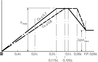
Figure 5.1.1 Pressure heads
1.6 Strengthening against bow flare slamming
1.6.2 The
side structure in the area forward of 0,075L from the
F.P. and above the summer load waterline is to be strengthened against
bow flare impact pressure. The strengthening is to extend vertically
to the uppermost deck level, including the forecastle deck, if fitted,
but need not exceed the level of T + 1,65H
b above
the base line, where H
b is the minimum bow
height, in metres, as derived in Pt 3, Ch 1, 6.1 Principal particulars 6.1.11.
1.6.3 The
flare angle, α, is the angle between the vertical axis and the
tangent of the outer shell measured normal to the shell in a vertical
plane, at the point under consideration. The entry angle, β,
is the angle between the longitudinal axis and the waterplane tangent
measured on the outer shell, at the point under consideration. The
flare angle may normally be derived in accordance with Figure 5.1.2 Flare angle determination.
Table 5.1.1 Additional strengthening of bottom
forward
| Item
|
Requirements
|
| (1)
|
Longitudinally framed bottom shell plating (including keel), see
Notes 1 and 2
|
|
| (2)
|
Bottom
longitudinals - other than flat bars
|
|
| (3)
|
Bottom longitudinals - flat
bars
|
Will be
specially considered
|
|
|
|
Transverse
framing
|
Longitudinal
framing
|
| (4)
|
Primary structure in
way of single bottoms
|
(a) Centre girder:
|
(a) Ships having one or more
longitudinal bulkheads:
|
| Scantlings as required by item (1) in
Table 5.5.1 Single bottom construction
forward, except that in determining
Z in way of a deep tank forward of 0,2L from the F.P. the
value of h5
is to be increased by the following percentages:
|
(i) Centre girder
|
| where TFB
≤ 0,03L
2, 30 per cent
|
Scantlings as required by item (4) in
Table 5.5.1 Single bottom construction
forward and (iii)
|
| where TFB
≥ 0,04L
2, 0 per cent
|
(ii) Bottom transverses
|
| The increase in h5
for intermediate values of TFB
to be obtained by interpolation
|
Maximum spacing
|
| (b) Floors:
|
As for midships region
|
| Scantlings as required by item (2) in
Table 5.5.1 Single bottom construction
forward, except that in way of dry cargo
spaces the minimum face area is to be increased by the following
percentages:
|
Scantlings as required by Pt 4, Ch 9, 9 Primary members supporting longitudinal framing or Pt 4, Ch 10, 2 Primary members supporting longitudinal framing
|
| where TFB
≤ 0,03L
2, 50 per cent
|
(iii) For horizontally stiffened
longitudinal bulkheads and girders the depth to thickness ratio of the panel
attached to the bottom shell plate is not to exceed 
|
| where TFB
≥ 0,04L
2, 0 per cent
|
(iv) Where TFB,
< 0,025L
2the scantlings and arrangements will receive individual
consideration
|
| The increase of minimum face area for
intermediate values of TFB
is to be obtained by interpolation
|
(b) Other ship arrangements will
receive individual consideration
|
| (c) Side girders:
|
|
| Arrangement and scantlings as
required by Pt 3, Ch 5, 5.2 Single bottoms − Transverse framing 5.2.2 and Pt 3, Ch 5, 5.2 Single bottoms − Transverse framing 5.2.3, with the addition of intermediate
half-height girders or equivalent fore and aft stiffening
|
|
| (5)
|
Primary structure in way of double
bottoms, see Note 3
|
(a) Plate floors:
|
(a) Plate floors:
|
|
|
|
Maximum spacing, every frame
|
Maximum spacing:
|
|
|
|
Scantlings as required by Pt 4, Ch 1, 8 Double bottom structure
|
0,002s
F m for TFB
< 0,04L
2
|
|
|
|
(b) Centre and side girders:
|
0,003s
F m for TFB
≥ 0,04L
2
|
|
|
|
Maximum spacing, 0,003S
F m
|
but not to exceed that
required by item (2) in Table 5.5.2 Double bottom construction
forward
|
|
|
|
(c) Intermediate half-height girders
to be arranged midway between side girders:
|
Scantlings as required by
Pt 4, Ch 1, 8 Double bottom structure
|
|
|
|
Scantlings as required for non
watertight side girders by Pt 4, Ch 1, 8 Double bottom structure
|
(b) Centre and side
girders:
|
|
|
|
|
Maximum spacing:
|
|
|
|
|
0,003s
L m for TFB
< 0,04L
2
|
|
|
|
|
0,004s
L m for TFB
> 0,04L
2
|
|
|
|
|
but not to exceed that
required by item (4) in Table 5.5.2
|
|
|
|
|
Scantlings as required by
Pt 4, Ch 1, 8 Double bottom structure
|
| (6)
|
Primary structure in
way of double bottoms supported by longitudinal bulkheads
|
–
|
The scantlings and
arrangements will receive individual consideration on the basis of direct
calculations using, if necessary, a suitably defined two-dimensional
grillage model, see
Pt 3, Ch 1, 3 Equivalents
|
| Symbols
|
L, T, s, k as defined in Pt 3, Ch 5, 1.4 Symbols and definitions 1.4.1
|
c
|
= |
1,0 for S ≤ 2,5 m |
| = |
(0,87 + 0,16S) c
1 for S > 2,5 m |
|
|
c1
|
= |
1,0 for S ≤ 1,0 m |
| = |
(1,14 - 0,14S) for 1,0 m < S ≤ 4,0 m |
| = |
 for S > 4,0 m for S > 4,0 m |
|
|
dw
|
= |
web depth, in mm, which for bulb flats may be taken as
0,9 times the section height |
|
|
f
|
= |

|
| = |
but not greater than 1,0 |
|
|
|
|
|
|
S
|
= |
spacing of primary members, in metres |
|
|
p
|
= |

|
|
|
sF
|
= |
spacing of transverse frames, in mm, for
longitudinally framed side and bottom construction s
F may be taken as sL
|
|
|
sL
|
= |
spacing of bottom longitudinals, in mm |
|
|
tw
|
= |
web thickness, in mm |
|
|
Af
|
= |
cross-sectional area of primary member web stiffener,
in cm2
|
|
|
Afc
|
= |
effective area of primary member web stiffener in way
of butted end connection to the longitudinal, in cm2
|
|
|
AL
|
= |
area of weld of lapped connection, in cm2,
calculated as total length of weld, in cm × throat thickness, in cm |
|
|
Aw
|
= |
area of weld of lug and web connection to the
longitudinal, in cm2, calculated as total length of weld
in cm × throat thickness, in cm |
|
|
A1
|
= |
effective total cross-sectional area of the lug and
web connection to the longitudinal, in cm2
|
|
|
L2
|
= |
L but need not be taken greater than 215 m |
|
|
|
|
α |
= |
Af
 for the web stiffeners for the web stiffeners |
| = |
Afc
 for a butted connection to the longitudinals for a butted connection to the longitudinals |
| = |
AL
 for a lapped connection for a lapped connection |
|
|
|
|
|
Note
1. If intermediate stiffening is fitted
the thickness of the bottom shell plating may be 80 per cent of that
required by (1) but is to be not less than the normal taper
thickness.
|
Note
2. For transverse framing the bottom
shell plating is to be specially considered.
|
Note
3. Particular care is to be taken to
limit the size and number of openings in way of the ends of floors or
girders or to fit suitable reinforcement where such openings are
essential.
|
|
|
1.6.4 The
equivalent bow flare slamming head, h
S, is
to be taken as:
where
|
V
|
= |
as
defined in Pt 3, Ch 5, 1.4 Symbols and definitions 1.4.1
|
|
α |
= |
flare angle,
in degrees, at the point under consideration |
|
β |
= |
entry angle,
in degrees, at the point under consideration |
|
δ |
= |
 and is not to be taken less than zero and is not to be taken less than zero
|
|
e
|
= |
base
of natural logarithms 2,7183 |
|
d
|
= |
vertical
distance, in metres, between the waterline at draught T and
the point under consideration.
|
1.6.5 The
thickness of the side shell is to be not less than:
where
|
sC
|
= |
spacing of secondary stiffeners, in mm, measured along a chord
between parallel adjacent members or equivalent supports, as shown
in Figure 5.1.3 Chord spacing and mean chord spacing for secondary members
|
|
hS
|
= |
bow flare slamming head, in metres, as defined in Pt 3, Ch 5, 1.6 Strengthening against bow flare slamming 1.6.4
|
|
CR
|
= |
panel ratio factor |
|
|
= |
 but is not to be taken less than 0,06 or greater than 0,1 but is not to be taken less than 0,06 or greater than 0,1 |

|
= |
overall panel length,
in metres, measured along a chord between the primary members. |
1.6.6 The
scantlings of secondary stiffeners are not to be less than:
-
Section modulus
of secondary stiffeners
-
Web area of secondary
stiffeners
Table 5.1.2 Permissible stresses
| Item
|
Direct stress, 
|
Shear stress, 
|
|
|
in N/mm2
see Note
|
in
N/mm2
|
| Primary member web stiffener on area
A
f
|
(a) Flat bars
see Note
|
|
—
|
|
|
(b) Bulb plates
see Note
|
|
—
|
|
|
(c) Inverted angles
|
|
—
|
| Primary
member web stiffener on area Afc
|
|
—
|
| Primary
member web stiffener lapped to secondary member on area AL
|
—
|
|
| Lug or web connection
on area A1
|
Single
|
—
|
|
|
|
Double
|
—
|
|
| Symbols
|
Af, AL,
A1 as defined in Table 5.1.1 Additional strengthening of bottom
forward
|
d
|
= |
stiffener depth, in mm |
|
t
|
= |
stiffener web thickness, in mm |
|
Note
 to be taken not greater than to be taken not greater than 
|
1.6.7 The
scantlings of primary members are not to be less than:
-
Section modulus
of primary members
-
Web area of primary
members
1.6.8 For
primary members with cut-outs for the passage of secondary stiffeners,
and which may have web stiffeners connected to the secondary stiffener,
buckling checks are to be carried out to ensure that the primary member
web plating and web stiffener will not buckle under the design load.
The buckling procedure to be followed is given in Table 5.1.3 Buckling procedure for primary
member web plating and web stiffener. Where the web stiffener
is fitted with a bracket, the buckling capability of the web stiffener
in way of the cut-out is to take account of the bracket. Where no
web stiffener is fitted, the buckling capability of the primary member
web plating is to be checked for the total load transmitted to the
connection.
1.6.9 The
structural scantlings required in areas strengthened against bow flare
slamming are to be tapered from 0,075L aft of fore perpendicular
to meet the normal requirements at 0,15L aft of the fore
perpendicular.
1.6.10 Where
the stiffener web is not perpendicular to the plating, tripping brackets
may need to be fitted in order to obtain adequate lateral stability.
1.6.11 For
stiffeners and primary structure, where the angle between the stiffener
web and the plating is less than 70°, the effective section modulus
and shear area are to take account of the non-perpendicularity.
1.6.12 The
side structure scantlings required by this Section must in no case
be taken less than those required by the remaining Sections of Pt 3, Ch 5 Fore End Structure.
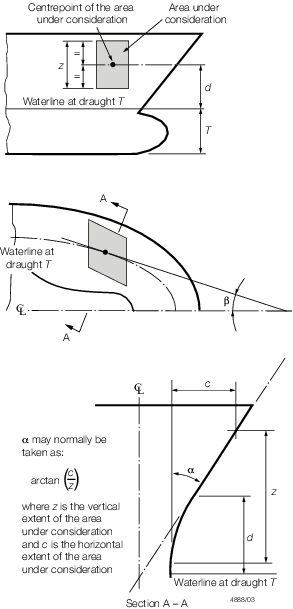
Figure 5.1.2 Flare angle determination
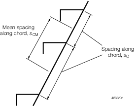
Figure 5.1.3 Chord spacing and mean chord spacing for secondary members
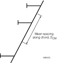
Figure 5.1.4 Mean chord spacing for primary members
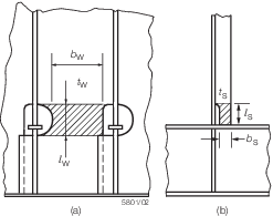
Figure 5.1.5 Dimensions of critical areas of (a) primary member web plating and (b) primary web stiffener
Table 5.1.3 Buckling procedure for primary
member web plating and web stiffener
| Steps
|
Members
|
| Primary member web plating
|
Primary member web stiffener
|
| Determination of the design
compressive stress, σA, N/mm2 (kgf/mm2 )
|
|
|
| Determination of the elastic critical buckling
stress, σE, in compression, N/mm2 (kgf/mm2
)
|
|
|
| Determination of the corrected critical buckling
stress, σCR, in compression, N/mm2 (kgf/mm2
)
|
 where where 
 where where 
|
| Requirement
|
σCR ≥ σA
|
| Symbols
|
bW, bS ,  W, and
  S are dimensions, in mm, as shown in Figure 5.1.5 Dimensions of critical areas of (a) primary member web plating and (b) primary web stiffener S are dimensions, in mm, as shown in Figure 5.1.5 Dimensions of critical areas of (a) primary member web plating and (b) primary web stiffener
|
|
|
|
|
|
tW
|
= |
thickness of primary member web plating, in mm |
|
|
tS
|
= |
thickness of primary member web stiffener, in mm |
|
|
|
|
|
|
E
|
= |
modulus of elasticity, in N/mm2
|
| = |
206000 N/mm2 for steel |
|
|
IW
|
= |

|
|
|
IS
|
= |

|
|
|
P
|
= |
total load transmitted to the connection |
| = |
10,06 SCM sCM hS x
10 –3 kN |
|
|
PW
|
= |
load transmitted through the primary member web
plating, in kN |
| = |
P – P
S, or by direct calculations |
|
|
|
|
σo specified minimum yield stress, in
N/mm2
|
|