
Section
2 Primary members supporting longitudinal framing
2.1 General
2.1.1 These
requirements are applicable to the following structural arrangements
for ships with two longitudinal bulkheads:
-
Centre tank structure:
-
Primary supporting
centreline girder between oiltight transverse bulkheads, in association
with up to five transverses.
-
Bottom transverses
spanning between longitudinal bulkheads in association with a non-primary
centreline docking girder.
-
Double
bottom.
-
Wing tank structure:
-
Transverse
ring structure consisting of bottom, side shell, longitudinal bulkhead
and deck transverses and incorporating one cross-tie or no cross-ties
in tankers not exceeding 75 m in length.
-
Double bottom.
2.1.2 The
requirements are also applicable to structural arrangements incorporating
a single longitudinal bulkhead located on the ship's centreline without
cross-ties, for tankers not exceeding 75 m in length.
2.1.3 The
minimum thickness and constructional detail requirements of Pt 4, Ch 10, 7 Construction details and minimum thickness are to be complied with.
Particular attention is to be paid to the design of end connections
between primary members and buttresses. The shear and combined stress
levels in these connections are to be examined and should be within
the limits specified in ShipRight SDA Procedure - Guidance Notes
on Direct Calculations.
2.2 Symbols
2.2.1 The
symbols used in this Section are defined as follows:
|
b
T
|
= |
overall breadth of tank, in metres |
|
h
c
|
= |
vertical distance from the centre of the cross-tie to deck at
side amidships, in metres |
|
h
s
|
= |
distance between the lower span point of the side transverse
and the moulded deck line at side, in metres |
|
lc
|
= |
one-half
the vertical distance, in metres, between the cross tie and the centre
of the adjacent bottom or deck transverse, or double bottom, see
Figure 10.2.3 Wing tank construction
|
|
lT
|
= |
overall
length of tank, in metres |
|
s
|
= |
spacing of transverses, in metres |
|
A
|
= |
net
sectional area of the web including end bracket where applicable,
in cm2
|
 G G
|
= |
moment
of inertia of the girder, in cm4
|
 T T
|
= |
moment
of inertia of the transverse, in cm4
|
|
Q
x
|
= |
shear force at the actual section under consideration, obtained from
shear force diagrams constructed as indicated, in kN |
|
S
c
|
= |
length of cross-tie between the face plates on the vertical
transverse webs at the cross ties, in metres |
|
S
G
|
= |
span of girder, in metres, and is in no case to be taken less
than (lT − 1,8s) metres
|
|
S
T
|
= |
span of transverses, in metres |
2.3 Structural arrangements
2.3.1 The
spacing of transverses is not to exceed 3,6 m.
2.4 Bottom structure coefficients
2.4.1 Where
a primary supporting bottom centreline girder is fitted, in a single
bottom, the requirements for the girder and transverses may be derived
using bending moment and shear force coefficients K
1 and K
2 determined from Table 10.2.1 Bottom structure
coefficients. To obtain the coefficients, the following factors
are required:
Initially, an estimated value of the ratio  may be used, and an iterative process adopted to obtain
the final required values. may be used, and an iterative process adopted to obtain
the final required values.
2.4.2 Where
bottom transverses are fitted in association with a non-primary centreline
girder the coefficients for the transverse are to be taken as:
For the requirements for the non-primary
girder, see
Pt 4, Ch 10, 2.6 Bottom girders.
2.4.3 In
ships with one longitudinal bulkhead, the coefficient for the bottom
transverse is to be taken as:
-
K
1 = 0,177.
2.5 Bottom transverses
2.5.1 The
section modulus of bottom transverses is to be not less than:
2.5.2 In
ships with two longitudinal bulkheads, the depth of the bottom transverse
web plate is to be not less than 0,2S
T and
the net sectional area of the web at any section, including vertical
end connections, is to be not less than:
where Q
x is calculated from
shear force diagrams constructed as shown in Figure 10.2.1 Bottom transverses. For end connections,
Qx is to be determined by projection of the shear force
diagram as indicated.
2.5.3 The
moment of inertia of bottom transverses is to be not less than:
2.6 Bottom girders
2.6.1 The
section modulus of the primary centreline bottom girder, where fitted,
is to be not less than:
2.6.2 The
net sectional area of the web at any section, including vertical end
connections, is to be not less than:
where Q
x is calculated from
a shear force diagram constructed as shown in Figure 10.2.2 Bottom centreline girder. For end connections, Q
x is to be determined by projection of the shear
force diagram as indicated.
2.6.3 In
a single bottom the section modulus and web area of a non-primary
centreline docking girder are to be not less than:
The scantlings of this girder may, however, be required
to be increased, depending upon the docking condition and support
arrangements, details of which are to be submitted. Consideration
may be required to be given to restricting the level of ballast tank
filling for docking purposes. The loads are to be specially considered
when wing tanks are ballasted for docking.
2.6.4 Consideration
will be given to alternative methods of stiffening in way of the keel
blocks when accompanied by supporting calculations.
2.6.5 In
way of the vertical centreline web and centreline supports to horizontal
girders of transverse bulkheads, the docking girder is to be increased
in depth and scantlings as necessary to provide an effective support.
2.7 Side transverses
2.7.1 The
section modulus of side transverses in ships with one or two longitudinal
bulkheads is to be not less than:
where K
3 is given in Table 10.2.2 Side transverse cofficients.
Table 10.2.1 Bottom structure
coefficients
| (a) 1
GIRDER, 2 TRANSVERSES
|
| β
|
Girder
|
|
K
1
|
K
2
|
| α
|
α
|
| 0,0
|
0,2
|
0,4
|
0,6
|
0,8
|
1,0
|
0,0
|
0,2
|
0,4
|
0,6
|
0,8
|
1,0
|
| 0,02
|
0,210
|
0,210
|
0,195
|
0,175
|
0,125
|
0,0
|
1,000
|
1,000
|
1,000
|
1,000
|
1,000
|
1,000
|
| 0,04
|
0,210
|
0,210
|
0,195
|
0,175
|
0,125
|
0,0
|
0,960
|
0,960
|
0,980
|
1,000
|
1,000
|
1,000
|
| 0,06
|
0,210
|
0,210
|
0,195
|
0,170
|
0,125
|
0,0
|
0,940
|
0,940
|
0,960
|
0,980
|
1,000
|
1,000
|
| 0,08
|
0,205
|
0,205
|
0,190
|
0,167
|
0,125
|
0,0
|
0,920
|
0,920
|
0,940
|
0,970
|
1,000
|
1,000
|
| 0,10
|
0,200
|
0,200
|
0,185
|
0,165
|
0,125
|
0,0
|
0,900
|
0,900
|
0,920
|
0,960
|
0,990
|
1,000
|
| 0,20
|
0,180
|
0,180
|
0,170
|
0,150
|
0,120
|
0,0
|
0,800
|
0,820
|
0,860
|
0,920
|
0,980
|
1,000
|
| 0,40
|
0,150
|
0,150
|
0,150
|
0,135
|
0,115
|
0,0
|
0,670
|
0,730
|
0,760
|
0,840
|
0,950
|
1,000
|
| 0,60
|
0,130
|
0,130
|
0,135
|
0,125
|
0,110
|
0,0
|
0,580
|
0,630
|
0,690
|
0,790
|
0,910
|
1,000
|
| 0,80
|
0,120
|
0,120
|
0,120
|
0,120
|
0,105
|
0,0
|
0,520
|
0,540
|
0,630
|
0,730
|
0,880
|
1,000
|
| 1,00
|
0,100
|
0,100
|
0,115
|
0,115
|
0,100
|
0,0
|
0,460
|
0,500
|
0,580
|
0,680
|
0,850
|
1,000
|
|
|
Transverses
|
| 0,02
|
0,022
|
0,022
|
0,022
|
0,022
|
0,021
|
0,020
|
0,255
|
0,255
|
0,255
|
0,255
|
0,250
|
0,250
|
| 0,04
|
0,023
|
0,023
|
0,023
|
0,022
|
0,021
|
0,020
|
0,263
|
0,263
|
0,257
|
0,255
|
0,250
|
0,250
|
| 0,06
|
0,025
|
0,025
|
0,023
|
0,022
|
0,021
|
0,020
|
0,265
|
0,265
|
0,263
|
0,260
|
0,250
|
0,250
|
| 0,08
|
0,026
|
0,026
|
0,024
|
0,023
|
0,021
|
0,020
|
0.270
|
0,270
|
0,267
|
0,260
|
0,253
|
0,250
|
| 0,10
|
0,027
|
0,027
|
0,025
|
0,023
|
0,022
|
0,020
|
0,275
|
0,275
|
0,270
|
0,263
|
0,255
|
0,250
|
| 0,20
|
0,033
|
0,033
|
0,029
|
0,026
|
0,023
|
0,020
|
0,300
|
0,300
|
0,285
|
0,272
|
0,257
|
0,250
|
| 0,40
|
0,041
|
0,041
|
0,036
|
0,032
|
0,025
|
0,020
|
0,330
|
0,330
|
0,307
|
0,287
|
0,265
|
0,250
|
| 0,60
|
0,047
|
0,047
|
0,041
|
0,036
|
0,026
|
0,020
|
0,355
|
0,355
|
0,325
|
0,302
|
0,273
|
0,250
|
| 0,80
|
0,051
|
0,051
|
0,045
|
0,038
|
0,028
|
0,020
|
0,370
|
0,370
|
0,342
|
0,315
|
0,278
|
0,250
|
| 1,00
|
0,054
|
0,054
|
0,048
|
0,041
|
0,030
|
0,020
|
0,385
|
0,385
|
0,355
|
0,327
|
0,285
|
0,250
|
| (b) 1
GIRDER, 3 TRANSVERSES
|
| β
|
Girder
|
|
K
1
|
K
2
|
| α
|
α
|
| 0,0
|
0,2
|
0,4
|
0,6
|
0,8
|
1,0
|
0,0
|
0,2
|
0,4
|
0,6
|
0,8
|
1,0
|
| 0,02
|
0,290
|
0,290
|
0,290
|
0,270
|
0,200
|
0,120
|
1,400
|
1,400
|
1,500
|
1,500
|
1,500
|
1,500
|
| 0,04
|
0,290
|
0,290
|
0,290
|
0,270
|
0,200
|
0,120
|
1,400
|
1,400
|
1,500
|
1,500
|
1,500
|
1,500
|
| 0,06
|
0,290
|
0,290
|
0,290
|
0,260
|
0,200
|
0,120
|
1,380
|
1,400
|
1,500
|
1,500
|
1,500
|
1,500
|
| 0,08
|
0,280
|
0,280
|
0,280
|
0,250
|
0,195
|
0,115
|
1,340
|
1,370
|
1,470
|
1,470
|
1,480
|
1,500
|
| 0,10
|
0,275
|
0,275
|
0,275
|
0,240
|
0,190
|
0,115
|
1,320
|
1,340
|
1,420
|
1,440
|
1,460
|
1,480
|
| 0,20
|
0,245
|
0,245
|
0,245
|
0,220
|
0,175
|
0,105
|
1,180
|
1,210
|
1,280
|
1,330
|
1,380
|
1,450
|
| 0,40
|
0,200
|
0,200
|
0,200
|
0,185
|
0,160
|
0,090
|
0,970
|
1,030
|
1,080
|
1,200
|
1,280
|
1,420
|
| 0,60
|
0,170
|
0,170
|
0,170
|
0,170
|
0,145
|
0,080
|
0,840
|
0,900
|
0,960
|
1,110
|
1,210
|
1,380
|
| 0,80
|
0,150
|
0,150
|
0,150
|
0,150
|
0,135
|
0,075
|
0,740
|
0,800
|
0,870
|
1,040
|
1,150
|
1,330
|
| 1,00
|
0,135
|
0,135
|
0,135
|
0,135
|
0,125
|
0,070
|
0,680
|
0,740
|
0,810
|
0,960
|
1,100
|
1,300
|
|
|
Transverses
|
| 0,02
|
0,025
|
0,025
|
0,024
|
0,023
|
0,022
|
0,022
|
0,258
|
0,258
|
0,257
|
0,252
|
0,252
|
0,252
|
| 0,04
|
0,026
|
0,026
|
0,025
|
0,024
|
0,023
|
0,023
|
0,267
|
0,267
|
0,267
|
0,262
|
0,262
|
0,260
|
| 0,06
|
0,028
|
0,028
|
0,026
|
0,026
|
0,025
|
0,024
|
0,275
|
0,275
|
0,275
|
0,270
|
0,270
|
0,265
|
| 0,08
|
0,030
|
0,030
|
0,028
|
0,028
|
0,026
|
0,026
|
0,285
|
0,285
|
0,280
|
0,272
|
0,272
|
0,272
|
| 0,10
|
0,032
|
0,032
|
0,029
|
0,029
|
0,028
|
0,027
|
0,292
|
0,292
|
0,287
|
0,277
|
0,275
|
0,275
|
| 0,20
|
0,040
|
0,040
|
0,037
|
0,035
|
0,033
|
0,032
|
0,325
|
0,325
|
0,315
|
0,310
|
0,300
|
0,282
|
| 0,40
|
0,052
|
0,052
|
0,049
|
0,046
|
0,041
|
0,039
|
0,372
|
0,372
|
0,360
|
0,345
|
0,332
|
0,320
|
| 0,60
|
0,059
|
0,059
|
0,057
|
0,054
|
0,048
|
0,045
|
0,405
|
0,405
|
0,392
|
0,375
|
0,357
|
0,342
|
| 0,80
|
0,065
|
0,065
|
0,063
|
0,059
|
0,053
|
0,049
|
0,425
|
0,425
|
0,415
|
0,390
|
0,377
|
0,360
|
| 1,00
|
0,069
|
0,069
|
0,066
|
0,063
|
0,056
|
0,052
|
0,440
|
0,440
|
0,432
|
0,415
|
0,395
|
0,375
|
| (c) 1
GIRDER, 4 TRANSVERSES
|
| β
|
Girder
|
|
K
1
|
K
2
|
| α
|
α
|
| 0,0
|
0,2
|
0,4
|
0,6
|
0,8
|
1,0
|
0,0
|
0,2
|
0,4
|
0,6
|
0,8
|
1,0
|
| 0,02
|
0,370
|
0,350
|
0,330
|
0,315
|
0,275
|
0,215
|
1,890
|
1,890
|
1,920
|
1,940
|
1,960
|
1,990
|
| 0,04
|
0,370
|
0,350
|
0,330
|
0,315
|
0,275
|
0,215
|
1,870
|
1,870
|
1,900
|
1,930
|
1,940
|
1,960
|
| 0,06
|
0,360
|
0,350
|
0,330
|
0,310
|
0,270
|
0,205
|
1,820
|
1,820
|
1,870
|
1,890
|
1,920
|
1,940
|
| 0,08
|
0,350
|
0,340
|
0,320
|
0,300
|
0,260
|
0,200
|
1,760
|
1,800
|
1,820
|
1,840
|
1,880
|
1,920
|
| 0,10
|
0,340
|
0,330
|
0,315
|
0,290
|
0,255
|
0,195
|
1,700
|
1,750
|
1,790
|
1,830
|
1,860
|
1,900
|
| 0,20
|
0,300
|
0,300
|
0,275
|
0,260
|
0,230
|
0,180
|
1,500
|
1,580
|
1,630
|
1,700
|
1,780
|
1,820
|
| 0,40
|
0,240
|
0,240
|
0,230
|
0,220
|
0,200
|
0,155
|
1,240
|
1,300
|
1,400
|
1,540
|
1,620
|
1,700
|
| 0,60
|
0,200
|
0,200
|
0,200
|
0,200
|
0,175
|
0,135
|
1,060
|
1,120
|
1,250
|
1,400
|
1,500
|
1,600
|
| 0,80
|
0,175
|
0,175
|
0,175
|
0,175
|
0,165
|
0,120
|
0,940
|
1,000
|
1,150
|
1,270
|
1,420
|
1,520
|
| 1,00
|
0,150
|
0,150
|
0,150
|
0,150
|
0,150
|
0,105
|
0,850
|
0,920
|
1,050
|
1,200
|
1,340
|
1,460
|
|
|
Transverses
|
| 0,02
|
0,025
|
0,025
|
0,024
|
0,024
|
0,023
|
0,023
|
0,255
|
0,255
|
0,255
|
0,255
|
0,253
|
0,250
|
| 0,04
|
0,027
|
0,026
|
0,026
|
0,025
|
0,025
|
0,024
|
0,272
|
0,270
|
0,268
|
0,266
|
0,260
|
0,255
|
| 0,06
|
0,029
|
0,029
|
0,028
|
0,027
|
0,026
|
0,025
|
0,282
|
0,280
|
0,275
|
0,272
|
0,270
|
0,263
|
| 0,08
|
0,031
|
0,031
|
0,030
|
0,028
|
0,028
|
0,027
|
0,292
|
0,287
|
0,285
|
0,280
|
0,275
|
0,270
|
| 0,10
|
0,033
|
0,033
|
0,032
|
0,030
|
0,029
|
0,028
|
0,300
|
0,295
|
0,290
|
0,285
|
0,280
|
0,275
|
| 0,20
|
0,042
|
0,041
|
0,039
|
0,037
|
0,035
|
0,033
|
0,335
|
0,325
|
0,320
|
0,313
|
0,307
|
0,300
|
| 0,40
|
0,053
|
0,051
|
0,050
|
0,047
|
0,044
|
0,041
|
0,380
|
0,372
|
0,362
|
0,352
|
0,342
|
0,330
|
| 0,60
|
0,061
|
0,059
|
0,057
|
0,054
|
0,050
|
0,047
|
0,412
|
0,405
|
0,387
|
0,376
|
0,365
|
0,355
|
| 0,80
|
0,066
|
0,065
|
0,062
|
0,058
|
0,054
|
0,051
|
0,435
|
0,425
|
0,412
|
0,400
|
0,382
|
0,370
|
| 1,00
|
0,070
|
0,068
|
0,065
|
0,062
|
0,058
|
0,055
|
0,450
|
0,437
|
0,427
|
0,412
|
0,395
|
0,385
|
| (d) 1
GIRDER, 5 TRANSVERSES
|
| β
|
Girder
|
|
K
1
|
K
2
|
| α
|
α
|
| 0,0
|
0,2
|
0,4
|
0,6
|
0,8
|
1,0
|
0,0
|
0,2
|
0,4
|
0,6
|
0,8
|
1,0
|
| 0,02
|
0,455
|
0,440
|
0,410
|
0,380
|
0,345
|
0,300
|
2,330
|
2,350
|
2,370
|
2,400
|
2,420
|
2,450
|
| 0,04
|
0,445
|
0,430
|
0,410
|
0,380
|
0,345
|
0,300
|
2,310
|
2,340
|
2,360
|
2,380
|
2,410
|
2,440
|
| 0,06
|
0,430
|
0,415
|
0,395
|
0,370
|
0,340
|
0,295
|
2,250
|
2,290
|
2,300
|
2,340
|
2,380
|
2,400
|
| 0,08
|
0,415
|
0,400
|
0,385
|
0,365
|
0,330
|
0,290
|
2,180
|
2,230
|
2,280
|
2,290
|
2,340
|
2,360
|
| 0,10
|
0,400
|
0,390
|
0,375
|
0,355
|
0,320
|
0,280
|
2,110
|
2,170
|
2,200
|
2,240
|
2,300
|
2,320
|
| 0,20
|
0,345
|
0,340
|
0,330
|
0,315
|
0,285
|
0,250
|
1,840
|
1,920
|
2,000
|
2,040
|
2,130
|
2,180
|
| 0,40
|
0,270
|
0,265
|
0,265
|
0,265
|
0,235
|
0,200
|
1,500
|
1,600
|
1,700
|
1,790
|
1,900
|
1,970
|
| 0,60
|
0,220
|
0,220
|
0,220
|
0,220
|
0,200
|
0,165
|
1,280
|
1,380
|
1,500
|
1,610
|
1,650
|
1,840
|
| 0,80
|
0,185
|
0,185
|
0,185
|
0,185
|
0,175
|
0,140
|
1,140
|
1,230
|
1,370
|
1,500
|
1,620
|
1,740
|
| 1,00
|
0,165
|
0,165
|
0,165
|
0,165
|
0,160
|
0,125
|
1,040
|
1,140
|
1,280
|
1,420
|
1,540
|
1,650
|
|
|
Transverses
|
| 0,02
|
0,025
|
0,025
|
0,025
|
0,024
|
0,024
|
0,023
|
0,265
|
0,265
|
0,263
|
0,260
|
0,257
|
0,255
|
| 0,04
|
0,028
|
0,028
|
0,028
|
0,027
|
0,026
|
0,025
|
0,280
|
0,280
|
0,275
|
0,270
|
0,267
|
0,265
|
| 0,06
|
0,031
|
0,031
|
0,030
|
0,029
|
0,028
|
0,027
|
0,290
|
0,287
|
0,284
|
0,280
|
0,277
|
0,275
|
| 0,08
|
0,034
|
0,034
|
0,033
|
0,032
|
0,031
|
0,030
|
0,303
|
0,300
|
0,295
|
0,290
|
0,287
|
0,283
|
| 0,10
|
0,037
|
0,036
|
0,036
|
0,034
|
0,033
|
0,032
|
0,312
|
0,309
|
0,305
|
0,300
|
0,297
|
0,292
|
| 0,20
|
0,046
|
0,046
|
0,045
|
0,043
|
0,043
|
0,041
|
0,352
|
0,349
|
0,343
|
0,337
|
0,330
|
0,325
|
| 0,40
|
0,060
|
0,058
|
0,057
|
0,055
|
0,054
|
0,053
|
0,405
|
0,402
|
0,393
|
0,383
|
0,378
|
0,375
|
| 0,60
|
0,068
|
0,067
|
0,065
|
0,064
|
0,063
|
0,061
|
0,435
|
0,432
|
0,426
|
0,417
|
0,412
|
0,407
|
| 0,80
|
0,073
|
0,072
|
0,071
|
0,069
|
0,068
|
0,067
|
0,455
|
0,452
|
0,446
|
0,440
|
0,436
|
0,432
|
| 1,00
|
0,077
|
0,076
|
0,074
|
0,073
|
0,071
|
0,070
|
0,470
|
0,467
|
0,461
|
0,455
|
0,450
|
0,445
|
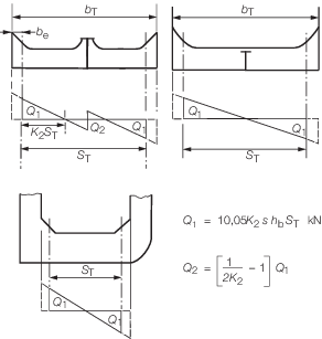
Figure 10.2.1 Bottom transverses
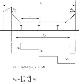
Figure 10.2.2 Bottom centreline girder
2.7.2 In
ships with two longitudinal bulkheads, the net sectional area of the
web at any section is to be not less than:
where Q
x is calculated from
shear force diagrams constructed as shown in Figure 10.2.3 Wing tank construction. For this purpose the
values of K
4 and K
5 and
the range of application is given in Table 10.2.2 Side transverse cofficients.
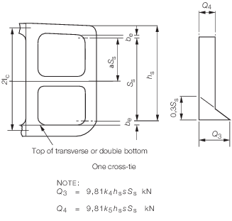
Figure 10.2.3 Wing tank construction
2.7.3 The
moment of inertia of side transverses is to be not less than:
2.8 Deck transverses
2.8.1 The
section modulus of deck transverses is to be not less than:
Where a continuous deck girder is fitted, the term S
T in the above formula is to be replaced by  . .
Table 10.2.2 Side transverse cofficients
2.8.3 The
moment of inertia of the transverses is to be not less than:
2.9 Deck girders
2.9.1 Where
a continuous deck centreline girder supporting deck transverses is
fitted, it is to have a section modulus not less than:
2.9.3 In
way of the vertical centreline web on transverse bulkheads, the continuous
deck girder is to be increased in depth and scantlings as necessary
to provide an effective support.
2.9.4 Where
an intercostal deck girder is fitted, it is to have a depth not less
than 50 per cent of the depth of the deck transverse and the area
of the face flat is to be not less than that of the transverse.
2.9.5 In
way of the vertical centreline web and centreline supports to horizontal
girder on transverse bulkheads, the intercostal deck girder may be
required to be increased in depth and scantlings to provide an effective
support.
2.10 Cross-ties
2.10.1 Cross-ties,
where fitted, may be of plate or sectional material and are to have
an area and least moment of inertia not less than:
2.10.2 Design
of end connections is to be such that the area of the welding, including
vertical brackets, where fitted, is to be not less than the minimum
cross-sectional area of the cross tie derived from Pt 4, Ch 10, 2.10 Cross-ties 2.10.1. To achieve this full penetration
may be required and thickness of brackets may require further consideration.
Attention is to be given to the full continuity of area of the backing
structure on the transverses. Particular attention is also to be paid
to the welding at the toes of all vertical end brackets on the cross-tie.
2.11 Double bottom girders and floors
|