
Section
6 Inner hull, inner bottom and longitudinal oiltight bulkheads
6.1 General
6.1.1 The
inner hull, inner bottom and longitudinal bulkheads are generally
to be longitudinally framed. Longitudinal bulkheads may be plane or
horizontally corrugated. Centreline longitudinal bulkheads may also
be vertically corrugated, see
Pt 4, Ch 9, 1.4 Class notation and applicable Rules for non-CSR Double Hull Oil Tankers 1.4.15. Scantlings of inner hull
and longitudinal oiltight bulkheads are to be in accordance with Table 9.6.1 Inner hull and longitudinal
oiltight bulkhead scantlings and panel stability
is also to be confirmed from primary structure direct calculations.
The calculation is to take account of the shear stress and direct
stresses derived from both the transverse and longitudinal strength
investigations.
Table 9.6.1 Inner hull and longitudinal
oiltight bulkhead scantlings
| Item
|
Horizontally stiffened/Vertically stiffened
|
| (1)
|
Plating thicknesses including
corrugations (mm)
See Notes 1 and 7
|
(a)
|
Within 0,1D of the deck:
t =t
0
|
| (b)
|
Within 0,1D of the bottom shell:
t =  (but not less than t
1) (but not less than t
1)
|
(c)
|
Elsewhere:
t = t
1
see Note 6
|
| (d)
|
But not less
than
t = 0,0009s (0,059L
1+7)
|
| (2)
|
Stiffener modulus
(cm3)
See Notes 3 and 4
|
(a)
|
Horizontally
stiffened:
|
|
|
(i)
|
Z = 0,056kh
2
s
le
2
F
1
|
whichever is the
greater
|
|
|
(ii)
|
Z = 0,0051kh
4
s
le
2
F
2
|
whichever is the
greater
|
(b)
|
Vertically stiffened:
|
|
|
|
Z = 0,0067ks
le
2
h
5
|
| (3)
|
Corrugation
properties
See Note 7
|
(a)
|
Modulus
(cm3):
|
|
|
|
Z = 0,0085ph
5le
2
k
|
| (b)
|
Inertia
(cm4):
|
|
|
|
I = 0,032ph
5le
3
|
Note
2. The section modulus given by the
formula is that of the stiffener and associated plating or of the
corrugation over pitch, p.
Note
3. For vertical stiffeners, the ratio of
web depth to web thickness is not to exceed 60  for stiffeners with flanges or face plates, and 18 for stiffeners with flanges or face plates, and 18  for flat bars. Horizontal stiffeners are to comply
with Pt 4, Ch 9, 5.6 Stability of longitudinals. for flat bars. Horizontal stiffeners are to comply
with Pt 4, Ch 9, 5.6 Stability of longitudinals.
Note
5. The minimum moment of inertia
represented by item 3(b) of the Table is not to be reduced on account
of higher tensile steel being incorporated.
Note
6. In applying item 1(c) of the Table, it
is necessary to calculate values of t
0 for plate panels within 0,4D each side of
mid-depth, take the minimum value, t
m, and then determine value of t
1.
|
6.1.2 Where
tanks are intended to be partially filled, the scantlings and structural
arrangements of the boundary bulkheads are to be capable of withstanding
the loads imposed by the movement of liquid in the tanks. The magnitude
of the predicted loadings, together with the scantling calculations,
may require to be submitted.
6.2 Symbols
6.2.1 The
symbols used in this Section are defined as follows:
|
b
1
|
= |
the greater horizontal distance, in metres, from a point one
third of the height of the strake above its lower edge or mid-point
of the stiffener span, to the corners at the top of the tank on either
side.
Where the angle α is less than  degrees, the distance is measured to the widest point
of the tank, see
Figure 9.6.1 Illustration of b1 determination
. degrees, the distance is measured to the widest point
of the tank, see
Figure 9.6.1 Illustration of b1 determination
.
|
|
c
1
|
= |
 at deck at deck
|
|
|
= |
1,0 at 
|
|
|
= |
 at base line of ship at base line of ship
intermediate values
of c
1 by interpolation
|
|
c
2
|
= |
 at deck at deck
|
|
|
= |
1,0 at 
|
|
|
= |
 at base line of ship at base line of ship
intermediate values
of c
2 by interpolation
|
|
h
|
= |
load
height, in metres measured vertically as follows: |
(a) For bulkhead plating, the distance from a point one third of the height of the plate
panel above its lower edge to the highest point of the tank, excluding hatchway
(b) for bulkhead stiffeners or corrugations, the distance from the mid-point of span of
the stiffener or corrugation to the highest point of the tank, excluding hatchway
|
h
1
|
= |
 , but not less than 0,72 (h + Rb
1) , but not less than 0,72 (h + Rb
1)
|
|
h
2
|
= |
 , in metres, but in no case to be taken less than , in metres, but in no case to be taken less than  m or (0,01L
1 + 0,7) m, whichever
is the greater m or (0,01L
1 + 0,7) m, whichever
is the greater
|
|
h
3
|
= |
distance of longitudinal below deck at side, in metres, but
is not to be less than 0 |
|
h
5
|
= |
h
2 but is to be not less than 0,55h
4
|
|
l
e
|
= |
effective length, in metres, of longitudinals measured between
span points, but is not to be taken less than 2,5 m. For determination
of span points, see
Pt 3, Ch 3, 3 Structural idealisation
|
|
p
|
= |
pitch
of symmetrical corrugations, in mm |
|
t
0
|
= |
0,005s

|
|
t
1
|
= |

|
|
t
m
|
= |
minimum value of t
0 within 0,4D each
side of mid-depth of bulkhead
|
|
D
1
|
= |
D, in metres, but is to be taken not less than
10 and need not be taken greater than 16
|
where θ is the roll angle, in degrees
and 
Other symbols are defined in Pt 4, Ch 9, 1.5 General definitions and symbols.
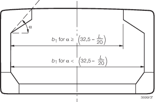
Figure 9.6.1 Illustration of b1 determination
Table 9.6.2 Values of F
1
| Longitudinal bulkhead
longitudinals
|
F
1
|
Above 
|
|
Below 
|
|
|
Note Minimum F
1 = 0,12
|
Table 9.6.3 Values of F
2
| Longitudinal bulkhead
longitudinals
|
F
2
|
Above 
|
|
Below 
|
|
|
Note Minimum F
2 = 0,73
|
6.3 Inner hull and longitudinal bulkheads
6.3.1 Inner
hull and longitudinal bulkheads are to extend as far forward and aft
as practicable and are to be effectively scarfed into the adjoining
structure.
6.3.2 Longitudinal
bulkheads only may be perforated provided suitable account is taken
of the applied shear forces. Proposals to fit perforated longitudinal
bulkheads in cargo tanks will be individually considered. See
also
Pt 4, Ch 9, 7.1 General concerning penetration
of pump-room, cofferdam and cargo tank bulkheads.
6.3.3 The
thickness of inner hull and longitudinal bulkhead plating required
by Table 9.6.1 Inner hull and longitudinal
oiltight bulkhead scantlings is to be maintained
throughout the cargo tank length, with the exception of item (1)(a)
which may be gradually tapered outside 0,4L amidships
to cargo tank minimum thickness or as required by item (1)(c), whichever
is the greater, at 0,075L from the ends.
6.3.4 The
bulkhead plating thicknesses throughout the cargo tank length are
to be increased as necessary to attain compliance with the shear strength
requirements of Pt 3, Ch 4, 6 Hull shear strength.
6.4 Longitudinal corrugated bulkheads
6.4.1 Where
horizontally corrugated bulkheads are adopted the angle of corrugation
is to be not less than 40°.
6.4.2 In ships
exceeding 150 m in length the upper and lower strakes of the longitudinal
bulkhead are to be plane for a distance of 0,1D from
the deck and bottom.
6.4.3 Corrugations
are to be aligned, and stiffening arrangements on plane members are
to be arranged to give adequate support in way of flanges of abutting
corrugations. Where both the longitudinal and transverse bulkheads
are horizontally corrugated, the arrangements at intersections are
to be designed to facilitate attachment and maintain continuity.
6.4.4 Where
asymmetrical girders or webs are fitted to corrugated bulkheads, the
angle of corrugation is not to exceed 60°.
6.5 Inner bottom
6.5.4 Transverse
continuity of inner bottom is to be maintained outboard of inner hull, see
Pt 4, Ch 9, 6.6 Hopper side tank 6.6.3. Recommended
details are shown in the ShipRight FDA Procedure, Structural
Detail Design Guide (SDDG).
6.5.5 Particular attention is to be given to the through thickness properties and
continuity at the connection of bulkhead stools to the inner bottom. For requirements
for plates with specified through thickness properties, see
Ch 3, 8 Plates with specified through thickness properties of the Rules for Materials.
6.6 Hopper side tank
6.6.2 A transverse
is to be arranged in the hopper tank in line with each double bottom
plate floor, to ensure continuity of transverse strength.
6.6.3 Particular
attention is to be paid to the continuity of the inner bottom plating
into the hopper side tank. Scarfing brackets are to be fitted in the
hopper in line with the inner bottom at each transverse. These brackets
are to be arranged each side of the transverse.
6.6.4 Knuckles
in the hopper tank plating are to be supported by side girders and
stringers or by a deep longitudinal.
6.6.5 Detail
design guidelines for connections in way of hopper tank knuckles are
shown in the ShipRight FDA Procedure, Structural Detail Design
Guide (SDDG).
6.7 Connections
6.7.3 Connections
of horizontal stiffeners to transverse bulkheads are to provide adequate
fixity and continuity of longitudinal strength. Horizontal stiffeners
are to be continuous through bulkheads as required by Pt 4, Ch 9, 5.7 Connections of longitudinals, for longitudinals.
6.7.4 Where
inner hulls, longitudinal and transverse bulkheads are horizontally
stiffened, consideration will be given to the stability of the arrangements
at intersections. Additional calculations may be required.
|