
Section
2 Welding
2.1 General
2.1.1 The
plans to be submitted for approval are to indicate clearly details
of the welded connections of main structural members, including the
type and size of welds. This requirement includes welded connections
to steel castings.
The information to be submitted should include the following:
-
Whether weld
sizes given are throat thicknesses or leg lengths.
-
Grades and thicknesses
of materials to be welded.
-
Location, types
of joints and angles of abutting members.
-
Reference to
welding procedures to be used.
-
Sequence of welding
of assemblies and joining up of assemblies.
2.2 Fillet welds
2.2.2 Where
double continuous fillet welding is proposed, the throat thickness
is to be determined taking  equal to 1,0. equal to 1,0.
2.2.3 The
leg length of the weld is to be not less than  times the specified throat thickness. times the specified throat thickness.
2.2.4 The
plate thickness, t
p, to be used in the above
calculation is generally to be that of the thinner of the two parts
being joined. Where the difference in thickness is considerable, the
size of fillet will be considered.
2.2.5 Where
the thickness of the abutting member of the connection (e.g. the web
of a stiffener) is greater than 15 mm and exceeds the thickness of
the table member (e.g. plating), the welding is to be double continuous
and the throat thickness of the weld is to be not less than the greatest
of the following:
-
0,21 x thickness
of the table member. The table member thickness used need not exceed
25mm.
-
0,21 (0,27 in
tanks) x half the thickness of the abutting member.
-
As required by Table 10.2.2 Throat thickness limits.
2.2.6 Except
as permitted by Pt 3, Ch 10, 2.2 Fillet welds 2.2.5, the
throat thickness of the weld is not to be outside the limits specified
in Table 10.2.2 Throat thickness limits.
Table 10.2.1 Weld factors
| Item
|
Weld factor
|
Remarks
|
| (1)
|
General application:
|
|
except as required
below
|
|
|
Watertight plate boundaries
|
0,34
|
|
|
|
Non-tight plate boundaries
|
0,13
|
|
|
|
Longitudinals, frames, beams, and other secondary members to shell, deck or
bulkhead plating
|
0,10
|
|
|
|
|
0,13
|
in
tanks
|
|
|
|
0,21
|
in way of
end connections
|
|
|
Panel stiffeners, etc.
|
0,10
|
|
|
|
Overlap welds generally
|
0,27
|
|
|
|
Longitudinals of the flat-bar type to plating
|
|
see Note 5
|
| (2)
|
Bottom construction in way of holds or
tanks:
|
|
|
|
|
Non-tight
centre girder:
|
to keel
|
0,27
|
|
|
|
|
to inner
bottom
|
0,21
|
no
scallops
|
|
|
|
|
0,21
|
in way of 0,2 × span at
ends
|
|
|
|
|
|
|
|
|
Non-tight boundaries of floors, girders and
brackets
|
0,27
|
in way of
brackets at lower end of main frame
|
|
|
Watertight bottom girders
|
0,34
|
|
|
|
Connection of girder to inner bottom in way of
longitudinal bulkheads supported on inner bottom
|
0,44
|
|
|
|
Inner bottom longitudinals or reverse frames
|
0,13
|
under holds
strengthened for heavy cargoes
|
|
|
|
|
Weld size based on
floor thickness
|
|
|
Connection of floors to inner bottom in way of plane
bulkheads, bulkhead stools, or corrugated and double plate bulkheads
supported on inner bottom. The supporting floors are to be continuously
welded to the inner bottom
|
0,44
|
Weld
material compatible with floor material see Note 4
|
| (3)
|
Hull framing;
|
|
|
|
|
Webs of
web frames and stringers:
|
|
|
|
|
|
to shell
|
0,16
|
|
|
|
|
to face plate
|
0,13
|
|
|
|
Tank side brackets to shell and inner bottom
|
0,34
|
|
| (4)
|
Decks and supporting structure:
|
|
|
|
|
Strength deck plating to shell
|
|
as shown
in Table 10.2.5 Weld connection of strength deck
plating to sheerstrake but alternative proposals will be
considered
|
|
|
Other decks to shell and bulkheads (except where
forming tank boundaries)
|
0,21
|
generally continuous
|
|
|
Webs of cantilevers to deck and to shell in way of
root bracket
|
0,44
|
|
|
|
Webs of cantilevers to face plate
|
0,21
|
|
|
|
Pillars:
|
fabricated
|
0,10
|
|
|
|
|
end
connections
|
0,34
|
see Note 1
|
|
|
|
end connections (tubular)
|
full
penetration
|
|
|
|
Girder web connections and brackets in way of pillar
heads and heels
|
0,21
|
continuous
|
| (5)
|
Bulkheads and tank construction, see also
Pt 4, Ch 7, 10 Bulkheads:
|
|
|
|
|
Plane,
double plate and corrugated watertight bulkhead boundary at bottom, bilge,
inner bottom, deck and connection to shelf plate, where fitted
|
0,44
|
weld size
to be based on thickness of bulkhead plating
|
|
|
|
|
weld
material to be compatible with bulkhead plating material
|
|
|
Shelf plate connection to stool
|
0,44
|
weld size
to be based on thickness of stool at junction with shelf plate. Weld
material to be compatible with stool material
|
|
|
Plane, double plate and corrugated bulkhead boundaries
in way of deep tanks, holds in bulk carriers (see
Pt 3, Ch 10, 1.1 Application 1.1.3) which are floodable for the sea-going
ballast condition or for the carriage of oil cargoes (Holds in bulk carriers
(see
Pt 3, Ch 10, 1.1 Application 1.1.3) which are partially flooded for harbour
conditions will be specially considered):
|
|
|
|
|
- Boundary at bottom, bilge, inner bottom and
deck
|
0,44
|
|
|
|
- Connection of stool and bulkhead to lower stool
shelf plating
|
full
penetration
|
|
|
|
- Connection of stool and bulkhead plating to upper
stool shelf plate
|
0,44
|
|
|
|
- Connection of bulkhead plating to hopper and topside
tanks
|
0,44
|
|
|
|
- Connection of bulkhead plating to side shell
|
0,34
|
|
|
|
Secondary members where acting as pillars
|
0,13
|
|
|
|
Non-watertight pillar bulkhead boundaries
|
0,13
|
|
|
|
Perforated flats and wash bulkhead boundaries
|
0,10
|
|
| (6)
|
Structure in cargo oil tanks of tankers (see
Pt 3, Ch 10, 1.1 Application 1.1.3):
|
|
|
|
|
Bottom longitudinals to shell
|
0,21
|
for
forward of 0,3L
|
|
|
Longitudinal of flat-bar type to plating
|
|
see
Pt 3, Ch 10, 2.2 Fillet welds 2.2.5
|
|
|
Connections between primary structural members
|
0,44
|
at
bottom
|
|
|
|
0,34
|
at
deck
|
|
|
Oiltight bulkhead boundaries:
|
|
|
|
|
|
longitudinal bulkhead
|
0,44
|
see Note 2
|
|
|
|
transverse
bulkhead
|
0,44
|
at
bottom, see Note 3
|
|
|
|
|
0,34
|
at deck,
sides and longitudinal bulkhead
|
|
|
Vertical corrugations to an inner bottom
|
full
penetration
|
|
|
|
Non-tight bulkhead boundaries to plating
|
0,21
|
|
| (7)
|
Structure in cargo tanks of chemical
tankers:
|
|
|
|
|
Tank boundary bulkheads:
|
|
|
|
|
Type 1
ship
|
|
full
penetration
|
|
|
|
Type 2
ship
|
|
|
|
|
|
|
longitudinal bulkheads
|
0,44
|
see Note 2
|
|
|
|
transverse
bulkhead
|
0,44
|
|
|
|
Type 3
ship
|
|
|
|
|
|
|
longitudinal bulkheads
|
0,44
|
see Note 2
|
|
|
|
transverse bulkheads
|
0,44
|
at bottom
see Note 3
|
|
|
|
transverse
bulkheads at deck, sides and longitudinal bulkhead
|
0,34
|
|
| (8) Structure in hoppers of hopper dredgers,
etc.:
|
|
|
|
|
Bulkhead boundary connections
|
0,44
|
at bottom and
bilge
|
|
|
|
|
0,34
|
at deck
and coamings
|
|
|
Cross members to bulkheads and keels
|
0,44
|
|
|
|
Pillar end connections
|
0,34
|
|
|
|
Hopper door hinges
|
full
penetration
|
generally
|
| (9)
|
Structure in machinery space:
|
|
|
|
|
Centre girder to keel and inner bottom
|
0,27
|
|
|
|
Floors to centre girder in way of engine, thrust and
boiler bearers
|
0,27
|
|
|
|
Floors and girders to shell and inner bottom
|
0,21
|
|
|
|
Main engine foundation girders:
|
|
|
|
|
|
to top
plate
|
deep
penetration
|
edge to be prepared
with maximum root 0,33t
p deep penetration generally
|
|
|
|
to hull
structure
|
to depend
on design
|
|
|
|
Floors to main engine foundation girders
|
0,27
|
|
|
|
Brackets, etc. to main engine foundation
girders
|
0,21
|
|
|
|
Transverse and longitudinal framing to shell
|
0,13
|
|
| (10)
|
Construction in 0,25L forward:
|
|
|
|
|
Floors and girders to shell and inner bottom
|
0,21
|
|
|
|
Bottom longitudinals to shell
|
0,13
|
|
|
|
Transverse and longitudinal side framing to
shell
|
0,13
|
|
|
|
Tank side brackets to frame and inner bottom
|
0,34
|
|
|
|
Panting stringers to shell and frames
|
0,34
|
|
|
|
Fore peak construction:
|
|
|
|
|
|
all internal structure
|
0,13
|
unless
a greater weld factor is required
|
| (11)
|
After peak construction:
|
|
|
|
|
All internal structure and stiffeners on after peak
bulkhead
|
0,21
|
unless
a greater weld factor is required
|
| (12)
|
Superstructure and deckhouses:
|
|
|
|
|
Connection of external bulkheads to deck
|
0,34
|
1st and
2nd tier erections elsewhere
|
|
|
|
|
0,21
|
|
|
|
Internal bulkheads
|
0,13
|
|
| (13)
|
Hatchways and closing arrangements:
|
|
|
|
|
Hatchways coamings to deck
|
0,34
|
0,44 at corners
|
|
|
Hatch cover rest bar
|
0,16
|
|
|
|
Hatch coaming stays to coaming
|
0,13
|
|
|
|
Hatch coamings stays to deck
|
0,21
|
|
|
|
Cleats and fittings
|
0,44
|
full penetration
welding may be required
|
|
|
Primary and secondary stiffening of hatch
covers
|
0,10
|
0,13 for tank covers
and where covers strengthened for loads over
|
| (14)
|
Steering control systems:
|
|
|
|
|
Rudder:
|
|
|
|
|
Fabricated mainpiece and mainplace to side plates and
webs
|
0,44
|
|
|
|
Slot welds inside plates
|
0,44
|
|
|
|
Remaining construction
|
0,21
|
|
|
|
Fixed and steering nozzles:
|
|
|
|
|
|
Main
structure
|
0,44
|
|
|
|
|
Elsewhere
|
0,21
|
|
|
|
Fabricated housing and structure of thruster units,
stabilisers, etc.:
|
|
|
|
|
|
Main
structure
|
0,44
|
|
|
|
|
Elsewhere
|
0,21
|
|
| (15) Miscellaneous fittings and equipment:
|
|
|
| Rings for manhole type covers, to deck or
bulkhead
|
0,34
|
|
| Frames of shell and weathertight bulkhead
doors
|
0,34
|
|
| Stiffening of doors
|
0,21
|
|
| Ventilator, air pipe, etc. coamings to deck
|
0,34
|
Load Line Positions 1 and
2
|
|
|
0,21
|
elsewhere
|
| Ventilator, etc. fittings
|
0,21
|
|
| Scuppers and discharges, to deck
|
0,44
|
|
| Masts, derrick posts, crane pedestals, etc. to
deck
|
0,44
|
full penetration welding may be
required
|
| Deck machinery seats to deck
|
0,21
|
generally
|
| Mooring equipment seats
|
0,21
|
generally, but increased or full
penetration welding may be required
|
| Bulwark stays to deck
|
0,21
|
|
| Bulwark attachment to deck
|
0,34
|
|
| Guard rails, stanchions, etc. to deck
|
0,34
|
|
| Bilge keel ground bars to shell
|
0,34
|
Continuous fillet weld, minimum
throat thickness 4 mm
|
| Bilge keels to ground bars
|
0,21
|
Light continuous fillet weld,
minimum throat thickness 3 mm
|
| Fabricated anchors
|
full
penetration
|
|
Note
1. Where pillars are fitted inside tanks
or under watertight flats, the end connection is to be such that the
tensile stress in the weld does not exceed 108 N/mm2.
|
|
|
|
|
Note
4. In way of bulkhead stools in ballast
holds of bulk carriers or in tanks at longitudinal girder/transverse
floor intersection, cut-outs are to be omitted and full penetration
welding is to be applied to both floor and girder for a distance of
150 mm on either side of intersection.
|
Note
5. The throat thickness of the weld is to
be determined by Pt 3, Ch 10, 2.2 Fillet welds 2.2.5. For longitudinals within
D/4 of the strength deck and with a thickness less than 100 mm,
the throat thickness need not exceed 5,5 mm.
|
2.2.7 Double
continuous fillet welding is to be adopted in the following locations,
and may be used elsewhere if desired:
-
Boundaries of
weathertight decks and erections, including hatch coamings, companionways
and other openings.
-
Boundaries of
tanks and watertight compartments.
-
All fillet welds where higher strength steel is used and the global
hull girder stress in way of the fillet weld exceeds 175 N/mm2.
-
All structure in the after peak and the after peak bulkhead stiffeners.
-
All welding inside
tanks intended for chemicals or edible liquid cargoes.
-
All lap welds
in tanks.
-
Primary and secondary
members to bottom shell in the 0,3L forward.
-
Primary and secondary
members to plating in way of end connections, and end brackets to
plating in the case of lap connections.
-
Where Pt 3, Ch 10, 2.2 Fillet welds 2.2.5 applies.
-
All water ballast
tanks.
-
Other connections
or attachments, where considered necessary, and in particular the
attachment of minor fittings to higher tensile steel plating.
2.2.8 Where
intermittent welding is used, the welding is to be made double continuous
in way of brackets, lugs and scallops and at the orthogonal connections
with other members.
2.2.9 As
an alternative to intermittent welding, single sided welding may be
used. Only mechanised single sided welding is acceptable although
manual single sided welding may be used at non-critical locations
e.g. deck house stiffeners. Where single sided welding is used, the
welding is to be made double continuous in way of brackets, lugs and
scallops and at the orthogonal connections with other members.
2.2.10 Where
structural members pass through the boundary of a tank, and leakage
into the adjacent space could be hazardous or undesirable, full penetration
welding is to be adopted for the members for at least 150 mm on each
side of the boundary. Alternatively a small scallop of suitable shape
may be cut in the member close to the boundary outside the compartment,
and carefully welded all round.
2.3 Welding of primary structure
2.3.1 Weld
factors for the connections of primary structure are given in Table 10.2.3 Connections of primary
structure.
Table 10.2.2 Throat thickness limits
| Item
|
Throat thickness, in mm
|
|
|
Minimum
|
Maximum
|
|
(1) Double continuous welding
|
0,21t
p
|
0,44t
p
|
|
(2) Intermittent welding
|
0,27t
p
|
0,44t
p
|
|
|
|
or
4,5
|
|
(3) All welds, overriding minimum:
|
|
|
|
(a) Plate thickness t
p ≤ 7,5 mm
|
|
|
| Hand or automatic
welding
|
3,0
|
—
|
| Automatic deep
penetration welding
|
3,0
|
—
|
|
(b) Plate thickness t
p > 7,5 mm
|
|
|
| Hand or automatic
welding
|
3,25
|
—
|
| Automatic deep
penetration welding
|
3,0
|
—
|
Note
1. In all cases, the limiting value is to
be taken as the greatest of the applicable values given above.
Note
2. Where t
p exceeds 25 mm, the limiting values may be calculated
using a notional thickness equal to 0,4 (t
p + 25) mm.
Note
3. The maximum throat thicknesses shown
are intended only as a design limit for the approval of fillet welded
joints. Any welding in excess of these limits is to be to the
Surveyor's satisfaction.
|
2.3.2 The
weld connection to shell, deck or bulkhead is to take account of the
material lost in the notch where longitudinals or stiffeners pass
through the member. Where the width of notch exceeds 15 per cent of
the stiffener spacing, the weld factor is to be multiplied by:
2.3.3 Where
direct calculation procedures have been adopted, the weld factors
for the 0,2 x overall length at the ends of the members will be considered
in relation to the calculated loads.
2.4 Welding of primary and secondary member end connections
2.4.1 Welding
of end connections of primary members is to be such that the area
of welding is not less than the cross-sectional area of the member,
and the weld factor is to be not less than 0,34 in tanks or 0,27 elsewhere.
2.4.3 The
area of weld, A
w, is to be applied to each
arm of the bracket or lapped connection.
Table 10.2.3 Connections of primary
structure
| Primary member face area, in cm2
|
|
Weld factor
|
| Exceeding
|
Not exceeding
|
Position(1)
|
In tanks
|
In dry spaces
|
|
|
|
|
To
face plate
|
To
plating
|
To face
plate
|
To
plating
|
|
|
30,0
|
At ends
|
0,21
|
0,27
|
0,21
|
0,21
|
|
|
|
Remainder
|
0,10
|
0,16
|
0,10
|
0,13
|
| 30,0
|
65,0
|
At ends
|
0,21
|
0,34
|
0,21
|
0,21
|
|
|
|
Remainder
|
0,13
|
0,27
|
0,13
|
0,16
|
| 65,0
|
95,0
|
At ends
|
0,34
|
0,44(3)
|
0,21
|
0,27
|
|
|
|
Remainder
|
0,27(2)
|
0,34
|
0,16
|
0,21
|
| 95,0
|
130,0
|
At ends
|
0,34
|
0,44(3)
|
0,27
|
0,34
|
|
|
|
Remainder
|
0,27(2)
|
0,34
|
0,21
|
0,27
|
| 130,0
|
|
At ends
|
0,44
|
0,44(3)
|
0,34
|
0,44(3)
|
|
|
|
Remainder
|
0,34
|
0,34
|
0,27
|
0,34
|
Note
1. The weld factors `at ends' are to be
applied for 0,2 x the overall length of the member from each end, but
at least beyond the toes of the member end brackets. On vertical webs
the increased welding may be omitted at the top, but is to extend at
least 0,3 x overall length from the bottom.
|
Note
2. Weld factor 0,34 in cargo oil
tanks.
|
Note
3. Where the web plate thickness is
increased locally, the weld size may be based on the thickness clear
of the increase, but is to be not less than 0,34 x the increased
thickness.
|
Note
4. In tankers over 122 m in length, the
weld factor of the connection of bottom transverses to shell, and of
side transverses to shell and vertical webs to longitudinal and
transverse bulkheads all in the lower half depth, is to be not less
than 0,34.
|
Note
5. The final throat thickness of the weld
fillet to be not less than 0,34t
p in cargo oil tanks.
|
Table 10.2.4 Secondary member end connection
welds
| Connection
|
Weld
area, A
w, in cm2
|
Weld
factor
|
|
(1) Stiffener welded direct to plating
|
0,25A
s or 6,5 cm2
whichever is the greater
|
0,34
|
|
(2) Bracketless connection of stiffeners or stiffener
lapped to bracket or bracket lapped to stiffener:
|
|
|
|
(a) in dry space
|

|
0,27
|
|
(b) in tank
|

|
0,34
|
|
(c) main frame to tank side bracket in 0,15L forward
|
as (a) or (b)
|
0,34
|
|
(3) Bracket welded to face of stiffener and bracket
connection to plating
|
—
|
0,34
|
|
(4) Stiffener to plating for 0,1 x span at ends, or in way
of end bracket if that be greater
|
—
|
0,34
|
| Symbols
|
|
A
s
|
= |
cross sectional area of the stiffener, in
cm2
|
|
A
w
|
= |
the area of the weld, in cm2, and is
calculated as total length of weld, in cm, x throat thickness, in
cm |
|
|
|
Table 10.2.5 Weld connection of strength deck
plating to sheerstrake
| Item
|
Stringer plate thickness, mm
|
Weld
type
|
| 1
|
t ≤ 15
|
Double continuous fillet weld with a
weld factor of 0,44
|
| 2
|
15 < t ≤ 20
|
Single vee preparation to provide
included angle of 50° with root R ≤  t in conjunction with a continuous fillet weld having a weld factor
of 0,39; or
t in conjunction with a continuous fillet weld having a weld factor
of 0,39; or
|
|
|
|
Double vee preparation to provide
included angles of 50° with root R ≤  t
t
|
| 3
|
t > 20
|
Double vee preparation to provided
included angles of 50° with root R ≤  t but not to exceed 10 mm
|
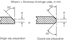
|
Note
1. Welding procedure, including joint
preparation, is to be specified. Procedure is to be qualified and
approved for individual Builders.
Note
3. For thickness t in excess of 20
mm the stringer plate may be bevelled to achieve a reduced thickness
at the weld connection. The length of the bevel is in general to be
based on a taper not exceeding 1 in 3 and the reduced thickness is in
general to be not less than 0,65 times the thickness of stringer plate
or 20 mm, whichever is the greater.
Note
4. Alternative connections will be
considered.
|
2.4.4 Where
a longitudinal strength member is cut at a primary support and the
continuity of strength is provided by brackets, the area of weld is
to be not less than the cross-sectional area of the member.
2.5 Welding equipment
2.6 Welding consumables and equipment
2.7 Welding procedures and welder qualifications
2.7.2 All
welding procedures are to be tested and qualified in accordance with
the requirements of Ch 12 Welding Qualifications of the
Rules for Materials and are to be approved by the Surveyor prior to
construction.
2.7.3 Welders
and welding operators are to be proficient in the type of work to
be undertaken and are to be qualified in accordance with the requirements
specified in Ch 12 Welding Qualifications of the Rules
for Materials.
2.8 Workmanship and shipyard practice
2.8.1 A sufficient
number of skilled supervisors is to be provided to ensure an effective
and systematic control at all stages of welding operations.
2.9 Inspection of welds
2.9.3 In addition to the requirements of Pt 3, Ch 10, 2.9 Inspection of welds 2.9.2, a number of checkpoints are to be examined by
volumetric examination as detailed in Pt 3, Ch 10, 2.9 Inspection of welds 2.9.4 to Pt 3, Ch 10, 2.9 Inspection of welds 2.9.9 and all NDE shall comply with the general NDE
requirements as per Ch 1, 5.1 General NDE requirements of the Rules for the Manufacture, Testing and Certification of Materials, July 2022.
2.9.4 Typical
locations and number of checkpoints to be taken are shown in Table 10.2.6 Checkpoint locations. Critical locations
as identified by ShipRight FDA Procedure (see
Pt 3, Ch 16 ShipRight Procedures for the Design, Construction and Lifetime Care of Ships) are also to be considered.
A plan of the proposed checkpoint locations is to be submitted for
approval.
Table 10.2.6 Checkpoint locations
| Item
|
Location
|
Checkpoints
|
| Intersections of butts and seams of
fabrication and section welds
|
Throughout:
|
|
|
|
(a) hull envelope, shell envelope and
deck structure plating:
|
|
|
|
- at highly stressed areas, see Note 1
|
all
|
|
|
|
1 in 2
|
|
|
(b) longitudinal and
transverse bulkheads
|
1 in 2
|
|
|
(c) inner bottom and
hopper plating:
|
1 in 2
|
| SDA/FDA
|
At critical
locations identified by SDA or FDA, see Note 2
|
all
|
| Butt welds in plating
|
Throughout
|
1 m in 25 m, see Notes 3 and 4
|
| Seam welds in plating
|
Throughout
|
1 m in 100 m
|
| Butt welds in longitudinals
|
Hull envelope within 0,4L
amidships
|
1 in 10 welds, see Note 5
|
|
|
Hull envelope outside 0,4L
amidships
|
1 in 20 welds
|
| Bilge keel butt welds
|
Within 0,4L amidships
|
all
|
|
|
Remainder
|
1 in 3
|
| Structural
items when made with full penetration welding as follows:
|
Throughout
|
|
- connection of stool and bulkhead to lower stool shelf
plating
|
|
1 m in 20
m
|
- vertical corrugations to an inner bottom
|
|
1 m in 20
m
|
|
|
|
1 m in 10
m
|
- sheerstrake to deck stringer
|
|
1 m in 20
m
|
- hatchways coaming to deck
|
|
1 m in 40
m
|
|
|
Hatchway
ends within 0,4L amidships
|
all
|
|
|
Hatchway
ends outside 0,4L amidships
|
1 in
2
|
|
|
Remainder
|
1 in 40
m
|
Note
1. Typically those at sheerstrake, deck
stringer, keel strake and turn of bilge.
|
Note
2. SDA signifies the ShipRight
Structural Design Assessment Procedure, FDA signifies the
ShipRight Fatigue Design Assessment Procedure.
|
Note
3. Checkpoints in butt welds and seam
welds are in addition to those at intersections.
|
Note
4. Welds at inserts used to close
openings in hull envelope plating are to be checked by non-destructive
examination.
|
Note
5. Particular attention is to be given to
repair rates in butt welds in longitudinals. Additional welds are to
be tested if defects such as lack of fusion or incomplete penetration
are observed in more than 10 per cent of the welds examined.
|
2.9.5 Checkpoints
are not to be identified on the ship’s structural components
prior to the welding taking place. Special treatment is not to be
given at these locations except critical locations as identified by ShipRight FDA Procedure.
2.9.6 For
ultrasonic examination the length of each checkpoint is to be 0,5
m and for radiographic examination the length is to be a minimum of
0,3 m. At weld intersections, examination is to be in both weld directions.
2.9.7 The
Builder is to provide the Surveyor with all the NDE reports of the
checkpoints. These reports are to be available for the Surveyor to
review within a short time after inspection, normally considered to
be within 10 working days of the examination being carried out. Where
welds are repaired the NDE report is to include details of examination
of both the defective weld and of the re-weld.
2.9.8 Where
the Surveyor notes that a checkpoint has been repaired without record
of the original defect, the shipyard is to carry out additional examinations
on additional lengths of weld. These lengths are to be adjacent to
and on both sides of the defective checkpoint. These additional examinations
are to be carried out in the presence of the Surveyor and reported
in accordance with Pt 3, Ch 10, 2.9 Inspection of welds 2.9.7.
2.9.9 Where checkpoints are found to contain continuous or semi-continuous
defects, additional lengths of weld adjacent to and on both sides of the defective
length are to be subject to further volumetric examination. For defective welds using
automatic or fully mechanised process, then additional NDE shall be extended to all
areas of the same weld length. The NDE reports are to be submitted in accordance with
Pt 3, Ch 10, 2.9 Inspection of welds 2.9.7.
2.9.10 The following non-destructive examination is to be carried out on ships to
be assigned the class notation ‘ Chemical tanker’:
-
All crossings of butts and seams of cargo tank bulkhead plating
which are welded in assembly areas or on the berth.
-
Where cargo tank boundary welding is completed in assembly areas
or on the berth, a minimum of 10 per cent of the total weld length is to be
crack detected.
-
Where side and bottom longitudinal framing and longitudinal
stiffeners terminate at transverse bulkheads, a minimum of 10 per cent of the
bulkhead boundary connections is to be crack detected in addition to the
requirement given in Pt 3, Ch 10, 2.9 Inspection of welds 2.9.10.(b).
-
Where longitudinal framing and longitudinal bulkhead stiffeners are
continuous through transverse bulkheads, 30 per cent each of the bottom and
shipside boundaries and 20 per cent of the longitudinal bulkhead boundaries are
to be crack detected in addition to the requirement given in Pt 3, Ch 10, 2.9 Inspection of welds 2.9.10.(b).
-
Where transverse framing members are continuous through the cargo
tank boundary, a minimum of 10 per cent of boundary connections is to be crack
detected.
2.9.11 For the items butt and seam welds in plating, shown in Table 10.2.6 Checkpoint locations, consideration may be given for a reduction in
inspection frequency for welds where volumetric inspection and the quality assurance
techniques applied indicate satisfactory quality.
|