
Section
4 Deck structure
4.1 General
4.1.1 Longitudinal
framing is, in general, to be adopted at the strength deck outside
line of openings, but special consideration will be given to proposals
for transverse framing. Requirements are given in this Section for
longitudinal and transverse framing systems of all deck structure,
except decks in way of erections. For erection decks, see
Pt 3, Ch 8 Superstructures, Deckhouses and Bulwarks.
4.2 Deck plating
4.2.3 The
thickness of the strength deck stringer plate is to be increased by
20 per cent at the ends of bridges, poop and forecastle.
4.2.4 The
deck plating thickness and supporting structure are to be suitably
reinforced in way of cranes, masts, derrick posts and deck machinery.
4.2.5 Where
long, wide hatchways are arranged on lower decks, it may be necessary
to increase the deck plating thickness to ensure effective support
for side framing.
4.3 Deck stiffening
4.3.2 The lateral and torsional stability of longitudinals together with web and
flange buckling criteria are to be verified in accordance with Pt 3, Ch 4, 7 Hull buckling strength.
4.3.4 End connection of longitudinals to bulkheads are to provide adequate fixity
and, so far as is practicable, direct continuity of longitudinal strength. Where
L exceeds 215 m, the deck longitudinals are to be continuous through
transverse structure, including bulkheads, but alternative arrangements will be
considered. Higher tensile steel deck longitudinals are to be continuous irrespective of
the ship length.
4.3.6 The end connections of beams are to be in accordance with the requirements
of Pt 3, Ch 10, 3 Secondary member end connections.
Table 1.4.1 Strength/weather deck
plating
| Location
|
Minimum thickness, in mm
|
| Longitudinal
framing
|
Transverse
framing
|
| (1) Outside line of openings (see Notes 1 and 2)
|
The greater
of the following:
|
The greater
of the following:
|
(a) t =
0,001s
1(0,059L
1 + 7)
|
(a) t =
0,001s
1
f
1 (0,083L
1 + 10) 
|
(b) t =
0,00083s
1
 + 2,5 + 2,5
|
(b) t =
0,001s
1
 + 2,5 + 2,5
|
| (2) Inside line of openings
(see Note 2)
|
(b) t =
0,00083s
1
 + 2,5 + 2,5
but not less than 6,5
|
t = 0,00083s
1
 + 1,5 + 1,5
but not less than 6,5
|
| (3) In way of the crown of a
tank
|
or as (1) or (2), whichever is the greater,
but not less than 7,5 mm where L ≥
90m,
or 6,5 mm where L < 90 m
|
| Symbols
|
| L,
k
L,k , ρ, s, S as defined in Pt 4, Ch 1, 1.5 Symbols and definitions 1.5.1
|
f
=  but not to be taken greater than 1,0 but not to be taken greater than 1,0
|
f
1 = 
|
| h
4 = tank head, in metres, as defined in Pt 3, Ch 3, 5 Design loading
|
s
1 = s but is not to be taken less than the smaller of 470
+  mm or 700 mm mm or 700 mm
|
| F
D = as defined in Pt 3, Ch 4, 5.7 Local reduction factors
|
| L
1 = L but need not be taken greater than 190 m.
|
|
|
|
|
Table 1.4.2 Lower deck plating
| Location
|
Minimum thickness, in mm
|
| Second deck
|
Third or platform decks
|
| (1) Outside line of
openings
|
t =
0,012s
1
 but not less than 6,5 but not less than 6,5
|
t =
0,01s
1
 but not less than 6,5 but not less than 6,5
|
| (2) Inside line of openings
|
t = 0,01s
1

but not less than 6,5
|
| (3) In way of the crown or bottom
of a tank
|
|
| but not less than
|
7,5 where L ≥ 90 m,
or
6,5 where L < 90 m
|
| (4) Plating forming the upper
flange of underdeck girders
|
Clear of deck openings, t = 
|
In way of deck openings, t = 1,1 
|
| Minimum breadth, b = 760 mm
|
| Symbols
|
| s, S, k, ρ, as defined in Pt 4, Ch 1, 1.5 Symbols and definitions 1.5.1
|
| b = breadth of increased plating, in mm
|
f = 1,1 –  but not to be taken greater than 1,0 but not to be taken greater than 1,0
|
| h4 = tank head, in metres, as defined in
Pt 3, Ch 3, 5 Design loading
|
s
1 = s but is not to be taken less than the smaller of 470
+  mm or 700 mm mm or 700 mm
|
| A
f = girder face area, in cm2
|
| K
1 = 2,5 mm at bottom of tank
|
| = 3,5 mm at crown of tank
|
|
Note Where a deck loading
exceeds 43,2 kN/m2 (4,4 tonne-f/m2), the thickness
of plating will be specially considered.
|
Table 1.4.3 Strength/weather deck
longitudinals
| Location
|
Modulus, in cm3
|
Inertia, in cm4
|
| (1) In way of dry cargo
spaces, see Note 1
|
|
|
| (a) Outside line of
openings
|
Z = 0,043 s k h
T1
 e
2
F
1
e
2
F
1
|
—
|
| (b) Inside line of
openings
|
Z = s k(400h
1 + 0,005 ( e
L
2)2) × 10–4
e
L
2)2) × 10–4
|
—
|
| (2) In way of the
crown or bottom of a tank
|
|
|
| or as (1)(a) or (1)(b)
above, whichever is the greater
|
| (3) In way of
superstructure
|
To be specially considered
|
—
|
| Symbols
|
| L, s,
kL, k, ρ as defined in Pt 4, Ch 1, 1.5 Symbols and definitions 1.5.1
|
| b = 1,4 for
rolled or built sections
= 1,6 for flat bars
|
c1= 
|
| dw= depth of longitudinal, in mm
|
| F1
= 0,25c
1
|
| h1
= weather head, in metres, as defined in Pt 3, Ch 3, 5 Design loading
|
| h4
= tank head, in metres, as defined in Pt 3, Ch 3, 5 Design loading
|
| le
= as defined in Pt 4, Ch 1, 1.5 Symbols and definitions 1.5.1, but not to be taken less than 1,5 m
|
| F
D = as defined in Pt 3, Ch 4, 5.7 Local reduction factors
|
hT1 =  for Type `B-60' ships for Type `B-60' ships
= the greater of  or 1,20 m for Type `B' ships or 1,20 m for Type `B' ships
|
| L1
= L but need not be taken greater than 190 m
|
| L2 = L but need not be taken greater than 215
m
|
|
|
Note
2. The buckling requirements of Pt 3, Ch 4, 7 Hull buckling strength are to be complied with.
The ratio of the web depth d
w to web thickness t is to comply with the following
requirements:
(a) Built up profiles and rolled angles:

(b) Flat bars:

when continuous at bulkheads
 when non-continuous at bulkheads when non-continuous at bulkheads
|
Note
3. The web depth of longitudinals,
dw is to be not less than 60 mm.
|
Table 1.4.4 Cargo and accommodation deck
longitudinals
| Location
|
Modulus, in
cm3
|
Inertia, in
cm4
|
| (1) Cargo decks
|
|
|
| (a) L ≥ 90 m
|
Z = sk(5,9L
1 + 25h
2
 e
2) × 10–4
e
2) × 10–4
|
—
|
| (b) L < 90 m
|
Z = 0,005s k h
2
 e
2
e
2
|
—
|
| (2) Accommodation decks
|
|
|
| (a) L ≥ 90 m
|
Z = sk(5,1L
1 + 25h
3
l
e
2) × 10–4
|
—
|
| (b) L < 90 m
|
Z = 0,00425s k h
3
l
e
2
See Note 1
|
—
|
| (3) In way of the crown
or bottom of a tank
|
As in (1) or (2) as
applicable, or
whichever is the greater
|
|
| Symbols
|
| L, s, k, ρ as defined in Pt 4, Ch 1, 1.5 Symbols and definitions 1.5.1
|
| dw = web depth of longitudinal, in mm,
see Note 2
|
| h2 = cargo head, in metres, as defined in
Pt 3, Ch 3, 5 Design loading
|
| h3 = accommodation head, in metres, as
defined in Pt 3, Ch 3, 5 Design loading
|
| h4 = tank head, in metres, as defined in
Pt 3, Ch 3, 5 Design loading
|
| le = as defined in Pt 4, Ch 1, 1.5 Symbols and definitions 1.5.1, but not to be taken less than 1,5
m
|
| L1 = L but need not be taken greater
than 190 m
|
| γ = 1,4 for rolled or built sections
= 1,6
for flat bars
|
|
|
Note
2. The web depth of longitudinals,
d
w, to be not less than 60 mm.
|
Table 1.4.5 Strength/weather, cargo and
accommodation deck beams
| Location
|
Modulus, in
cm3
|
Inertia, in
cm4
|
| (1) Strength/weather decks
|
The lesser of the
following:
(a) Z = (K
1
K
2
TD + K
3
B
1
s h
1
 e
2) k × 10–4
e
2) k × 10–4
(b) Z = 2K
3
B
1
s k h
1
 e
2 × 10⁻⁴
e
2 × 10⁻⁴
|
—
|
| (2) Cargo decks
|
Z = (400K
1
TD + 38,8s
h
2
 e
2) k × 10–4
e
2) k × 10–4
|
—
|
| (3) Accommodation decks
|
Z = (530K
1
TD + 38,8s
h
3
 e
2) k × 10–4
e
2) k × 10–4
|
—
|
|
(4) In way of the crown or bottom of a tank
|
As (1), (2) or (3) as applicable,
or
whichever is the greater
|
|
| Symbols
|
| B, D, T, s, k, ρ as defined in Pt 4, Ch 1, 1.5 Symbols and definitions 1.5.1
|
| dw = depth of beam, in mm
|
| h1 = weather deck head in metres, see
Pt 3, Ch 3, 5 Design loading
|
| h2 = cargo head in metres, see
Pt 3, Ch 3, 5 Design loading
|
| h3 = accommodation head in metres, see
Pt 3, Ch 3, 5 Design loading
|
| h4 = tank head in metres, see
Pt 3, Ch 3, 5 Design loading
|
|
l
e as defined in Pt 4, Ch 1, 1.5 Symbols and definitions 1.5.1, but to be taken as not less than 1,83 m
|
| B
1 = B, but need not be taken greater than 21,5 m
|
K1 = a factor dependent on the number of decks
(including poop and bridge superstructures) at the position of the beam
under consideration:
|
|
= |
1 deck 20,0 |
| = |
2 decks 13,3 |
| = |
3 decks 10,5 |
| = |
4 or more 9,3 |
|
K2 = a factor dependent on the location of the
beam:
|
|
= |
at short bridge and poops 133 |
| = |
elsewhere 530 |
|
K3 = a factor dependent on the location of the
beam:
|
|
= |
elsewhere 3,3 |
| = |
span adjacent to the ship side 3,6 |
|
| γ = 1,4
for rolled or built sections
|
Note
1. Where weather decks are intended to
carry deck cargo and the load is in excess of 8,5 kN/m2,
the scantlings of beams may be required to be increased to comply with
the requirements for location (2) using the equivalent design head,
for specified cargo loading, for weather decks given in Table 3.5.1 Design heads and permissible cargo
loadings.
Note
2. The web depth of beams, d
w, is to be not less than 60 mm.
|
4.4 Deck supporting structure
4.4.1
Girders
and transverses supporting deck longitudinals and beams, also
hatch side girders and hatch end beams, are to comply with the requirements
of Table 1.4.6 Deck girders, transverses and
hatch beams. In general,
transverses, webs or frames of increased scantlings, see
Table 1.6.3 Shell framing (transverse), are to be arranged
in way of hatch end beams and deck transverses, and these are to be
in line with the double bottom floors where practicable. Equivalent
transverse ring scantling arrangements will be considered.
4.4.2
Transverses supporting deck longitudinals are, in general, to be spaced
not more than 3,8 m apart where the length, L, is 100
m or less, and (0,006L + 3,2) m apart where L is
greater than 100 m.
4.4.4 Where
a girder is subject to concentrated loads, such as pillars out of
line, the scantlings are to be suitably increased. Also, where concentrations
of loading on one side of the girder may occur, the girder is to be
adequately stiffened against torsion. Reinforcements may be required
in way of localised areas of high stress.
4.4.6 Pillars
are to be fitted in the same vertical line wherever possible, and
effective arrangements are to be made to distribute the load at the
heads and heels of all pillars. Where pillars support eccentric loads,
they are to be strengthened for the additional bending moment imposed
upon them.
4.4.7 Tubular
and hollow square pillars are to be attached at their heads to plates
supported by efficient brackets, in order to transmit the load effectively.
Doubling or insert plates are to be fitted to the inner bottom under
the heels of tubular or hollow square pillars, and to decks under
large pillars. The pillars are to have a bearing fit and are to be
attached to the head and heel plates by continuous welding. At the
heads and heels of pillars built of rolled sections, the load is to
be well distributed by means of longitudinal and transverse brackets.
4.4.8 In double
bottoms under widely spaced pillars, the connections of the floors
to the girders, and of the floors and girders to the inner bottom,
are to be suitably increased. Where pillars are not directly above
the intersection of plate floors and girders, partial floors and intercostals
are to be fitted as necessary to support the pillars. Manholes are
not to be cut in the floors and girders below the heels of pillars.
Where longitudinal framing is adopted in the double bottom, equivalent
stiffening under the heels of pillars is to be provided, and where
the heels of pillars are carried on a tunnel, suitable arrangements
are to be made to support the load.
4.4.9 Where pillars are fitted inside tanks or under watertight flats, the
tensile stress in the pillar and its end connections is not to exceed 108
N/mm2 at the test heads. In general, such pillars should be of built
sections, and end brackets may be required.
4.4.10 Pillars
are to be fitted below deckhouses, windlasses, winches, capstans and
elsewhere where considered necessary.
4.5 Deck openings
4.5.1 The corners of main cargo hatchways in the strength deck within 0,5L
amidships are to be elliptical, parabolic or rounded, with a radius generally not less
than  of the breadth of the opening. Rounded corners are to have a minimum
radius of 300 mm if the deck plating extends inside the coaming, or 150 mm if the
coamings are welded to the inner edge of the plating in the form of a spigot. Where
elliptical corners are arranged, the major axis is to be fore and aft, the ratio of the
major to minor axis is to be not less than 2 to 1 nor greater than 2,5 to 1, and the
minimum half-length of the major axis is to be defined by l
1 in Figure 1.4.5 Elliptical and parabolic
corners. Where parabolic corners are arranged, the
dimensions are also to be as shown in Figure 1.4.5 Elliptical and parabolic
corners. of the breadth of the opening. Rounded corners are to have a minimum
radius of 300 mm if the deck plating extends inside the coaming, or 150 mm if the
coamings are welded to the inner edge of the plating in the form of a spigot. Where
elliptical corners are arranged, the major axis is to be fore and aft, the ratio of the
major to minor axis is to be not less than 2 to 1 nor greater than 2,5 to 1, and the
minimum half-length of the major axis is to be defined by l
1 in Figure 1.4.5 Elliptical and parabolic
corners. Where parabolic corners are arranged, the
dimensions are also to be as shown in Figure 1.4.5 Elliptical and parabolic
corners.
4.5.2 Where the corners of large openings in the strength deck are parabolic or
elliptical, insert plates are not required. For other shapes of corner, insert plates of
the size and extent shown in Figure 1.4.6 Insert plates for large
openings will, in general, be required. The required
thickness of the insert plate is to be not less than 25 per cent greater than the
adjacent deck thickness, outside line of openings with a minimum increase of 4 mm. The
increase need not exceed 7 mm.
4.5.3 Welded attachments close to or on the free edge of the hatch corner plating
are to be avoided (e.g. welded protection strips or shedder plates) and the butt welds
of corner insert plates to the adjacent deck plating are to be located well clear of
butts in the hatch coaming.
4.5.4 Openings in the strength deck outside the line of hatch openings are to be
kept to the minimum number consistent with operational requirements. Openings are to be
arranged clear of hatch corners and, so far as possible, clear of one another. Where,
within 0,4L amidships, deck openings have a total breadth or shadow area breadth,
in one transverse section that exceeds the limitation given in Pt 3, Ch 3, 3.4 Calculation of hull section modulus 3.4.6 and Pt 3, Ch 3, 3.4 Calculation of hull section modulus 3.4.7, compensation will be required to restore the
excess. This is generally to be arranged by increasing the deck plate thickness, but
other proposals will be considered. Plate panels in which openings are cut are to be
adequately stiffened, where necessary, against compression and shear buckling. The
corners of all openings are to be well rounded and the edges smooth.
Table 1.4.6 Deck girders, transverses and
hatch beams
| Location and
arrangements
|
Modulus, in
cm3
|
Inertia, in cm4
|
|
(1) Girders and transverses in way of dry cargo spaces and
clear of hatch openings:
|
See
also Note
|
|
|
(a) supporting up to three point loads
|
Z to be determined from calculations using Note and stress  N/mm2 N/mm2
 and assuming fixed ends. and assuming fixed ends.
|
|
|
(b) supporting four or more point loads or a uniformly
distributed load
|
Z = 4,75k S Hg
 e
2
e
2
|
|
|
(2) Hatch side girders in way of dry cargo spaces at weather
decks (with deep coamings):
|
|
|
|
(a) supporting up to three point loads
|
Z to be determined from calculations using Note and stress  N/mm2 N/mm2
 and assuming fixed ends and assuming fixed ends
|
|
|
(b) supporting four or more point loads or a uniformly
distributed load
|
Z = 5,85kS1Hgle
2
|
|
|
(3) Hatch side girders in way of dry cargo spaces at lower
decks (without deep coamings):
|
|
|
|
(a) supporting up to three point loads
|
Z to be determined from
calculations using stress N/mm2 N/mm2

|
|
|
(b) supporting four or more point loads or a uniformly
distributed load
|
Z = 5,20kS1Hgle
2
|
|
|
(4) Hatch end beams in way of dry cargo spaces and supported
at centreline, see
Figure 1.4.1 Hatch end beam
arrangements:
|
|
|
|
(a) In association with longitudinal framing when there is
no transverse between the hatch end beam and adjacent transverse bulkhead
or equivalent supporting structure
|
Z = 19k K
1
H
g
l
e
S
1
l
1 + 2,37k
S
e
H
g
l
e
2
|
|
|
(b) In association with longitudinal framing where there is
one or more transverse between the hatch end beam and adjacent transverse
bulkhead or equivalent supporting structure
|
Z = 19k K
1
H
g
l
e(S
1
l
1 + S
2
l
2)
|
|
|
(c) In association with transverse framing when the hatch
end beam supports the hatch side girder and in line girder only
|
Z = 19k K
1
H
g
l
e(S
1
l
1 + S
3
l
3)
|
|
|
(d) In association with transverse framing when the hatch end
beam supports the hatch side girder, an in line girder and an additional
girder between the hatch side and the centreline
|
Z = 19k
H
g
l
e(K
1(S
1
l
1 + S
4
l
4) + K
2
S
5
l
5)
|
|
|
(5) Girders and transverses in way of the crown or bottom of
a tank
|
Z = 11,7ρ
k h
4
S l
e
2
|
|
| Symbols
|
S,  e, k, ρ as defined in Pt 4, Ch 1, 1.5 Symbols and definitions 1.5.1
|
K
1, K
2 = factors, dependent on the girder arrangments, as
follows:
|
| h
4 = tank head, in metres, as defined in Pt 3, Ch 3, 5 Design loading
|
 or or 
|
K
1 or K
2
|
|
 1,
1,  2,
2,  3,
3,  4,
4,  5 , in metres, as indicated in Figure 1.4.1 Hatch end beam
arrangements
5 , in metres, as indicated in Figure 1.4.1 Hatch end beam
arrangements
Bh = breadth of hatchway, in metres, as
used to determine K
1
H
g = weather head h
1, or cargo head h
2, or accommodation head h
3, in metres, as defined in Pt 3, Ch 3, 5 Design loading, whichever is applicable
|
- 0,2
- 0,3
- 0,4
- 0,5
- 0,6
- 0,7
- 0,8
- 0,9
- 1,0
|
- 0,143
- 0,177
- 0,191
- 0,187
- 0,179
- 0,169
- 0,141
- 0,085
- 0,000
|
|
|
S
e, S
1, S
2, S
3, S
4, S
5, in metres as indicated in Figure 1.4.1 Hatch end beam
arrangements
X = distance, in metres, from centreline of ship to
an additional girder, if fitted, as shown in Figure 1.4.1 Hatch end beam
arrangements, as used to determine K
2
|
Note In single deck ships the section modulus of deck
transverses is to be increased by 15 per cent.
|
Table 1.4.7 Pillars
| Symbols
|
Parameter
|
Requirement
|
| b = breadth of
side of a hollow rectangular pillar or breadth of flange or web of a built
or rolled section, in mm
dp = mean diameter
of tubular pillars, in mm
|
(1) Cross-sectional area of all types of pillar
|
See Note
|
| k = local scantling higher tensile steel factor,
see
Pt 3, Ch 2, 1.2 Steel 1.2.3, but not less than 0,72
 = overall length of pillar, in metres = overall length of pillar, in metres
 = effective length of pillar, in metres, and is taken
as: = effective length of pillar, in metres, and is taken
as:
for hold pillars 0,65
for 'tween deck pillars 0,80
 p = distance, in metres, between centres of
two adjacent spans of girders or transverses supported by the
pillar. p = distance, in metres, between centres of
two adjacent spans of girders or transverses supported by the
pillar.
|
(2) Minimum wall thickness of tubular pillars
|
The greater of the following:
(a) 
(b) 
but not to be less than
(c) t = 5,5 mm where L < 90 m, or
= 7,5 mm where L ≥ 90 m
|
| r = least radius of gyration of pillar
cross-section, in mm, and may be taken as:
Ap = cross-sectional area of
pillar, in cm2
C, S as defined in Pt 4, Ch 1, 1.5 Symbols and definitions 1.5.1
H
g as defined in Table 1.4.6 Deck girders, transverses and
hatch beams
 = least moment of inertia of cross-section, in
cm4 = least moment of inertia of cross-section, in
cm4
|
(3) Minimum wall thickness of hollow rectangular pillars or
web plate thickness of  or channel sections or channel sections
|
The lesser of (b) and (c) and not to be less than (a):
(a) 
(b) 
(c) 
but to be not less than
t = 5,5 mm where L < 90 m, or
= 7,5 mm where L ≥ 90 m
|
| P = load, in kN, supported by the pillar and is to
be taken as
but not less than 19,62 kN
|
(4) Minimum thickness of flanges of angle or channel
sections
|
The lesser of the following:
(a) 
(b) 
|
| Pa = load, in kN, from pillar or pillars
above (zero if no pillars over)
|
(5) Minimum thickness of flanges of built or rolled  sections sections
|
The lesser of the following:
(a) 
(b) 
|
Note As a first approximation A
p may be taken as  and the radius of gyration estimated for a suitable
section having this area. and the radius of gyration estimated for a suitable
section having this area.
|
Note If the area calculated using this radius of gyration
differs by more than 10 per cent from the first approximation, a
further calculation using the radius of gyration corresponding to the
mean area of the first and second approximation is to be made.
|
4.5.5 Openings in the strength deck outside the line of hatch openings having a
stress concentration factor in excess of 2,4 will require edge reinforcements in the
form of a spigot of adequate dimensions, but alternative arrangements will be
considered. The area of any edge reinforcement which may be required is not to be taken
into account in determining the required sectional area of compensation for the opening.
Alternatively, the shape of the opening is to be such that a stress concentration factor
of 2,4 is not exceeded. In this respect, reinforcement will not in general, be required
in way of:
-
elliptical openings having their major axis fore and aft and a ratio
of length to breadth not less than 2 to 1, or
-
openings of other shapes provided that it has been shown by suitable
tests that the stress concentration factor does not exceed 2,4.
Table 1.4.8 Non-watertight pillar
bulkheads
| Parameter
|
Requirement
|
| Ships with L < 90 m
|
Ships with L ≥ 90 m
|
| (1) Minimum thickness of
bulkhead plating
|
5,5 mm in holds and
'tween decks
|
7,5 mm in holds
|
| 6,5 mm in 'tween decks
|
| (2) Maximum stiffener spacing
|
1500 mm
|
1500 mm
|
| (3) Minimum depth of
stiffeners or corrugations
|
100 mm in holds
|
150 mm in holds
|
| 75 mm in 'tween decks
|
100 mm in 'tween decks
|
| (4) Cross-sectional area (including
plating) for rolled, built or swedged stiffeners supporting beams,
longitudinals, girders or transverses
|
(a) Where
(b) Where
(c) Where 
|
A = A
1
A = A
2
A is obtained by interpolation
between A
1 and A
2
|
| (5) Cross-sectional area (including
plating) for symmetrical corrugation
|
(a) Where

(b) Where

|
A = A
1
A = A
2
|
| Symbols
|
| d
w, t
p, b, c as defined in Pt 3, Ch 3, 3 Structural idealisation
|
r =
radius of gyration, in mm, of stiffener and attached plating
|
|
= |
 mm for rolled, built or swedged stiffeners mm for rolled, built or swedged stiffeners |
| = |
 mm for symmetrical corrugation mm for symmetrical corrugation |
|
 = moment of inertia, in cm4, of stiffener and
attached plating = moment of inertia, in cm4, of stiffener and
attached plating
|
| s =
spacing of stiffeners, in mm
|
| A =
cross-sectional area, in cm2, of stiffener and attached plating
|
A1 = 
|
| As a first
approximation A
1 may be taken as
|

|
A2 = 
|
| As a first
approximation A
2 may be taken as
|

|
| P, l
e as defined in Table 1.4.7 Pillars
|

|
4.5.6 Lower deck openings should be kept clear of main hatch corners and the areas
of high stress, so far as possible. Compensation will not, in general, be required
unless the total width of openings in any frame space, or between any two transverses,
exceeds 15k per cent of the original effective plating width. The requirements of
Pt 4, Ch 1, 4.5 Deck openings 4.5.4 also apply to lower deck openings except that:
-
the thickness of inserts, if required, for the second deck hatch
corners is to be 2,5 mm greater than the deck thickness,
-
inserts will not generally be required for hatch corners on third
decks, platform decks and below, and
-
reinforcement will not generally be required for circular openings,
provided that the plate panels in which they are situated are otherwise adequately
stiffened against compression and shear buckling.
4.5.7 All openings are to be adequately framed; attention is to be paid to
structural continuity, and abrupt changes of shape, section or plate thickness are to be
avoided. Arrangements in way of corners and openings are to be such as to minimise the
creation of stress concentrations. Where a deck longitudinal is cut, compensation is to
be arranged to ensure full continuity of strength.
Table 1.4.9 Cantilever beams
| Location and
supporting arrangements
|
Required modulus, in cm3, see Notes
|
| Cantilever
beam
|
Supporting frame
|
| (1) Any position - no support
from end girders
|
Zо
= 8,67k
M
о(Z
о = 85k
M
о)
|
Z
v = 
|
| (2) At hatch side - uniform loading,
partial support received from hatch side girder, see
Figure 1.4.3 Section moduli of hatch end beams :
|
|
Z
v = 
|
| (a) Hatch side girder supported by
Rule hatch end beams or pillars at hatch corners
|
Z
u = 
|
| (b) Hatch side girder supported by end
bulkheads of hold - no Rule hatch end beams or pillars
|
Z
u as in (a) or the following formula, whichever is the
greater:
|
| (c) No transverse bulkheads between
hatchways, no Rule hatch end beams or pillars, see Notes
|
Z
u as in (a) or the following formula, whichever is the
greater:
|
| (d) At hatch side - concentrated
loading
|
Z
u as in (a), (b) or (c), whichever is applicable, or as the
following formula, whichever is the greater:
|
|
|
Required inertia, in cm4
|
| Case (1) or (2)
|
|
—
|
Note
1. Where a transverse bulkhead is fitted
at only one end of a hatchway the section modulus of cantilever beams
is to be a mean of the values obtained from (2)(b) and (2)(c).
|
Note
2. Where only cantilevers in the length
of a hatchway consist of two or three close together at the mid-length
of hatchway, their modulus is to be determined by calculating the
modulus of a single cantilever at mid-length and dividing this by the
actual number of cantilevers.
|
Note
3. If a negative value is obtained for
the required section modulus, cantilevers are not necessary for the
arrangement considered.
|
Note
4. In calculating the actual section
modulus of a cantilever or supporting frame, the effective area of
attached plating is to be as given in Pt 3, Ch 3, 3 Structural idealisation. Intermediate beams or
frames within the effective breadth may be included in the
calculation.
|
Note
5. Rule hatch end beams are those with
scantlings determined from Table 1.4.6, assuming that the hatch side
girder has a span between hatch end beams.
|
|
|
Note
7. The section modulus of side frames,
pillars or pillar bulkhead stiffeners supporting cantilevers is to be
not less than that required for ordinary side frames, pillars or
pillar bulkhead stiffeners, as determined from the appropriate
Sections of the Rules.
|
|
(a) Where tripping brackets are not fitted:
|
|
(b) Where tripping brackets are fitted at the positions
indicated in Figure 1.4.2 Deck cantilevers:
In general the radius at the throat of the cantilever
bracket is to be not less than d
c.
|
Note
9. The cantilever beam and supporting
frame face plates may be gradually tapered from the limits of the
shaded area shown in Figure 1.4.2 Deck cantilevers. The web depth of the
supporting frame may be tapered to a minimum of 0,5d
f at the base.
|
Note
10. Where the web thickness of
cantilevers or supporting frames is less than  transverse web stiffeners are to be fitted spaced
approximately 1,5d
w apart. In no case is the web thickness outside the limits
of the cantilever brackets to be less than transverse web stiffeners are to be fitted spaced
approximately 1,5d
w apart. In no case is the web thickness outside the limits
of the cantilever brackets to be less than 
Where stiffeners are fitted parallel to the face plates, the
stiffening arrangements will be specially considered.
|
| Symbols
|
| f =
overall length of cantilever, in metres
|
Where there is no centreline support:
|
| k =
higher tensile steel factor as defined in Pt 4, Ch 1, 1.5 Symbols and definitions 1.5.1
|
dc = web depth of cantilever,
at root of bracket, in mm, see
Figure 1.4.2 Deck cantilevers
|
| lb = distance, in metres, between transverse
bulkheads, see
Figure 1.4.4 Deck supporting structure. Where there is no bulkhead midway
between hatchways, l
b is to be measured to a point midway between hatchways
|
df = web depth of frame at
root of bracket, in mm, see
Figure 1.4.2 Deck cantilevers
|
| lh = length of hatchway, in metres, see
Figure 1.4.4 Deck supporting structure
|
dw = web depth of cantilever
or frame, in mm
|
| C =
cargo stowage rate in m3/tonne as defined in Pt 3, Ch 3, 5 Design loading, and is to be taken as 1,39
m3/tonne unless specified otherwise
|
|
|
|
n = number of cantilevers between the
hatch end beams
|
| Zb = mean of section moduli, in cm3, of
longitudinal girders in line with hatch side girder (Z
b is to be taken not greater than Z
a)
|
t = thickness of cantilever bracket, in
mm
|
Zd = 
|
u, v = lever arms, in metres, as
shown in Figure 1.4.2 Deck cantilevers
|
| Zo = section modulus, in cm3, of cantilever
beam, not supported by end girder, at distance u from outer end
|
Af = sectional area, in
cm2, of cantilever bracket face plate
|
| Zt = section modulus, in cm3, of frame or
stiffener above cantilever, see
Figure 1.4.2 Deck cantilevers. (Where there is no frame or
stiffener above cantilever Z
t = 0)
|
Bh = breadth of hatch, in
metres, see
Figure 1.4.4 Deck supporting structure
|
| Zu = section modulus, in cm3, of cantilever
beam, partially supported by hatch side girder at end, at distance u
from outer end
|
E = 
|
| Zv = section modulus, in cm3, of supporting
frame, at distance v from lower end
|
G = 
|
| Z
1, Z
2, Z
3 = mean of section moduli, in cm3, of hatch end beams
calculated for the positions shown in Figure 1.4.3 Section moduli of hatch end beams . Z
2 is to be taken as the smaller modulus of the two sections
adjacent to the hatch side
|
G1 = 
|
β = 
E is determined as follows:
|
H
1, H
2, H
3 = mean height of hold or 'tween decks, in metres, as shown in
Figure 1.4.2 Deck cantilevers. At weather decks, H
2 and H
3 are to be taken equivalent to the weather head h
1 as defined in Pt 3, Ch 3, 5 Design loading
|
| When
centreline bulkheads or pillars are fitted:
|
Mo = bending moment, in kN m,
on the cantilever beam due to the load supported by a single cantilever.
This bending moment is to be calculated about an axis at a distance u
from the end. For hatch side cantilevers with uniformly distributed loading
this will equal
|
E = 
|
Sc = spacing of cantilevers,
in metres, see
Figure 1.4.4 Deck supporting structure
|
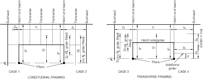
Figure 1.4.1 Hatch end beam
arrangements
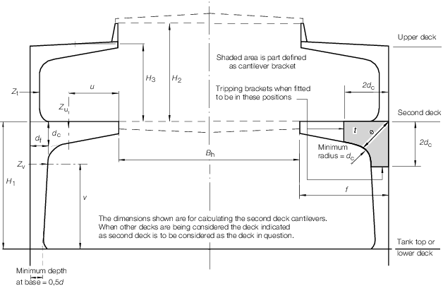
Figure 1.4.2 Deck cantilevers
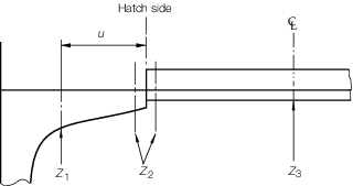
Figure 1.4.3 Section moduli of hatch end beams
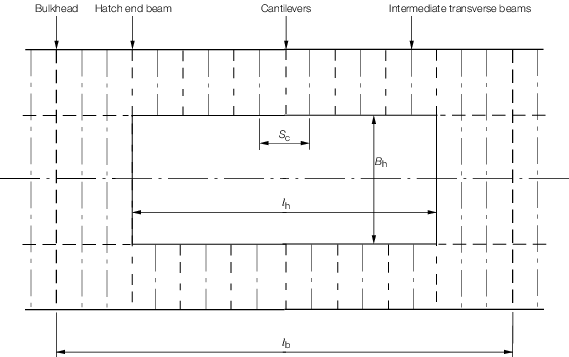
Figure 1.4.4 Deck supporting structure
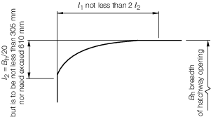
Figure 1.4.5 Elliptical and parabolic
corners
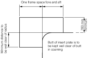
Figure 1.4.6 Insert plates for large
openings
|