
Section
1 Scantling requirements
1.1 Symbols
1.1.1 The symbols used in this Chapter are defined as follows:
|
g |
= |
acceleration due to gravity, 9,81 m/s2
|
1.2 Loading guidance
1.2.1 All units are to be provided with loading guidance information
containing sufficient information to enable the loading, unloading and ballasting
operations and inspection/ maintenance of the unit within the stipulated operational
limitations. The loading guidance information is to include an approved Loading
Manual and Loading Computer System complying with the requirements given in Pt 3, Ch 4, 8 Loading guidance information of the Rules and Regulations for the Classification of Ships (hereinafter
referred to as the Rules for Ships).
1.2.2 All relevant loading conditions and limitations are to be clearly stated
in the loading manual. The loading computer system should be installed to monitor
still water bending moments and shear forces and ensure they are maintained within
the approved permissible levels.
1.3 Hull girder bending strength
1.3.3
Hull girder requirement on total design bending moment.
- The net vertical hull girder section modulus requirement as
defined in Pt 10, Ch 3, 1.3 Hull girder bending strength 1.3.3.(b) is to be assessed for both hogging and sagging
conditions.
- The hull girder net section modulus,
 , about the horizontal neutral axis is not to be less than
the Rule required section modulus, based on the permissible still water and
design wave bending moments as follows: , about the horizontal neutral axis is not to be less than
the Rule required section modulus, based on the permissible still water and
design wave bending moments as follows:
 |
= |
 m3 m3
|
where
 |
= |
vertical hull girder net section modulus, in
m3, to be calculated in accordance with Ch
1,13.4.2. |
Table 3.1.1 Loads and
corresponding acceptance criteris for hull girder bending
assessment
| Design load combination
|
Still water bending moment, 
|
Vertical wave bending moment, 
|
Permissible hull girder bending stress,  see Note 1
|
| (S)
|

|
0
|
143/k
|
within 0,4L
amidships
|
| 105/k
|
at and forward of
0,9L from AP and at and aft of 0,1L
from AP
|
| (S + D)
|

|

|
190/k
|
within 0,4L
amidships
|
| 140/k
|
at and forward of
0,9L from AP and at and aft of 0,1L
from AP
|
| Symbols
|
 = permissible hull girder hogging and
sagging still water bending moment for Static (S) or
Static + Dynamic (S+D) design load combination, as
applicable from Pt 10, Ch 2, 6.1 Symbols 6.1.1 in Pt 10, Ch 2 Loads and Load Combinations,
for the load case under consideration, in kNm = permissible hull girder hogging and
sagging still water bending moment for Static (S) or
Static + Dynamic (S+D) design load combination, as
applicable from Pt 10, Ch 2, 6.1 Symbols 6.1.1 in Pt 10, Ch 2 Loads and Load Combinations,
for the load case under consideration, in kNm
|
 = hogging and sagging vertical wave
bending moments, in kNm, as defined in Pt 10, Ch 2, 3.7 Dynamic hull girder loads 3.7.1.(a) = hogging and sagging vertical wave
bending moments, in kNm, as defined in Pt 10, Ch 2, 3.7 Dynamic hull girder loads 3.7.1.(a)
|
|
|
 is to be taken as: is to be taken as:
|
|
|
 for assessment with respect to
hogging vertical wave bending moment for assessment with respect to
hogging vertical wave bending moment
|
|
|
 for assessment with respect to
sagging vertical wave bending moment for assessment with respect to
sagging vertical wave bending moment
|
| NOTES
|
1.  is to be linearly interpolated
between values given. is to be linearly interpolated
between values given.
|
| 2. For the flooded condition the permissible
hull girder bending stress is to be taken as equal to
the yield stress.
|
1.3.4 Hull girder section
- The following actual hull girder sectional properties are
required to be verified:
- vertical hull girder moment of
inertia, about the horizontal axis;
- hull girder section modulus about
the horizontal axis – at deck-at-side;
- hull girder section modulus about the horizontal axis –
at keel;
- hull girder section modulus about the vertical axis – at
side;
- hull girder vertical shear area.
- The minimum allowable hull girder section
properties are to be calculated with every member at a thickness equal to
its required net minimum thickness plus half the applicable corrosion
addition given in Pt 4, Ch 3, 7.3 Corrosion additions.
1.4 Hull girder shear strength
1.4.1
General.
- The hull girder shear strength requirements apply along the full
length of the hull girder, from AE to FP.
- The following requirements are applicable to units with
standard structural arrangements as shown in Table 3.1.2 Shear force distribution
factors. Alternative
configurations will be specially considered.
1.4.2
Assessment of hull girder shear strength.
- The net hull girder shear strength capacity,
 , is not to be less than the required vertical shear
force, , is not to be less than the required vertical shear
force,  : :
 |
= |
 kN kN |
where
- The permissible positive and negative still
water shear forces,
 , are to satisfy the following for each loading condition: , are to satisfy the following for each loading condition:
 ≤ ≤  — —  kN kN
for maximum permissible
positive shear force
 ≥ ≥  — —  kN kN
for minimum permissible
negative shear force
where
 |
= |
net hull girder vertical shear strength to be taken
as the minimum for all plate elements that contribute to the
hull girder shear capacity |
| = |
 kN kN |
 |
= |
net thickness of plate, in mm |
| = |
 — —  |
 |
= |
gross plate thickness, in mm. For corrugated
bulkheads, to be taken as the minimum of  and and  , in mm , in mm |
 |
= |
gross thickness of the corrugation web, in mm |
 |
= |
gross thickness of the corrugation flange, in mm |
 |
= |
unit shear flow per mm for the plate being
considered and based on the net scantlings. Where direct
calculation of the unit shear flow is not available, the unit
shear flow may be taken equal to |
| = |

|
Table 3.1.2 Shear force distribution
factors
| Hull configuration
|
fi
factors
|
Outside cargo region, no longitudinal bulkhead

|
Side
shell
|

|
Outside cargo region, centreline bulkhead

|
Side shell
|

|
| Longitudinal
bulkhead
|

|
Outside cargo region, two longitudinal
bulkheads
|
Side shell
|

|
| Longitudinal
bulkhead
|

|
Double hull, single cargo tank abreast
|
Side shell
|

|
| Inner hull
|

|
Double hull, one centreline bulkhead

|
Side shell
|

|
| Inner hull
|

|
| Longitudinal
bulkhead
|

|
Double hull, two centreline bulkheads
|
Side shell
|

|
| Inner hull
|

|
| Longitudinal
bulkhead
|

|
Double hull, two longitudinal bulkheads

|
Side shell
|

|
| Inner hull
|

|
| Longitudinal
bulkhead
|

|
| Symbols
|
|
i |
= |
index for the structural member under
consideration
1, for the side
shell
2, for the inner
hull
3, for the
longitudinal bulkhead
|
|
Ai-net50 |
= |
net area based on deduction
0,5tc, of the structural member, i, at
one side of the section under consideration. The
area A3-net50 for the centreline bulkhead
is not to be reduced for symmetry around the
centreline |
|
|
Note 1. The
effective net hull girder vertical shear area includes the
net plating area of the side shell including the bilge, the
inner hull including the hopper side and the outboard girder
under, the upper deck girder where applicable, and the
longitudinal bulkheads including the double bottom girders
in line.
Note 2. For
longitudinal strength members forming the web of the hull
girder which are inclined to the vertical, the area of the
member to be included in the shear force calculation is to
be based on the projected area onto the vertical
plane.
|
Table 3.1.3 Loads and corresponding
acceptance criteria for hull girder shear assessment
| Design load
combination
|
Still water
shear force,Qsw-perm
|
Vertical wave
shear force,Qwv
|
Permissible
shear stress,τperm, see Note
|
| (S)
|
Qsw-perm
|
0
|
105/k for plate ij
|
| (S + D)
|
Qsw-perm
|
Qwv
|
120/k for plate ij
|
| Symbols
|
|
Qsw-perm
|
= |
permissible positive or negative hull girder
still water shear force for Static (S) or Static +
Dynamic (S + D) design load combination, as applicable
from Table 2.6.1 Design load
combinations
for the load case under consideration, in kN |
|
Qwv
|
= |
positive or negative vertical wave shear,
in kN, as defined in Pt 10, Ch 2, 3.7 Dynamic hull girder loads 3.7.1.(a).
Qvw is to be taken as:
Qwv-pos for assessment with respect to
maximum positive permissible still water shear force
Qwv-neg for assessment
with respect to minimum negative permissible still
water shear force
|
|
plate ij |
= |
for each plate j, index i denotes the
structural member of which the plate forms a
component |
|
|
NOTE
For the flooded condition the permissible hull
girder shear stress is to be taken as equal to 0,58 yield
stress.
|
|
q1-net50
|
= |
first moment of area, in cm3, about the horizontal
neutral axis of the effective longitudinal members between the vertical
level at which the shear stress is being determined and the vertical
extremity, taken at the section being considered. The first moment of area
is to be based on the net thickness, tnet50
|
1.4.3
Shear force correction for longitudinal bulkheads between cargo tanks.
- For longitudinal bulkheads between cargo
tanks, the effective net plating thickness of the plating above the inner
bottom, tsfc-net50
for plate ij, used for calculation of hull girder shear strength,
Q
v-net50, may be corrected for local shear distribution and is
given by:
|
tsfc-net50
|
= |
tgrs
– 0,5tc
– tΔ
mm |
where
|
tgrs
|
= |
gross plate thickness, in mm |
- The vertical distribution of thickness
reduction for shear force correction is assumed to be triangular, as
indicated in Figure 3.1.1 Shear force
correction for longitudinal bulkheads. The thickness
deduction, tΔ, to account for shear force correction is to be
taken as:
|
tΔ
|
= |
 mm mm |
where
|
ltk
|
= |
length of cargo tank, in metres |
|
xblk
|
= |
the minimum longitudinal distance from section
considered to the nearest cargo tank transverse bulkhead, in
metres. To be taken positive and not greater than
0,5ltk
|
|
zp
|
= |
the vertical distance from the lower edge of plate
ij to the base line, in metres. Not to be taken as less than
hdb
|
|
τ
ij-perm
|
= |
permissible hull girder shear stress,
τperm, in N/mm2 for plate ij |
| = |
120/kij
|
- For ship units with one or two centreline
longitudinal bulkheads between the cargo tanks, the shear force correction
in way of transverse bulkhead, δQ3, is to be taken as:
where
- For ship units with one or two centreline
longitudinal bulkheads between the cargo tanks, the correction factor,
K3
, in way of transverse bulkheads is to be taken as:
|
K3
|
= |

|
where
|
n
|
= |
number of floors between transverse bulkheads |
- For ship units with two longitudinal
bulkheads between the cargo tanks, the shear force correction,
δQ3
, is to be taken as:
where

Figure 3.1.1 Shear force
correction for longitudinal bulkheads
- For ship units with two longitudinal
bulkheads between the cargo tanks, the correction factor, K3
, in way of transverse bulkheads is to be taken as:
|
K3
|
= |
 |
where
|
n
|
= |
number of floors between transverse bulkheads |
|
r
|
= |
ratio of the part load carried by the wash
bulkheads and floors from longitudinal bulkhead to the double
side and is given by |
|
r
|
= |

|
NOTE
For preliminary calculations,
r may be taken as 0,5
|
ltk
|
= |
length of cargo tank, between transverse bulkheads
in the side cargo tank, in metres |
|
b80
|
= |
80 per cent of the distance from longitudinal
bulkhead to the inner hull longitudinal bulkhead, in metres, at
tank mid length |
|
AT-net50
|
= |
net shear area of the transverse wash bulkhead,
including the double bottom floor directly below, in the side
cargo tank, in cm2, taken as the smallest area in a
vertical section. AT-net50 is to be calculated with
net thickness given by tgrs
– 0,5tc
|
|
n5
|
= |
number of wash bulkheads in the side cargo
tank |
|
R
|
= |
total efficiency of the transverse primary support
members in the side tank |
|
R
|
= |
 cm2 cm2
|
|
γ
|
= |

|
|
AQ-net50
|
= |
net shear area, in cm2, of a transverse
primary support member in the wing cargo tank, taken as the sum
of the net shear areas of floor, cross ties and deck transverse
webs
AQ-net50
is to be calculated using the net thickness given by
tgrs
– 0,5tc
.The net shear area is to be calculated at the midspan
of the members
|
|
Ipsm–net50
|
= |
net moment of inertia for primary support members,
in cm4, of a transverse primary support member in the
wing cargo tank, taken as the sum of the moments of inertia of
transverses and cross ties. It is to be calculated using the net
thickness given by tgrs
– 0,5tc
. The net moment of inertia is to be calculated at the
midspan of the member, including an attached plate width equal
to the primary support member spacing |
|
tgrs
|
= |
gross plate thickness, in mm |
- The maximum resulting force on the double
bottom in a tank, Fdb
, is to be taken as:
|
Fdb
|
= |
g |WCT
+ WCWBT
– ρsw
b2 ltk Tmean
| kN |
where
|
ltk
|
= |
length of cargo tank, between watertight transverse
bulkheads in the wing cargo tank, in metres |
|
Tmean
|
= |
draught at the mid length of the tank for the
loading condition considered, in metres. |
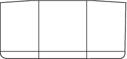
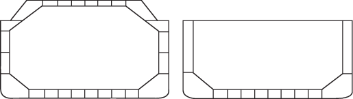
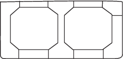
Table 3.1.4 Design conditions
for double bottoms
| Structural configuration
|
WCT
|
WCWBT
|
b2
|
| Ship units with
one longitudinal bulkhead
|
Weight of cargo in
cargo tanks, in tonnes, using a minimum specific gravity
of 1,025 tonnes/m3
|
Weight of ballast
between port and starboard inner sides, in
tonnes
|
Maximum breadth
between port and starboard inner sides at mid length of
tank, in metres, as shown in Figure 3.1.2 Tank breadth to be
included for standard tank configuration
|
| Ship units with two
cargo tanks abreast with a centreline cofferdam
|
Weight of cargo in
cargo tanks, in tonnes, using the specific gravity of
the cargo as shown inTable 2.1.1 Minimum density of
liquid for strength and fatigue assessment in Pt 10, Ch 2 Loads and Load Combinations
for strength assessment
|
Weight of ballast
below the cargo tanks, in tonnes
|
Total breadth of
the portion of the ballast tanks below the cargo tanks,
in metres as shown in Figure 3.1.2 Tank breadth to be
included for standard tank configuration
|
| Ship units with two
longitudinal bulkheads
|
Weight of cargo in
the centre tank, in tonnes, using a minimum specific
gravity of 1,025 tonnes/m3
|
Weight of ballast
below the centre cargo tank, in tonnes
|
Maximum breadth of
the centre cargo tank at mid length of tank, in metres,
as shown in Figure 3.1.2 Tank breadth to be
included for standard tank configuration
|
| Ship units with a
single cargo tank abreast
|
Weight of cargo in
cargo tank, in tonnes, using the specific gravity of the
cargo as shown in Table 2.1.1 Minimum density of
liquid for strength and fatigue assessment
for strength assessment
|
Weight of ballast
below the cargo tank, in tonnes
|
Breadth of the
ballast tanks below the cargo tank, in metres, as shown
in Figure 3.1.2 Tank breadth to be
included for standard tank configuration
|
- The maximum resulting force on the double
bottom in a tank, Fdb
, is in no case to be less than that given by the Rule minimum
conditions given in Table 3.1.5 Rule minimum
conditions for double bottoms. Where other tank
configurations are proposed, the equivalent loading scenario is to be
considered.
Table 3.1.5 Rule minimum
conditions for double bottoms
| Structural configuration
|
Positive/negative force, Fdb
|
Minimum condition
|
| Ship
units with one longitudinal bulkhead
|
Max. positive net
vertical force, Fdb
+
|
0,9TSC
and empty cargo and ballast tanks
|
| Max. negative net
vertical force, Fdb
–
|
0,6TSC
and full cargo tanks and empty ballast tanks
|
| Ship
units with two longitudinal bulkheads
|
Min. positive net
vertical force, Fdb
+
|
0,9TSC
and empty cargo and ballast tanks
|
| Min. negative net
vertical force, Fdb
–
|
0,6TSC
and full centre cargo tank and empty ballast tanks
|
- The effective net plating thickness of the plating, tsfc-net50, used for
calculation of hull girder shear strength, Qv-net50, is to
comply with the minimum thickness requirements for the cargo region given in
Pt 10, Ch 3, 2.2 General 2.2.4 and Pt 10, Ch 3, 2.2 General 2.2.5.
- The structure is to be subsequently confirmed as compliant using direct
calculations in terms of both stress and buckling.
1.4.4
Shear force correction due to loads from transverse bulkhead stringers.
- In way of transverse bulkhead stringer
connections, within areas as specified in Figure 3.1.4 Region for
stringer correction, tij, for a unit with three stringers, the
equivalent net thickness of plate used for calculation of the hull girder
shear strength, tstr-k
, where the index k refers to the identification number of the
stringer, is not to be taken greater than:
|
tstr-k
|
= |
 mm mm
τstr is not to
be taken greater than τif-perm
|
where
|
τij-perm
|
= |
permissible hull girder shear stress,
τperm
, for plate ij |
| = |
120/kij
N/mm2
|
|
τstr
|
= |
 N/mm2 N/mm2
|
|
Qstr-k
|
= |
shear force on the longitudinal bulkhead from the
stringer in loaded condition with tanks abreast full |
| = |
 kN kN |
|
zstr
|
= |
the vertical distance from baseline to the
considered stringer, in metres. |

Figure 3.1.2 Tank breadth to be
included for standard tank configuration
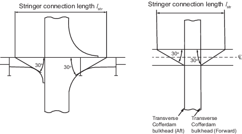
Figure 3.1.3 Effective
connection length of stringer
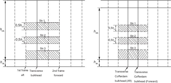
Figure 3.1.4 Region for
stringer correction, tij, for a unit with three stringers
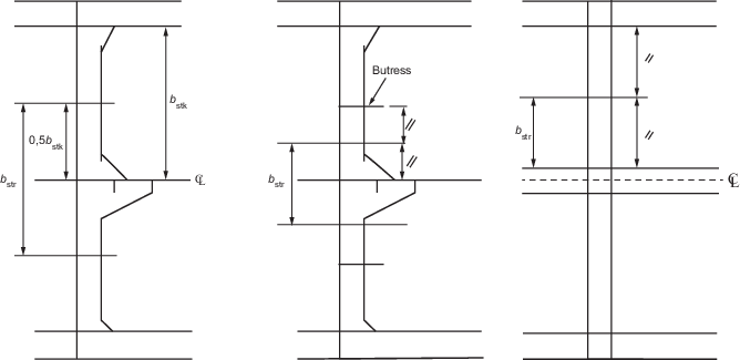
Figure 3.1.5 Load breadth of
stringers for units with a one or two centreline longitudinal
bulkheads
- The total stringer supporting force,
Fstr-k
, in way of a longitudinal bulkhead is to be taken as:
|
Fstr-k
|
= |
 |
where
|
Pstr
|
= |
pressure on stringer, in kN/m2, to be
taken as ρgh
tt |
|
htt
|
= |
the height from the top of the tank to the midpoint
of the load area between hk
/2 below the stringer and hk-1
/2 above the stringer, in metres |
|
hk
|
= |
the vertical distance from the considered stringer
to the stringer below. For the lowermost stringer, it is to be
taken as 80 per cent of the average vertical distance to the
inner bottom, in metres |
|
hk-1
|
= |
the vertical distance from the considered stringer
to the stringer above. For the uppermost stringer, it is to be
taken as 80 per cent of the average vertical distance to the
upper deck, in metres |
|
g |
= |
acceleration due to gravity, 9,81 m/s2 |
- Where reinforcement is provided to meet the above requirement,
the reinforced area based on tstr-k
is to extend longitudinally for the full length of the stringer
connection and a minimum of one frame spacing forward and aft of the
bulkhead. The reinforced area shall extend vertically from above the
stringer level and down to 0,5hk
below the stringer, where hk
, the vertical distance from the considered stringer to the stringer
below, is as defined in Pt 10, Ch 3, 1.4 Hull girder shear strength 1.4.4.(b). For the lowermost stringer, the
plate thickness requirementtstr-k
is to extend down to the inner bottom, see Figure 3.1.5 Load breadth of
stringers for units with a one or two centreline longitudinal
bulkheads.
- The equivalent net thickness of plate used for calculation of the hull
girder shear strength, tstr-k, is to comply with the
minimum thickness requirements for the cargo region given in Pt 10, Ch 3, 2.2 General 2.2.4 and Pt 10, Ch 3, 2.2 General 2.2.5.
- The structure is to be subsequently confirmed as compliant using direct
calculations in terms of both stress and buckling.
1.5 Hull girder buckling strength
1.5.1
General.
- These requirements apply to plate panels and longitudinals
subject to hull girder compression and shear stresses. These stresses are to
be based on the permissible values for wave bending moments and shear forces
given in Pt 10, Ch 2, 2.2 Static hull girder loads and Pt 10, Ch 2, 3.7 Dynamic hull girder loads.
- The hull girder buckling strength requirements apply along the
full length of the ship unit, from AE to FE.
- For the purposes of assessing the hull girder buckling strength
in this sub-Section, the following are to be considered separately:
- Axial hull girder compressive stress to satisfy
requirements in Pt 10, Ch 3, 1.5 Hull girder buckling strength 1.5.2.(f) and Pt 10, Ch 3, 1.5 Hull girder buckling strength 1.5.2.(h).
- Hull girder shear stress to satisfy requirements in
Pt 10, Ch 3, 1.5 Hull girder buckling strength 1.5.2.(g).
1.5.2
Buckling assessment.
- The buckling assessment of plate panels and
longitudinals is to be determined according to Pt 10, Ch 1, 17 Buckling, with hull girder stresses calculated on net hull girder
sectional properties.
- The buckling strength for the buckling
assessment is to be derived using local net scantlings, tnet
, as follows:
where
|
tgrs
|
= |
gross plate thickness, in mm |
- The hull girder compressive stress due to
bending, σhg-net50, for the buckling assessment is to be
calculated using net hull girder sectional properties and is to be taken as
the greater of the following:
|
σ
hg-net50
|
= |
 N/mm2 N/mm2
|
|
σ
hg-net50
|
= |
 N/mm2 N/mm2
|
where
|
z
|
= |
distance from the structural member under
consideration to the baseline, in metres |
|
zNA-net50
|
= |
distance from the baseline to the horizontal
neutral axis, in metres |
|
Iv-net50
|
= |
net vertical hull girder section moment of inertia,
in m4. |
- The sagging bending moment values of
Msw-perm
and Mwv-v
, are to be taken for members above the neutral axis. The hogging
bending moment values are to be taken for members below the neutral axis.
- The design hull girder shear stress for the
buckling assessment, τhg-net50, is to be calculated based on net hull girder
sectional properties and is to be taken as:
|
τ
hg-net50
|
= |
 N/mm2 N/mm2
|
where
|
Qwv
|
= |
positive or negative vertical wave shear, in kN, as
defined in Pt 10, Ch 2 Loads and Load Combinations
Qwv
is to be taken as:
Qwv-pos
for assessment with the positive permissible still water
shear force
Qwv-neg
for assessment with the negative permissible still water
shear force
|
|
tij-net50
|
= |
net thickness for the plate ij, in mm |
| = |
tij-grs
− 0,5tc
|
|
tij-grs
|
= |
gross plate thickness of plate ij, in mm. The gross
plate thickness for corrugated bulkheads is to be taken as the
minimum of tw-grs
and tf-grs
, in mm |
|
tw-grs
|
= |
gross thickness of the corrugation web, in mm |
|
tf-grs
|
= |
gross thickness of the corrugation flange, in
mm |
NOTES
1. Maximum of the positive shear
(still water + vertical wave) and negative shear (still water + vertical
wave) is to be used as the basis for calculation of design shear stress.
2. All plate elements ij that contribute to the hull
girder shear capacity are to be assessed. See also
Table 3.1.3 Loads and corresponding
acceptance criteria for hull girder shear assessment and Table 3.1.2 Shear force distribution
factors.
- The compressive buckling strength of plate
panels is to satisfy the following criteria:
η ≥
ηallow
where
|
η
|
= |
buckling utilisation factor |
| = |

|
|
σ
cr
|
= |
critical compressive buckling stress,
σxcr or σycr as appropriate, in
N/mm2, as specified in Pt 10, Ch 1, 17.2 Buckling of plates 17.2.1.(c). The critical compressive buckling stress is
to be calculated for the effects of hull girder compressive
stress only. The effects of other membrane stresses and lateral
pressure are to be ignored. The net thickness given as
tgrs
– tc
as described in Pt 10, Ch 1, 12 Corrosion additions is to be used for the calculation of
σcr
|
|
η
allow
|
= |
allowable buckling utilisation factor |
| = |
1,0 for plate panels at or above 0,5D
|
| = |
0,90 for plate panels below 0,5D
|
|
tgrs
|
= |
gross plate thickness, in mm |

Figure 3.1.6 Load breadth of
stringers for units with two inner longitudinal bulkheads
- The shear buckling strength of plate panels,
is to satisfy the following criteria:
η ≤ ηallow
where
|
η |
= |
buckling utilisation factor |
| = |

|
|
τ
cr
|
= |
critical shear buckling stress, in N/mm2,
specified in Pt 10, Ch 1, 17.2 Buckling of plates 17.2.1.(c). The critical shear buckling stress is to be
calculated for the effects of hull girder shear stress only. The
effects of other membrane stresses and lateral pressure are to
be ignored. The net thickness tgrs
– tc
as described in Pt 10, Ch 1, 12 Corrosion additions is to be used for the calculation of
τcr
|
|
η
allow
|
= |
allowable buckling utilisation factor |
| = |
0,95 |
|
tgrs
|
= |
gross plate thickness, in mm |
- The compressive buckling strength of
longitudinal stiffeners is to satisfy the following criteria:
η ≤ ηallow
where
|
η
allow
|
= |
allowable buckling utilisation factor |
|
|
= |
1,0 for stiffeners at or above 0,5D
|
| = |
0,90 for stiffeners below 0,5D. |
1.6 Tapering and structural continuity of
longitudinal hull girder elements
1.6.2
Longitudinal extent of higher strength steel.
- Where used, the application of higher strength steel is to be
continuous over the length of the ship unit up to locations where the
longitudinal stress levels are within the allowable range for mild steel
structure.
1.6.3
Vertical extent of higher strength steel.
- The vertical extent of higher strength steel, z
hts, used in the deck or bottom and measured from the moulded
deck line at side or keel is not to be taken less than the following, see
also Figure 3.1.7 Vertical extent of
higher strength steel.
|
zhts
|
= |
 |
where
|
z1
|
= |
distance from horizontal neutral axis to moulded
deck line or keel respectively, in metres |
|
σ
1
|
= |
to be taken as σdk or σkl for
the hull girder deck and keel respectively, in N/mm2
|
|
σ
dk
|
= |
hull girder bending stress at moulded deck line
given by
 N/mm2 N/mm2
|
|
σ
kl
|
= |
hull girder bending stress at keel given by
 N/mm2 N/mm2
|
|
Mwv-v
|
= |
hogging and sagging vertical wave bending moments,
in kNm, as defined in Pt 10, Ch 2, 1.2 Definitions 1.2.2.(d). Mwv-v is to be taken as:
Mwv-hog
for assessment with respect to hogging vertical wave
bending moment
Mwv-sag
for assessment with respect to sagging vertical wave
bending moment
|
|
Iv-net50
|
= |
net vertical hull girder moment of inertia, in
m4
|
|
zdk-side
|
= |
distance from baseline to moulded deck line at side,
in metres |
|
zkl
|
= |
vertical distance from the baseline to the keel, in
metres |
|
zNA-net50
|
= |
distance from baseline to horizontal neutral axis,
in metres |

Figure 3.1.7 Vertical extent of
higher strength steel
1.6.4
Tapering of plate thickness due to hull girder shear requirement.
- Longitudinal tapering of shear reinforcement is permitted,
provided that the requirements given in Pt 10, Ch 3, 1.4 Hull girder shear strength 1.4.2 are complied with for any longitudinal position.
1.6.5
Structural continuity of longitudinal bulkheads.
- Suitable scarphing arrangements are to be made to ensure
continuity of strength and the avoidance of abrupt structural changes. In
particular, longitudinal bulkheads are to be terminated at an effective
transverse bulkhead and large transition brackets shall be fitted in line
with the longitudinal bulkhead.
1.6.6
Structural continuity of longitudinal stiffeners.
- Where longitudinal stiffeners terminate, and are replaced by a
transverse system, adequate arrangements are to be made to avoid an abrupt
changeover.
- Where a deck longitudinal stiffener is cut, in way of an
opening, compensation is to be arranged to ensure structural continuity of
the area. The compensation area is to extend well beyond the forward and aft
ends of the opening and not be less than the area of the longitudinal that
is cut. Stress concentration in way of the stiffener termination and the
associated buckling strength of the plate and panel is to be
considered.
1.7 Standard construction details
1.7.1 Details to be submitted:
- A booklet of standard construction details is to be submitted
for review. It is to include the following:
- the proportions of built-up members to demonstrate
compliance with established standards for structural stability.
- the design of structural details which reduce the
harmful effects of stress concentrations, notches and material
fatigue, such as:
- details of the ends, at the intersections of
members and associated brackets;
- shape and location of air, drainage, and/or
lightening holes;
- shape and reinforcement of slots or cut-outs
for internals;
- elimination or closing of weld scallops in way
of butts, ‘softening’ of bracket toes, reduction of abrupt
changes of section or structural discontinuities;
- proportion and thickness of structural members
to reduce fatigue response due to machinery operational
and/or wave induced cyclic stresses, particularly for higher
strength steels.
1.8 Termination of local support
members
1.8.1
General.
- In general, structural members are to be effectively connected
to adjacent structures to avoid hard spots, notches and stress
concentrations.
- Where a structural member is terminated, structural continuity
is to be maintained by suitable back-up structure fitted in way of the end
connection of frames, or the end connection is to be effectively extended
with additional structure and integrated with an adjacent beam, stiffener,
etc.
- All types of stiffeners (longitudinals, beams, frames, bulkhead
stiffeners) are to be connected at their ends. However, in special cases,
sniped ends may be permitted. Requirements for the various types of
connections (bracketed, bracketless or sniped ends) are given in Pt 10, Ch 3, 1.8 Termination of local support members 1.8.3 to Pt 10, Ch 3, 1.8 Termination of local support members 1.8.5.
1.8.2
Longitudinal members.
- All longitudinals are to be kept continuous within the
0,4L amidships cargo tank region. In special cases, in way of
large openings, foundations and partial girders, the longitudinals may be
terminated, but end connection and welding are to be specially considered.
- Where continuity of strength of longitudinal members is provided
by brackets, the correct alignment of the brackets on each side of the
primary support member is to be ensured, and the scantlings of the brackets
are to be such that the combined stiffener/bracket section modulus and
effective cross-sectional area are not less than those of the member.
1.8.3
Bracketed connections.
- At bracketed end connections, continuity of strength is to be
maintained at the stiffener connection to the bracket and at the connection
of the bracket to the supporting member. The brackets are to have
scantlings, sufficient to compensate for the non-continuous stiffener flange
or noncontinuous stiffener.
- The arrangement of the connection between the stiffener and the
bracket is to be such that at no point in the connection is the section
modulus less than that required for the stiffener.
- Minimum net bracket thickness,
tbkt-net, is to be taken as:
|
tbkt-net
|
= |
 mm mm |
but is not to be less than 6 mm and need not be greater
than 13,5 mm
where:
|
fbkt
|
= |
0,2 for brackets with flange or edge stiffener |
| = |
0,3 for brackets without flange or edge
stiffener |
|
Zrl-net
|
= |
net Rule section modulus, for the stiffener, in
cm3.
In the case of two
stiffeners connected, it need not be taken as greater than
that of the smallest connected stiffener
|
|
σ
yd-stf
|
= |
specified minimum yield stress of the material of
the stiffener, in N/mm2
|
|
σ
yd-bkt
|
= |
specified minimum yield stress of the material of
the bracket, in N/mm2. |

Figure 3.1.8 Bracket arm
length
- Brackets to provide fixity of end rotation are to be fitted at
the ends of discontinuous local support members, except as otherwise
permitted by Pt 10, Ch 3, 1.8 Termination of local support members 1.8.4 The end brackets are to have arm lengths,
lbkt
, not less than:
|
lbkt
|
= |
 mm, but is not to be less than: mm, but is not to be less than: |
- 1,8 times the depth of the stiffener web for
connections where the end of the stiffener web is supported and the
bracket is welded in line with the stiffener web or with offset
necessary to enable welding, see Figure 3.1.8 Bracket arm
length (c)
- 2,0 times for other cases, see Figure 3.1.8 Bracket arm
length (a), (b) and (d)
where
|
cbkt
|
= |
65 for brackets with flange or edge stiffener |
| = |
70 for brackets without flange or edge
stiffener |
|
Zrl-net
|
= |
net Rule section modulus, for the stiffener, in
cm3. In the case of two stiffeners connected, it
need not be taken as greater than that of the smallest connected
stiffener |
- Where an edge stiffener is required, the depth of stiffener
web, dw
, is not to be less than:
|
dw
|
= |
 mm, mm,
but is not to be less than
50 mm
|
where
|
Zrl-net
|
= |
net Rule section modulus, for the stiffener, in
cm3. In the case of two stiffeners connected, it
need not be taken as greater than that of the smallest connected
stiffener. |
1.8.4
Bracketless connections.
- Local support members, for example, longitudinals, beams, frames
and bulkhead stiffeners forming part of the hull structure, are generally to
be connected at their ends, in accordance with the requirements of Pt 10, Ch 3, 1.8 Termination of local support members 1.8.2 and Pt 10, Ch 3, 1.8 Termination of local support members 1.8.3.
- Where alternative connections are adopted, the proposed
arrangements will be specially considered.
- The design of end connections and their supporting structure is
to be such as to provide adequate resistance to rotation and displacement of
the joint.
1.8.5
Sniped ends.
- Stiffeners with sniped ends may be used where dynamic loads are
small and where the incidence of vibration is considered to be small, i.e.
structure not in the stern area and structure not in the vicinity of engines
or generators, provided the net thickness of plating supported by the
stiffener, tp-net, is not less than:
|
tp-net
|
= |
 mm mm |
where
|
l
|
= |
stiffener span, in metres |
|
s
|
= |
stiffener spacing, in mm |
|
P
|
= |
design pressure for the stiffener for the design
load set being considered, in kN/m2. The design load
sets and method to derive the design pressure are to be taken in
accordance with the following criteria, which define the
acceptance criteria set to be used: |
- Table 3.2.4 Section modulus
requirements for stiffeners in the cargo tank
region
-
Pt 10, Ch 3, 3.11 Scantling requirements 3.11.2.(b) in the area forward of the forward
cargo tank, and in the aft end
- Pt 10, Ch 3, 4.9 Scantling requirements 4.9.1 in the machinery space
|
c1
|
= |
coefficient for the design load set being
considered, to be taken as: |
| = |
1,2 for acceptance criteria set AC1 |
| = |
1,1 for acceptance criteria set AC2 |
| = |
1,0 for acceptance criteria set AC3. |
- Bracket toes and sniped end members are, in general, to be kept
within 25 mm of the adjacent member. The maximum distance is not to exceed
40 mm unless the bracket or member is supported by another member on the
opposite side of the plating. Special attention is to be given to the end
taper by using a sniped end of not more than 30 degrees. The depth of toe or
sniped end is, generally, not to exceed the thickness of the bracket toe or
sniped end member, but need not be less than 15 mm.
- The end attachments of non-load-bearing members may be snipe
ended. The sniped end is to be not more than 30 degrees and is generally to
be kept within 50 mm of the adjacent member, unless it is supported by a
member on the opposite side of the plating. The depth of the toe is
generally not to exceed 15 mm.
1.8.6
Air and drain holes and scallops.
- Air and drain holes and scallops are to be kept at least 200 mm
clear of the toes of end brackets, end connections and other areas of high
stress concentration measured along the length of the stiffener toward the
midspan and 50 mm measured along the length in the opposite direction, see
Figure 3.1.10 Location of air
and drain holes. Openings that have been fitted
with closing plates, such as scallops, may be permitted in way of block
fabrication butts. In areas where the shear stress is less than 60 per cent
of the allowable limit, alternative arrangements may be accepted. Openings
are to be well-rounded. Figure 3.1.9 Examples of air
and drain holes and scallops shows some examples of air and
drain holes and scallops. In general, the ratio of a/b, as defined in Figure 3.1.9 Examples of air
and drain holes and scallops, is to be between 0,5 and 1,0.
In fatigue-sensitive areas, further consideration may be required with
respect to the details and arrangements of openings and scallops.

Figure 3.1.9 Examples of air
and drain holes and scallops

Figure 3.1.10 Location of air
and drain holes
1.8.7
Special requirements.
- Closely spaced scallops or drain holes, i.e. where the distance
between scallops/drain holes is less than twice the width b as shown
in Figure 3.1.9 Examples of air
and drain holes and scallops, are not permitted in longitudinal strength
members or within 20 per cent of the stiffener span measured from the end of
the stiffener. Widely spaced air or drain holes may be permitted, provided
that they are of elliptical shape or equivalent to minimise stress
concentration and are, in general, cut clear of the weld connection.
1.9 Termination of primary support
members
1.9.1
General.
- Primary support members are to be arranged to ensure effective
continuity of strength. Abrupt changes of depth or section are to be
avoided. Primary support members in tanks are to form a continuous line of
support and, wherever possible, a complete ring system.
- The members are to have adequate lateral stability and web
stiffening, and the structure is to be arranged to minimise hard spots and
other sources of stress concentration. Openings are to have well-rounded
corners and are to be located considering the stress distribution and
buckling strength of the panel.
1.9.2
End connection.
- Primary support members are to be provided with adequate end
fixity by brackets or equivalent structure. The design of end connections
and their supporting structure is to provide adequate resistance to rotation
and displacement of the joint and effective distribution of the load from
the member.
- The ends of brackets are generally to be soft-toed. The free
edges of the brackets are to be stiffened. Scantlings and details are given
in Pt 10, Ch 3, 1.9 Termination of primary support members 1.9.3.
- Where primary support members are subjected
to concentrated loads, additional strengthening may be required,
particularly if these are out of line with the member web.
- In general, ends of primary support members or connections
between primary support members forming ring systems are to be provided with
brackets. Bracketless connections may be applied, provided that there is
adequate support of the adjoining face-plates.
1.9.3
Brackets.
- In general, the arm lengths of brackets connecting primary
support members are not to be less than the web depth of the member, and
need not be taken as greater than 1,5 times the web depth. The thickness of
the bracket is, in general, not to be less than that of the girder web
plate.
- For a ring system where the end bracket is integral with the
webs of the members and the face-plate is carried continuously along the
edges of the members and the bracket, the full area of the largest
face-plate is to be maintained close to the mid point of the bracket and
gradually tapered to the smaller face-plates. Butts in face-plates are to be
kept well clear of the bracket toes.
- Where a wide face-plate abuts a narrower one, the taper is
generally not to be greater than 1 in 4. Where a thick face-plate abuts
against a thinner one and the difference in thickness is greater than 4 mm,
the taper of the thickness is not to be greater than 1 in 3.
- Face-plates of brackets are to have a net cross-sectional area,
Af-net
, which is not to be less than:
|
Af-net
|
= |
lbkt-edge tbkt-net
cm |
where
|
lbkt-edge
|
= |
length of free edge of bracket, in metres. For
brackets that are curved, the length of the free edge may be
taken as the length of the tangent at the mid point of the free
edge. If lbkt-edge
is greater than 1,5 m, 40 per cent of the face-plate area
is to be in a stiffener fitted parallel to the free edge and a
maximum 0,15 m from the edge |
1.9.4
Bracket toes.
- The toes of brackets are not to land on unstiffened plating.
Notch effects at the toes of brackets may be reduced by making the toe
concave or otherwise tapering it off. In general, the toe height is not to
be greater than the thickness of the bracket toe, but need not be less than
15 mm. The end brackets of large primary support members are to be
soft-toed. Where any end bracket has a face-plate, it is to be sniped and
tapered at an angle not greater than 30 degrees.
- Where primary support members are constructed of higher strength
steel, particular attention is to be paid to the design of the end bracket
toes in order to minimise stress concentrations. Sniped face-plates, which
are welded onto the edge of primary support member brackets, are to be
carried well around the radiused bracket toe and are to incorporate a taper
not greater than 1 in 3. Where sniped face-plates are welded adjacent to the
edge of primary support member brackets, an adequate cross-sectional area is
to be provided through the bracket toe at the end of the snipe. In general,
this area, measured perpendicular to the face-plate, is to be not less than
60 per cent of the full cross-sectional area of the face-plate, see Figure 3.1.11 Bracket toe
construction.

Figure 3.1.11 Bracket toe
construction
1.10 Intersections of continuous local support
members and primary support members
1.10.1
General.
- Cut-outs for the passage of stiffeners through the web of
primary support members, and the related collaring arrangements, are to be
designed to minimise stress concentrations around the perimeter of the
opening and on the attached web stiffeners.
- Cut-outs in way of cross-tie ends and floors under bulkhead
stools or in high stress areas are to be fitted with ‘full’ collar plates,
see Figure 3.1.12 Collars for
cut-outs in areas of high stress.

Figure 3.1.12 Collars for
cut-outs in areas of high stress
- Lug type collar plates are to be fitted in cut-outs where
required for compliance with the requirements of Pt 10, Ch 3, 1.10 Intersections of continuous local support members and primary support members 1.10.3, and in areas of significant stress concentrations, e.g.
in way of primary support member toes.
- When, in the following locations, the calculated direct stress,
σw, in the primary support member web stiffener according to
Pt 10, Ch 3, 1.10 Intersections of continuous local support members and primary support members 1.10.3.(e) exceeds 80 per cent of the permissible values, a soft
heel is to be provided in way of the heel of primary support member web
stiffeners:
- connection to shell envelope longitudinals below the
deep load draught, Tsc
;
- connection to inner bottom longitudinals.
A soft heel is not required at the intersection with
watertight bulkheads, where a back bracket is fitted or where the
primary support member web is welded to the stiffener faceplate. The
soft heel is to have a keyhole, similar to that shown in Figure 3.1.14 Primary support
member web stiffener details (c).
1.10.2
Details of cut-outs.
- In general, cut-outs are to have rounded corners and the corner
radii, R, are to be as large as practicable, with a minimum of 20 per
cent of the breadth, b, of the cut-out or 25 mm, whichever is
greater, but need not be greater than 50 mm, see Figure 3.1.12 Collars for
cut-outs in areas of high stress. Consideration will be given to other shapes
on the basis of maintaining equivalent strength and minimising stress
concentration.
1.10.3
Connection between primary support members and intersecting stiffeners (local
support members).
- The cross-sectional areas of the connections
are to be determined from the proportion of load transmitted through each
component in association with its appropriate permissible stress.
- The total load, W, transmitted
through the connection to the primary support member is given by:
|
W |
= |
 |
where
|
P
|
= |
design pressure for the stiffener for the design
load set being considered, in kN/m2. The design load
sets, method to derive the design pressure and applicable
acceptance criteria set are to be taken in accordance with the
following criteria, which define the acceptance criteria set to
be used:
- Table 3.2.4 Section modulus
requirements for stiffeners in the cargo tank
region
- Pt 10, Ch 3, 3.11 Scantling requirements 3.11.2.(a) in the area forward of the forward
cargo tank
- Pt 10, Ch 3, 3.11 Scantling requirements 3.11.2.(a) in the aft end
- Pt 10, Ch 3, 4.9 Scantling requirements 4.9.1 in the machinery space
- Pt 10, Ch 3, 6 Evaluation of structure for sloshing and impact loads if subjected to sloshing loads
- Pt 10, Ch 3, 6 Evaluation of structure for sloshing and impact loads if subjected to bottom slamming
loads
- Pt 10, Ch 3, 6 Evaluation of structure for sloshing and impact loads if subjected to bow impact loads
|
|
S
|
= |
primary support member spacing, in metres |
|
s
|
= |
stiffener spacing, in mm |
For stiffeners having different primary support member
spacing, S, and/or different pressure, P, at each side of
the primary support member, the average load for the two sides is to be
applied, e.g. vertical stiffeners at transverse bulkhead.
- The load, W1
, transmitted through the shear connection is to be taken as follows:
If the web stiffener is connected to the intersecting
stiffener:
|
W1
|
= |
 kN kN |
If the web stiffener is not connected to the
intersecting stiffener:
where
|
α
a
|
= |
panel aspect ratio, not to be taken greater than
0,25 |
| = |

|
|
S
|
= |
primary support member spacing, in metres |
|
s
|
= |
stiffener spacing, in mm |
|
A1-net
|
= |
effective net shear area of the connection, to be
taken as the sum of the components of the connection:
Ald-net
+ Alc-net
cm2
in case of a slit type
slot connections area, A1-net
, is given by:
Al-net
= 2ld tw-net
10–2 cm2
in
case of a typical double lug or collar plate connection
area, Al-net
, is given by:
Al-net
= 2f1 lc tc-net
10–2 cm2
|
|
ld
|
= |
length of direct connection between stiffener and
primary support member web, in mm |
|
tw-net
|
= |
net web thickness of the primary support member, in
mm |
|
lc
|
= |
length of connection between lug or collar plate
and primary support member, in mm |
|
tc-net
|
= |
net thickness of lug or collar plate, not to be
taken greater than the net thickness of the adjacent primary
support member web, in mm |
|
f1
|
= |
shear stiffness coefficient: |
| = |
1,0 for stiffeners of symmetrical cross-section |
| = |
 for stiffeners of asymmetrical cross-section
but is not to be taken as greater than 1,0 for stiffeners of asymmetrical cross-section
but is not to be taken as greater than 1,0 |
|
fc
|
= |
the collar load factor defined as follows: for
intersecting stiffeners of symmetrical cross-section: |
| = |
1,85 for Aw-net
≤ 14 |
| = |
1,85 – 0,0441 (Aw-net
– 14) for 14 < Aw-net
≤ 31 |
| = |
1,1 – 0,013 (Aw-net
– 31) for 31 < Aw-net
≤ 58 |
| = |
0,75 for Aw-net
> 58
for intersecting stiffeners of
asymmetrical cross-section:

|
where
|
ls
|
= |
lc
for a single lug or collar plate connection to the primary
support member |
| = |
ld
for a single sided direct connection to the primary support
member |
| = |
mean of the connection length on both sides, i.e.
in the case of a lug or collar plus a direct connection,
ls
= 0,5 (lc
+ ld
) |

Figure 3.1.13 Symmetric and
asymmetric cut-outs

Figure 3.1.14 Primary support
member web stiffener details
- The load, W2
, transmitted through the primary support member web stiffener is to be
taken as follows: If the web stiffener is connected to the intersecting
stiffener:
|
W2
|
= |
 kN kN |
If the web stiffener is not connected to the
intersecting stiffener:
where
|
S
|
= |
primary support member spacing, in metres |
|
s
|
= |
stiffener spacing, in mm |
- The values of Aw-net
, Awc-net
and A1–net
are to be such that the calculated stresses satisfy the following
criteria: for the connection to the primary support member web stiffener
away from the weld:
σ
w
≤ σperm
for the connection to the primary support member web
stiffener in way of the weld:
σ
wc ≤ σperm
for the
shear connection to the primary support member web:
τ
w
≤ τperm
where
|
σ
w
|
= |
direct stress in the primary support member web
stiffener at the minimum bracket area away from the weld
connection: |
| = |
 N/mm2 N/mm2
|
|
σ
wc
|
= |
direct stress in the primary support member web
stiffener in way of the weld connection: |
| = |
 N/mm2 N/mm2
|
|
τ
w
|
= |
shear stress in the shear connection to the primary
support member |
| = |
 N/mm2 N/mm2
|
|
τ
perm
|
= |
permissible shear stress given in Table 3.1.6 Permissible
stresses for connection between stiffeners and primary support
members for the applicable acceptance
criteria, see Pt 10, Ch 3, 1.10 Intersections of continuous local support members and primary support members 1.10.3.(b), in N/mm2
when
total load, W, is bottom slamming or bow impact
loads, the following criteria apply in lieu of Pt 10, Ch 3, 1.10 Intersections of continuous local support members and primary support members 1.10.3.(c) to Pt 10, Ch 3, 1.10 Intersections of continuous local support members and primary support members 1.10.3.(e)
|
0,9W ≤  kN kN
Table 3.1.6 Permissible
stresses for connection between stiffeners and primary support
members
| Item
|
Direct stress,
σperm, in N/mm2
|
Shear stress,
τperm, in N/mm2
|
| Acceptance criteria
set, see
Pt 10, Ch 3, 3.4 Side structure 3.4.3.(b)
|
Acceptance criteria
set, see
Pt 10, Ch 3, 3.4 Side structure 3.4.3.(b)
|
| AC1
|
AC2
|
AC3
|
AC1
|
AC2
|
AC3
|
| Primary support member web
stiffener
|
0,83σyd, see Note 3
|
σyd
|
σyd
|
—
|
—
|
—
|
| Primary support member web stiffener to
intersecting stiffener in way of weld
connection:
|
|
|
|
|
|
|
| double continuous fillet
|
0,58σyd
see Note 3
|
0,7σyd
see Note 3
|
σyd
|
—
|
—
|
—
|
| partial penetration weld
|
0,83σyd
see Notes 2 & 3
|
σyd
see Note 2
|
σyd
|
—
|
—
|
—
|
| Primary support member stiffener to
intersecting stiffener in way of lapped welding
|
0,5σyd
|
0,6σyd
|
σyd
|
—
|
—
|
—
|
| Shear connection including lugs or collar
plates:
|
|
|
|
|
|
|
| single sided connection
|
—
|
—
|
—
|
0,71τyd
|
0,85τyd
|
τyd
|
| double sided connection
|
—
|
—
|
—
|
0,83σyd
|
τyd
|
τyd
|
| Symbols
|
|
τperm
|
= |
permissible shear stress, in
N/mm2
|
|
σperm
|
= |
permissible direct stress, in
N/mm2
|
|
σyd
|
= |
minimum specified material yield
stress, in N/mm2
|
|
τyd
|
= |
 , in N/mm2 , in N/mm2
|
|
|
NOTES
1. The stress computation on plate type
members is to be performed on the basis of net
thicknesses, whereas gross values are to be used in
weld strength assessments, see Pt 10, Ch 3, 1.10 Intersections of continuous local support members and primary support members 1.10.3.(k).
2. The root face is not to be greater
than one third of the gross thickness of the primary
support member stiffener.
3. Allowable stresses may be increased
by 5 per cent where a soft heel is provided in way
of the heel of the primary support member web
stiffener.
|
- Where a backing bracket is fitted in addition
to the primary support member web stiffener, it is to be arranged on the
opposite side to, and in alignment with, the web stiffener. The arm length
of the bracket is to be not less than the depth of the web stiffener and its
net cross-sectional area through the throat of the bracket is to be included
in the calculation of Aw-net
as shown in Figure 3.1.14 Primary support
member web stiffener details.
- Lapped connections of primary support member
web stiffeners or tripping brackets to local support members are not
permitted in the cargo tank region, e.g. lapped connections between
transverse and longitudinal local support members.
- Fabricated stiffeners having their
face-plate welded to the side of the web, leaving the edge of the web
exposed, are not recommended for side shell and longitudinal bulkhead
longitudinals. Where such sections are connected to the primary support
member web stiffener, a symmetrical arrangement of connection to the
transverse members is to be incorporated. This may be implemented by fitting
backing brackets on the opposite side of the transverse web or bulkhead. In
way of the cargo tank region, the primary support member web stiffener and
backing brackets are to be butt welded to the intersecting stiffener
web.
- Where the web stiffener of the primary
support member is parallel to the web of the intersecting stiffener, but not
connected to it, the offset primary support member web stiffener may be
located as shown in Figure 3.1.15 Offset primary
support member web stiffeners. The offset primary support member web
stiffener is to be located in close proximity to the slot edge, see also
Figure 3.1.15 Offset primary
support member web stiffeners. The ends of the offset web stiffeners are to
be suitably tapered and softened.

Figure 3.1.15 Offset primary
support member web stiffeners
- Alternative arrangements will be specially
considered on the basis of their ability to transmit load with equivalent
effectiveness. Details of calculations made and/or testing procedures and
results are to be submitted.
- The size of the fillet welds is to be
calculated according to Pt 4, Ch 8 Welding and Structural Details, based on the weld
factors given in Table 3.1.7 Weld factors for
connection between stiffeners and primary support members. For the welding in way of the shear
connection, the size is not to be less than that required for the primary
support member web plate for the location under consideration.
Table 3.1.7 Weld factors for
connection between stiffeners and primary support members
| Item
|
Weld factor
|
| Primary support member stiffener to
intersecting stiffener
|
0,44 σwc / σperm not to
be less than 0,34
|
| Shear connection inclusive lug or collar
plate
|
0,34
|
| Shear connection inclusive lug or collar
plate, where the web stiffener of the primary support
member is not connected to the intersection
stiffener
|
0,44 τw / τperm not to
be less than 0,38
|
| Symbol
|
|
|
1.11 Openings
1.11.1
General.
- Openings are to have well rounded corners.
- Manholes, lightening holes and other similar openings are to be
avoided in way of concentrated loads and areas of high shear. In particular,
manholes and similar openings are to be avoided in high stress areas unless
the stresses in the plating and the panel buckling characteristics have been
calculated and found satisfactory. Examples of high stress areas include:
- in vertical or horizontal diaphragm plates in narrow
cofferdams/double plate bulkheads within one sixth of their length
from either end;
- in floors or double bottom girders close to their span
ends;
- above the heads and below the heels of pillars.
Where larger openings than given by Pt 10, Ch 3, 1.11 Openings 1.11.2 or Pt 10, Ch 3, 1.11 Openings 1.11.3 are proposed, the arrangements and compensation
required will be specially considered.
1.11.2
Manholes and lightening holes in single skin sections not requiring
reinforcement.
- Openings cut in the web with depth of opening not exceeding 25
per cent of the web depth and located so that the edges are not less than 40
per cent of the web depth from the face-plate do not generally require
reinforcement. The length of opening is not to be greater than the web depth
or 60 per cent of the local support member spacing, whichever is greater.
The ends of the openings are to be equidistant from the corners of cut-outs
for local support members.
1.11.3
Manholes and lightening holes in double skin sections not requiring
reinforcement.
- Where openings are cut in the web and are clear of high stress
areas, reinforcement of these openings is not required, provided that the
depth of the opening does not exceed 50 per cent of the web depth and is
located so that the edges are well clear of cut-outs for the passage of
local support members.
1.11.4
Manholes and lightening holes requiring reinforcement.
- Manholes and lightening holes are to be stiffened as required by
Pt 10, Ch 3, 1.11 Openings 1.11.4.(b) and Pt 10, Ch 3, 1.11 Openings 1.11.4.(c).
- The web plate is to be stiffened at openings
when the mean shear stress, as determined by application of the requirements
of Pt 10, Ch 3 Scantling Requirements, is greater than 50
N/mm22 for acceptance criteria set AC1 or greater than 60
N/mm2 for acceptance criteria sets AC2 and AC3. The
stiffening arrangement is to ensure buckling strength, as required by Pt 10, Ch 3 Scantling Requirements.
- On members contributing to longitudinal
strength, stiffeners are to be fitted along the free edges of the openings
parallel to the vertical and horizontal axis of the opening. Stiffeners may
be omitted in one direction if the shorter axis is less than 400 mm, and in
both directions if the length of both axes is less than 300 mm. Edge
reinforcement may be used as an alternative to stiffeners, see Figure 3.1.16 Web plate with
large openings

Figure 3.1.16 Web plate with
large openings
1.12 Local reinforcement
1.12.1
Reinforcement at knuckles.
- Whenever a knuckle in a main member (shell,
longitudinal bulkhead, etc.) is arranged, adequate stiffening is to be
fitted at the knuckle to transmit the transverse load. This stiffening, in
the form of webs, brackets or profiles, is to be connected to the transverse
members to which they are to transfer the load (in shear), see Figure 3.1.17 Example of
reinforcement at knuckles.

Figure 3.1.17 Example of
reinforcement at knuckles
- In general, for longitudinal shallow knuckles, closely spaced
carlings are to be fitted across the knuckle, between longitudinal members
above and below the knuckle. Carlings or other types of reinforcement need
not be fitted in way of shallow knuckles that are not subject to high
lateral loads and/or high inplane loads across the knuckle, such as deck
camber knuckles.
- Generally, the distance between the knuckle and the support
stiffening described in Pt 10, Ch 3, 1.12 Local reinforcement 1.12.2.(a) is not to be greater than 50 mm.
1.12.2
Reinforcement for openings and attachments associated with means of access for
inspection/ maintenance purposes.
- Local reinforcement is to
be provided, taking into account proper location and strength of all
attachments to the hull structure for access for inspection/maintenance
purposes.
|