
Section
8 Structural idealisation
8.1 General
8.2 Mixed steel grades
8.2.1 When a stiffener is of a higher strength material than the attached
plate, the yield stress used for the calculation of the section modulus requirements
in Pt 10, Ch 3 Scantling Requirements is, in general, not to be greater than 1,35
times the minimum specified yield stress of the attached plate. If the yield stress
of the stiffener exceeds this limitation, the following criterion is to be
satisfied:

where

|
= |
specified minimum yield stress of the material of the stiffener,
in N/mm2
|

|
= |
specified minimum yield stress of the material of the attached
plate, in N/mm2
|

|
= |
net section modulus, in way of face-plate/free edge of the
stiffener, in cm3
|

|
= |
net section modulus, in way of the attached plate of stiffener,
in cm3
|
8.3 Effective bending span of local support
members
8.3.2 The effective bending span may be reduced due to the presence of
brackets, provided the brackets are effectively supported by the adjacent structure,
otherwise the effective bending span is to be taken as the full length of the
stiffener between primary member supports.
8.3.4 The effective bending span may only be reduced where brackets are fitted
to the flange or free edge of the stiffener. Brackets fitted to the attached plating
on the side opposite to that of the stiffener are not to be considered as effective
in reducing the effective bending span.
8.4 Effective shear span of local support
members
8.4.3 The effective shear span may be reduced for brackets fitted on either
the flange or the free edge of the stiffener, or for brackets fitted to the attached
plating on the side opposite to that of the stiffener. If brackets are fitted at
both the flange or free edge of the stiffener, and to the attached plating on the
side opposite to that of the stiffener the effective shear span may be calculated
using the longer effective bracket arm.
8.4.4 The effective shear span may be reduced by a minimum of s/4000 m at each
end of the member, regardless of support detail, hence the effective shear span,
l
shr, is not to be taken greater than:
Where:
|
l
|
= |
full length of the stiffener between primary support members, in
m |
|
s
|
= |
stiffener spacing, in mm |
8.5 Effective shear span
8.5.1 The effective shear span of a stiffener may be reduced due to the
presence of brackets, provided the brackets are effectively supported by the
adjacent structure, otherwise the effective shear span is to be as the full length,
as given in Pt 10, Ch 1, 8.5 Effective shear span 8.5.3.
8.5.2 The effective shear span may be reduced for brackets fitted on either the
flange or the free edge of the stiffener, or for brackets fitted to the attached
plating on the side opposite to that of the stiffener. If brackets are fitted at
both the flange or free edge of the stiffener, and to the attached plating on the
side opposite to that of the stiffener, the effective shear span may be calculated
using the longer effective bracket arm.
8.5.3 The effective shear span may be reduced by a minimum of s/4000 m at each
end of the member, regardless of support detail, hence the effective shear span is
not to be taken greater than:

where
|
l
|
= |
full length of the stiffener between primary support members,
in metres |
|
s
|
= |
stiffener spacing, in mm. |
8.6 Effective elastic sectional properties of
local support members
8.7 Effective plastic section modulus and
shear area of stiffeners
8.7.2 The effective net plastic section modulus of local support members is to
be taken as:

where
|
fw
|
= |
web shear stress factor |
|
|
= |
0,75 for flanged profile cross-sections with n = 1 or 2 |
|
|
= |
1,0 for flanged profile cross-sections with n = 0 and
for flat bar stiffeners |
|
n
|
= |
number of moment effective end supports of each member |
A moment effective end support may be considered where:
- the stiffener is
continuous at the support;
- the stiffener passes
through the support plate while it is connected at its termination point by
a carling (or equivalent) to adjacent stiffeners;
- the stiffener is
attached to an abutting stiffener effective in bending (not a buckling
stiffener) or bracket. The bracket is assumed to be bending effective when
it is attached to another stiffener (not a buckling stiffener).

|
= |
0,25 (1 +  ) ) |
|
β |
= |
0,5 for all cases, except L profiles without a mid span
tripping bracket |
| = |

|
but not to be taken greater than 0,5 for L (rolled and built-up) profiles
without a mid span tripping bracket

|
= |
net cross-sectional area of flange, in mm2
|
| = |
 in general in general |
| = |
0 for flat bar stiffeners |

|
= |
distance from mid thickness of stiffener web to the centre of
the flange area: |
| = |
0,5 ( ) for rolled angle profiles ) for rolled angle profiles |
| = |
0 for T profiles |
as given in Table 1.8.1 Characteristic flange data for
HP bulb profiles and Table 1.8.2 Characteristic flange data for
JIS bulb profiles for bulb profiles

|
= |
distance from upper edge of web to the top of the flange, in mm |

|
= |
1,0 in general |
| = |
0,8 for continuous flanges with end bracket(s). A continuous
flange is defined as a flange that is not sniped and continuous through the
primary support member |
| = |
0,7 for non-continuous flanges with end bracket(s). A
non-continuous flange is defined as a flange that is sniped at the primary
support member or terminated at the support without aligned structure on the
other side of the support |

|
= |
length of stiffener flange between supporting webs, in metres,
but reduced by the arm length of end bracket(s) for stiffeners with end
bracket(s) fitted |
 are defined in Pt 10, Ch 1, 8.4 Effective shear span of local support members 8.4.1. are defined in Pt 10, Ch 1, 8.4 Effective shear span of local support members 8.4.1.
Table 1.8.1 Characteristic flange data for
HP bulb profiles

(mm)
|

(mm)
|

(mm)
|

(mm)
|

(mm)
|

(mm)
|
| 200
|
171
|
40
|
14,4
|
10,9
|
188
|
| 220
|
188
|
44
|
16,2
|
12,1
|
206
|
| 240
|
205
|
49
|
17,7
|
13,3
|
225
|
| 260
|
221
|
53
|
19,5
|
14,5
|
244
|
| 280
|
238
|
57
|
21,3
|
15,8
|
263
|
| 300
|
255
|
62
|
22,8
|
16,9
|
281
|
| 320
|
271
|
65
|
25,0
|
18,1
|
300
|
| 340
|
288
|
70
|
26,4
|
19,3
|
318
|
| 370
|
313
|
77
|
28,8
|
21,1
|
346
|
| 400
|
338
|
83
|
31,5
|
22,0
|
374
|
| 430
|
363
|
90
|
33,9
|
24,7
|
402
|
| NOTE
|
| Characteristic flange data converted to net scantlings are given
as:
|

|

|

|
|
see Fig. 1.8.1
|
Table 1.8.2 Characteristic flange data for
JIS bulb profiles

Figure 1.8.7 Characteristic data for bulb
profiles
8.8 Load calculation point for the determination of scantlings of plate panels for scantling requirements
8.8.1 Scantlings of plate strakes are to be derived based on the idealisation of the
as-built structure as a series of elementary plate panels (EPPs).
8.8.2 An EPP is the unstiffened part of the plating between stiffeners. The
plate panel length, lepp, and breadth, sepp, of
the EPP are defined in relation to the longest and shortest plate edges
respectively, as shown in Figure 1.8.8 Elementary plate panel
definition
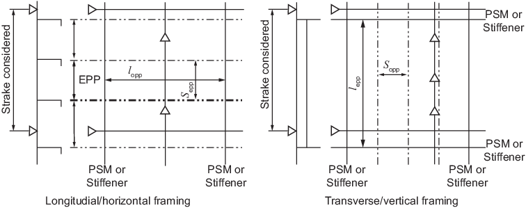
Figure 1.8.8 Elementary plate panel
definition
8.9 Load calculation point for the determination of scantlings of plate panels for hull girder strength
8.9.2 The required thickness of each EPP, with respect to buckling, is to be calculated
based on stresses taken at the mid-length of the EPP measured along the global
x-axis.
|