
Section
3 Bottom structure
3.1 General
3.1.1 Requirements
are given in this Section for both transversely and longitudinally
framed bottoms.
3.1.3 Provision
is to be made for free passage of water, oil and air from all parts
of single or double bottoms, and account being taken of the pumping
rates required.
3.2 Girders
3.2.1 A centreline
girder is to be arranged in ships having a breadth of more than 6
m, and is to be carried as far forward and aft as practicable, and
is to comply with the requirements of Table 5.3.1 Single bottom construction forward
and aft or Table 5.3.2 Double bottom construction forward
and aft.
Table 5.3.1 Single bottom construction forward
and aft
| Item
|
Parameter
|
Requirements
|
| Transverse framing system
|
|
(1) Floors
|
Web depth at centreline
|
|
|
|
Modulus
|
|
Z
|
= |
6 × k × D
1 × s × lf
2 cm3
|
|
|
|
Web
thickness
|
 mm mm
|
|
(2) Centreline girder
|
Web and face plate thickness
|
 mm mm
|
|
|
Face plate
width
|
|
| Longitudinal framing system
|
|
(3) Centreline girder
|
Modulus
|
|
Z
|
= |
8,5 × k × D1 × S ×
le
2 cm3
|
|
|
|
Web
thickness
|

|
|
(4) Bottom transverses
|
Modulus
|
|
Z
|
= |
7 × k × D
1 × S × le
2 cm3
|
|
|
|
Web
thickness
|
|
| Symbols
|
B, D, T, S, s, le,
Z and t are as defined in Pt 3, Ch 5, 1.4 Symbols and definitions 1.4.1
|
D1
|
= |
D, but need not be taken greater than T + 0,4 m for
Zone 3, T + 0,7 m for Zone 2, T + 1,0 m for Zone
1 |
|
df
|
= |
depth of floor or bottom transverse at centreline, in
mm |
|
lf
|
= |
span of the floor, and is normally the breadth of the
ship measured on the top of the floor under consideration, in
metres. If longitudinal bulkheads or equivalent floor supports are
provided an equivalent breadth may be used, but this should be not
less than 0,4B
|
|
w
|
= |
width of face plate of a member, in mm |
|
Note The thickness of plates forming the single bottom
structure is to be not less than 5 mm.
|
Table 5.3.2 Double bottom construction forward
and aft
| Item
|
Parameter
|
Requirements
|
| Transverse and longitudinal framing system
|
|
(1) Centre girder
|
Least depth
|
The greater of:
|
d
f
|
= |
 mm mm |
|
| Thickness
|

|
|
(2) Inner bottom plating
|
Thickness for dry spaces
|
|
| Thickness for tanks
|
The greater of:
|
| (3) Struts
|
Cross-sectional area
|
|
Area
|
= |
2 × le × D1 ×
s cm2
|
|
|
(4) Watertight floors
|
Thickness
|
The thickness of plate floors + 0,5
mm
|
| Transverse framing system
|
|
(5) Plate floors and brackets of bracket floors
|
Thickness
|
 mm mm
|
|
(6) Bottom frames in bracket floors
|
Modulus
|
|
Z
|
= |
6 × k × s × D
1 × le
2 + 1,5 + 0,05L cm3
|
|
|
(7) Reverse frames in bracket floors
|
Modulus
|
|
Z
|
= |
5,5 × k × s × h ×
le
2 + 1,5 + 0,05L cm3
|
|
| Longitudinal framing system
|
|
(8) Plate floors
|
Thickness
|
 mm mm
|
|
(9) Tank top longitudinal
|
Modulus
|
|
Z
|
= |
5,5 × k × s × h ×
le
2 + 1,5 + 0,05L cm3
|
|
| Symbols
|
L, D, T, S, s, t, and Z are
as defined in Pt 3, Ch 5, 1.4 Symbols and definitions 1.4.1
|
D1
|
= |
D, but need not be taken greater than T + 0,4 m or
Zone 3, T + 0,7 m for Zone 2, T + 1,0 m for Zone
1 |
|
df
|
= |
depth of bottom in way of centre girder, in mm |
|
h
|
= |
load head, which is to be taken as the greater of
h
4 or h
5, in metres |
|
h5
|
= |
distance, in metres, from mid point of span to the
deck at side or to a point T + 0,4 m above the baseline,
whichever is the lesser, but is to be taken as not less than 1 m |
|
lb
|
= |
the width of the double bottom, in metres, and is
normally the breadth of the ship. If longitudinal bulkheads or
equivalent support is provided, an equivalent breadth may be used,
but this should be not less than 0,8B
|
|
t1
|
= |
thickness of inner bottom plating or bottom plating,
whichever is the lesser, in mm |
|
Note The thickness of plating forming the double bottom
structure is to be not less than:
5 mm for dry tanks and oil tanks
5,5 mm for water ballast tanks
|
3.3 Single bottom – Transverse framing
3.3.1 Plate floors
are to be fitted at every frame and the scantlings are to comply with
the requirements of Table 5.3.1 Single bottom construction forward
and aft.
The depth of floors at the centreline is to be as required in Table 5.3.1 Single bottom construction forward
and aft, but in ships having considerable
rise of floor towards the ends, the depth of floors may require to
be increased, or the top edge sloped upwards towards the outboard
end, see
Figure 5.3.1 Basic floor arrangements.
If required floors may be cut at the centreline, with the girder web
plate continuous, but the strength of the floors is to be maintained
in way of the centre girder connection. Notwithstanding the requirements
for the fitting of a centreline girder as per Pt 3, Ch 5, 3.2 Girders 3.2.1, suitable arrangements to prevent
tripping of the floors, e.g. riders or tripping brackets, are to be
provided, where the unsupported length of the top edge of the floors
exceeds 20b m;
where
b is the width in metres of the
face plate of the floor.

Figure 5.3.1 Basic floor arrangements
3.3.2 The centre
girder is to have the same depth as the floors.
3.4 Single bottom - Longitudinal framing
3.4.1 Longitudinals
are to be supported by transverses spaced not more than 3,5 m apart.
The transverses are to be supported by a primary centreline girder
or a centreline bulkhead. Tripping brackets connecting transverse
to longitudinal are to be fitted between the centreline girder and
shell at intervals not exceeding 3,5 m. The centreline girder may
be omitted, provided the scantlings of the transverses are suitable
for a span from side to side of the ship, and tripping brackets are
fitted about 3,5 m or 20b m apart, whichever is the lesser,
where b is the width in metres of the face plate of the
transverse. Longitudinals are to be determined from Table 5.4.1 Shell frames and longitudinals
forward and aft. The scantlings of the
centreline girder and bottom transverses are to be determined from Table 5.3.1 Single bottom construction forward
and aft.
3.5 Double bottoms
3.5.2 Plate floors
in a transverse framing system are generally to be fitted at every
frame and the scantlings are to comply with the requirements of Table 5.3.2 Double bottom construction forward
and aft. Vertical stiffeners having
a depth of 80d
f mm are to be fitted to the
floors and spaced not more than 2,5 m apart. The ends of these stiffeners
may be sniped. Alternatively, bracket floors may be fitted, see
Figure 5.3.2 Bracket floor, in which case the spacing
of the plate floors is not to exceed 2,5 m.
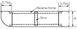
Figure 5.3.2 Bracket floor
3.5.3 Where bracket
floors are fitted the unsupported span of bottom frames and reverse
frames is not to exceed 2,5 m. Struts may be fitted to reduce the
unsupported span. If a strut is fitted at approximately half-span,
the modulus of bottom and reverse frames may be reduced by 50 per
cent. Struts are to comply with the requirements of Table 5.3.2 Double bottom construction forward
and aft. Watertight or plate floors
are to be fitted below or in the vicinity of watertight bulkheads.
3.5.4 Where a
longitudinal framing system is adopted in a double bottom, the scantlings
of tank top longitudinals and plate floors are to comply with the
requirements given in Table 5.3.2 Double bottom construction forward
and aft.
Vertical stiffeners having a depth not less than 50 mm are to be fitted
to the floors at every fourth longitudinal. The plate floors are to
be spaced not more than 3,5 m apart. The centre girder may require
to be stiffened when the height of the bottom is excessive. If a strut
is fitted at approximately half-span the modulus of bottom and tank
top longitudinals may be reduced by 50 per cent. Struts are to comply
with the requirements of Table 5.3.2 Double bottom construction forward
and aft.
3.6 Swim end forward
3.6.1 Where a
longitudinal framing system is adopted, the transverses or floors
supporting longitudinals are to be spaced not more than 2,5 m apart,
and the moduli of longitudinals and transverses are to be increased
by 40 per cent.
3.6.2 Where a
transverse framing system is adopted in swim ends, the modulus of
plate floors is to be increased by 40 per cent.
3.6.3 The draught
for calculation of the structural members may be taken as the actual
draught in way of the respective member.
|