
Section
4 Shell envelope framing
4.1 General
4.1.1 Requirements
are given in this Section for both longitudinal and transverse framing
systems. Where longitudinal framing is adopted in the midship region
it is to be carried forward and aft to at least the fore end and aft
end of the cargo space, including cofferdams in the case of tankers.
4.2 Shell framing
4.2.1 The scantlings
of side frames in the forward and aft regions are to comply with the
requirements given in Table 5.4.1 Shell frames and longitudinals
forward and aft.
Table 5.4.1 Shell frames and longitudinals
forward and aft
|
|
Location
|
Modulus, in cm3
|
 4 4
|
| (1)
|
Frames clear of tanks
|
Z1 = 1,2D1 x k x s
(2,5H2 + 0,03B2 + 6)
|

|
| (2)
|
Frames in way of fuel oil
or water tanks
|
The greater of the following:
|

|
| (a)
|
Z2 = Z1
|
|
| (b)
|
Z2 = as required by Pt 3, Ch 7 Bulkheads
|
|
| (3)
|
Bottom and side shell longitudinals
clear of tanks
|
Z3 = 6 x k x s x h5 x
le
2 + 1,5 + 0,05L
|

|
| (4)
|
Bottom and side shell
longitudinals in way of tanks
|
The greater of the following:
|

|
| (a)
|
Z4 = Z3
|
|
| (b)
|
Z4 = as required by Pt 3, Ch 7 Bulkheads
|
|
| Symbols
|
L, B, D, T, s, Z and I are
as defined in Pt 3, Ch 5, 1.4 Symbols and definitions 1.4.1
|
D1
|
= |
D, but need not be taken greater than T + 0,4 m for
Zone 3, T + 0,7 m for Zone 2, T + 1,0 m for Zone 1 |
|
H
|
= |
vertical framing depth, in metres, from the top edge
of floor or tank top, to the deck at side as shown in Figure 5.4.1 Framing depth, see also Note 1,
but is to be taken as not less than 1,2 m |
|
h5
|
= |
distance, in metres, from mid point of span to the
deck at side or to a point T + 0,4 m above the baseline,
whichever is the lesser, but is to be taken as not less than 1 m |
|
Note
1. Where frames are supported by fully
effective horizontal stringers, these may be considered as decks for
the purpose of determining H.
Note
2. The web depth of frames is to be not
less than 45 mm.
|
4.2.3 Where,
due to the shape of the vessel at the ends, the distance between frames
measured along the shell exceeds the frame spacing, the scantlings
of side shell plating and supporting framing structure are to be based
on the frame spacing as measured along the shell; alternatively intermediate
frames may be fitted or the frame spacing decreased.
4.2.4 The angle
between the frame web and the shell plating is to be not less than
50°. Where this angle varies between 70° and 50° the required
modulus of the frame is to be corrected as per Pt 3, Ch 3, 3.2 Geometric properties of section.
4.2.5 In ships
where the angle between the frame web and the shell plating would
become less than 50°, the transverse framing, together with attached
floors and beams, is to be inclined at an angle to the centreline
of ship so that the frames lie as near normal to the shell plating
as possible.
4.2.6 Where,
due to the curvature or slope of the shell panel, the actual span
of the frame measured along the shell is five per cent more than the
vertical framing depth as per Figure 5.4.1 Framing depth,
the modulus of the frame is to be proportionally increased taking
into consideration the shape of the frame.
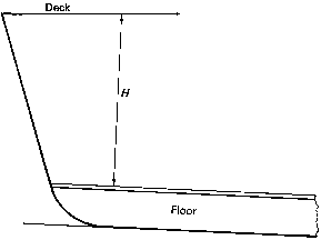
Figure 5.4.1 Framing depth
4.3 Shell longitudinals
4.4 Web frames and side transverses
4.4.1 Web frames
are, in general, to be fitted in a transverse framing system, and
the scantlings are to comply with the requirements of Table 5.4.2 Web frames, side transverses and
stringers forward and aft.
Table 5.4.2 Web frames, side transverses and
stringers forward and aft
| Location
|
Modulus, in
cm3
|
Inertia, in
cm4
|
|
(1) Web frames in a transverse framing system
|
Z = 2,5 ×
k × (2 + n) × s × D
2
3
|
|
|
(2) Side transverses in a longitudinal framing system
|
Z = 7 ×
k × S × D
2
3
|
|
|
(3) Side stringers (fully effective)
|
Z = 8 ×
k × S × h × le
2
|
|
| Symbols
|
D, T, S, s, Z and I are as defined
in Pt 3, Ch 5, 1.4 Symbols and definitions 1.4.1
|
D2
|
= |
D but need not be taken greater than 1,5 × the effective
span of the stiffening member |
|
n
|
= |
number of frame spaces between the web frames or
equivalent structure |
|
h
|
= |
load head, which is to be taken as h
4 or h
5 whichever is the greater, in metres |
|
h5
|
= |
distance, in metres, from mid point of span to the
deck at side or to a point T + 0,4 m for Zone 3, T +
0,7 m for Zone 2, or T + 1,0 m for Zone 1 above the
baseline, whichever is the lesser, with a minimum of 1 m |
|
Note
1. The web depth of side transverses is
to be not less than twice the depth of the slot for the
longitudinal.
Note
2. The web depth of fully effective
stringers is to be not less than twice the depth of the slot for the
frames.
|
4.4.2 The spacing
of the web frames in a transverse framing system should not exceed
10 frame spaces, but the web frames may be omitted, provided the overall
strength is maintained.
4.4.4 Frames
are to be reinforced in way of hatch end beams and deck transverses,
and the section modulus should be not less than 0,4 times the section
modulus of the deck transverse.
4.5 Stringers
4.5.1 On ships
frequently berthing under adverse conditions and where the span of
the frames exceeds 2,5 m, an effective stringer is to be fitted in
a suitable position.
4.6 Stem arrangement for pushing purposes
4.6.1 The structural
arrangements are to be such that the stem is adequately supported
and integrated into the fore peak structure.
4.6.2 The structure
of the stem and the fore peak in way is to be calculated using horizontal
loads P
1 or P
2 on
the stem as shown in Figure 5.4.2 Loads on stem for pushing purposes. The maximum compressive stresses in this structure are
not to exceed 78,4 N/mm2 (800 kg/cm2).
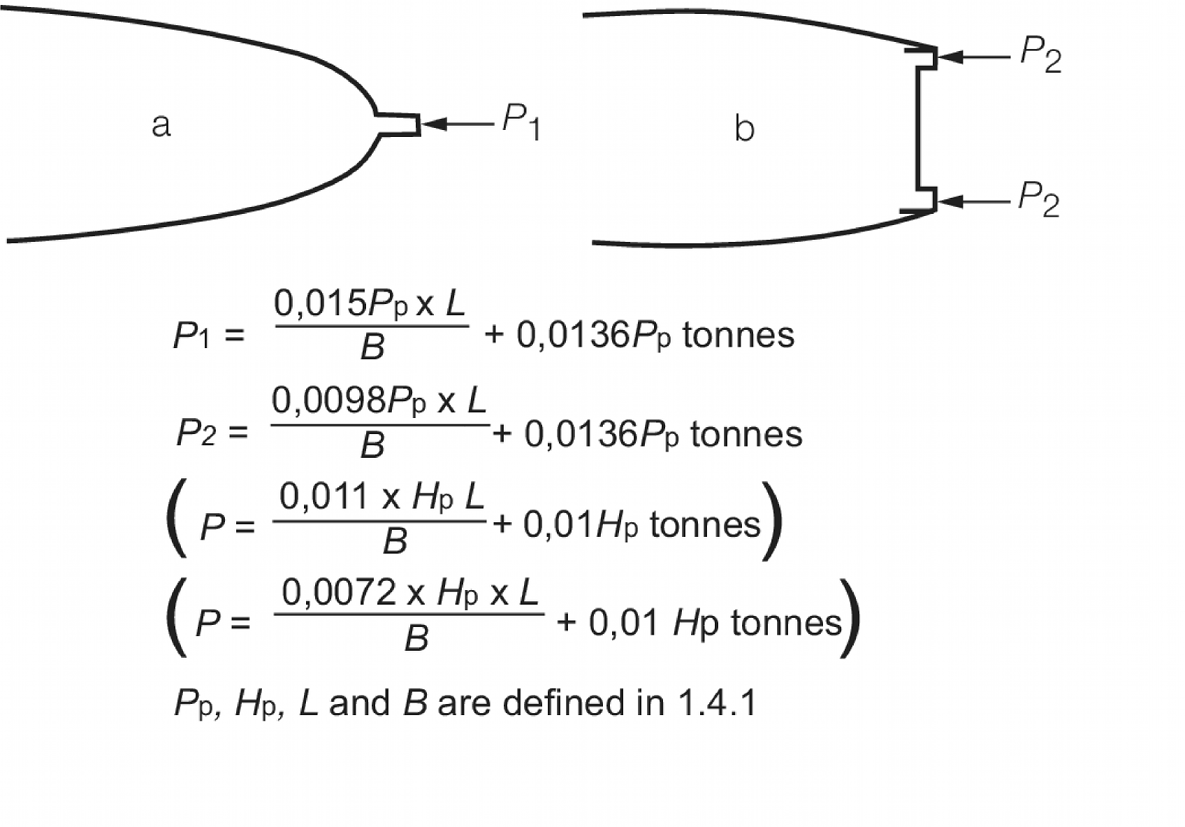
Figure 5.4.2 Loads on stem for pushing purposes
|