
Section
5 Pedestals and foundations
5.1 General
5.1.1 Pedestals and foundations for ship-mounted lifting appliances are
classification items. Pedestals and foundations on offshore installations will be
considered on the same basis as the main support structure, as required by the coastal
state authority or regulatory body.
5.1.2 The loading conditions as defined in Ch 4, 2 Shipboard cranes, Ch 4, 3 Offshore cranes and Ch 4, 4 Submersible handling systems are to be applied in association with the allowable stress levels
contained in this Section. Pedestals and foundations for lifting appliances other than
shipboard cranes, offshore cranes or submersible handling systems will be specially
considered on the basis of this Section, as applicable.
5.1.3 Pedestals,
in general, are to be carried through the deck and satisfactorily
scarphed into the hull or main support structure. Proposals for other
support arrangements will be specially considered. For pedestals not
carried through the decks, it is recommended that suitable gussets
be provided between the pedestal and the deck to distribute loads
to the deck structure.
5.1.4 The pedestal
flange in way of the slew ring bearing is to be designed and be of
a thickness to provide a rigid and level support for the bearing and
bolting. Tolerances and arrangements proposed by the slew ring bearing
manufacturer are to be adhered to.
5.1.5 Where it is
considered necessary to introduce stiffening brackets to support the
flange the spacing of the brackets is to be not greater than that
achieved by positioning them between every second bolt.
5.1.6 This Section covers a pedestal structure which is not part of the hull or
main support structure of the pedestal. The hull or main support structure is to be
designed as per he applicable LR’s Rules for ship types or offshore units. See
also
Ch 1, 1.1 Application 1.1.13 to determine which parts of pedestals and
foundations are covered by which LR requirements.
5.2 Design loads
5.2.1 The pedestal is to be designed with respect to the worst possible
combination of loads as detailed in the applicable parts of Ch 4, 2 Shipboard cranes, Ch 4, 3 Offshore cranes and Ch 4, 4 Submersible handling systems. Pedestals and foundations for lifting appliances other than
shipboard cranes, offshore cranes or submersible handling systems will be specially
considered on the basis of this Section, as applicable.
5.2.2 Stowage arrangements
are to be taken into account when calculating the loads applied to
the pedestal.
5.3 Allowable stresses
5.3.1 The allowable
stress is to be taken as the failure stress of the component concerned
multiplied by stress factor, F
p, which depends
on the load case concerned. The allowable stress is given by the general
expression:
where
5.3.2 The stress factors F
p for steel with  ≤ 0,85 are given in Table 4.5.1 Stress factor,
Fp
. ≤ 0,85 are given in Table 4.5.1 Stress factor,
Fp
.
where
|
σy
|
= |
yield
stress of material |
|
σu
|
= |
ultimate
tensile failure stress of the material. |
5.3.3 For steel where  > 0,85 the allowable stress is to be derived from the following
expression: > 0,85 the allowable stress is to be derived from the following
expression:
The stress factor Fp is defined in Table 4.5.1 Stress factor,
Fp
.
Table 4.5.1 Stress factor,
Fp
| Load case 1
|
Load case 2
|
Load case 3 and 4
|
|
F
p = 0,5
|
F
p = 0,57
|
F
p = 0,64
|
5.3.4 As an alternative to the stress factors Fp as defined in
Table 4.5.1 Stress factor,
Fp
, the stress factors as defined in Table 4.5.2 Alternative stress factor,
Fp
can be applied, provided all of the following
conditions are fulfilled:
-
A fatigue analysis according to a recognised national or
international standard (e.g. F.E.M. 1.001) has satisfactorily been carried out
taking into account operational loads;
-
Overload protection
systems are installed;
-
Beyond a SWL of 160t only engineered lifts are to be carried out;
- The structural integration of the lifting appliance pedestal into the
supporting ship structure is to be verified where required, taking into account the
global hull girder stresses for the corresponding loading condition (still water
loads and wave loading if applicable) and superimposing the stresses resulting from
the lifting appliance operation.
The graphical representation of Table 4.5.2 Alternative stress factor,
Fp
has been provided in Figure 4.5.1 Stress factor,
Fp
.
Table 4.5.2 Alternative stress factor,
Fp
|
|
Load case
1
|
Load case
2
|
Load case
3 and 4
|
| SWL ≤ 40 t
|
F
p = 0,5
|
F
p = 0,57
|
F
p = 0,64
|
| 40 t < SWL < 160 t
|
F
p =  + 0,444 + 0,444
|
F
p =  + 0,510 + 0,510
|
F
p =  + 0,570 + 0,570
|
| SWL ≥ 160 t
|
F
p = 0,67
|
F
p = 0,75
|
F
p = 0,85
|
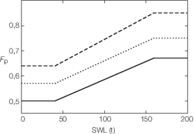
Figure 4.5.1 Stress factor,
Fp
5.3.6 Steels with  > 0,94 are not generally acceptable and will need to be specially
considered. > 0,94 are not generally acceptable and will need to be specially
considered.
5.4 Materials
5.4.3 The grade of steel for pedestals and foundations on offshore installations
or manned submersible handling installations is to comply with the requirements of Ch 4, 3.8 Materials
and/or the requirements of the coastal state authority, as applicable.
5.5 Pedestal flange
5.5.1 The bending stress in a pedestal flange (attached to a cylindrical pedestal)
may be calculated as follows:
where
|
σf
|
= |
bending stress in flange |
|
σtotal
|
= |
total direct stress in pedestal wall below the flange resulting from
overturning moment and vertical force |
|
tf
|
= |
flange thickness |
|
tp
|
= |
pedestal wall thickness below the flange |
|
e
|
= |
distance between the centre of bolt holes and centre of pedestal
wall |
The following recommendations shall be taken into consideration:
- The thickness of the pedestal wall directly attached to the flange is to be
greater than or equal to 1,5 times the minimum theoretical pedestal wall thickness
and shall extend over a length defined by 20 per cent of the outside pedestal wall
diameter.
- The flange thickness is to be greater than or equal to 4,5 times the minimum
theoretical pedestal wall thickness.
- The distance e between the centre of the bolt holes and
centre of the pedestal wall is to be less than or equal to 2 times the bolt hole
diameter.
- The distance between the centre of the bolt holes and the edge of the flange is
to be greater than or equal to 1,5 times the bolt hole diameter.
In case the design of the pedestal is not in line with the above recommendations,
alternative methods for the assessment of the design of the pedestal may need to be
considered.
The allowable stress σa is to be taken as defined in Ch 4, 5.3 Allowable stresses.
The above formula is intended for initial design calculations of the
pedestal flange. In case other effects, e.g. horizontal loading, pre-tension in bolts,
size and amount of holes in the flange, reinforcements, plate bending of the pedestal
wall tp, etc. are considered to have a significant influence on the
pedestal flange design those effects need to be taken into consideration.
Alternative proposals for the calculation of pedestal flanges will be
specially considered.
5.5.2 It is recommended
that pedestal flanges be made of forged material. Where rolled plates
are applied for pedestal flanges in place of forged material, recognised
National or International Standards are to be used to assess the requirement
for Z-grade material with the results of the assessment included in
the design submission.
|