
Section
2 Fittings
2.1 Gooseneck and derrick heel assemblies
2.1.1 The safe working
load of the gooseneck and derrick heel assembly is to be taken as
the least of the values determined separately for the gooseneck pin,
the derrick heel lugs and the derrick heel crosspin. Standard dimensions
for these items and for the gooseneck bearing bracket, with corresponding
safe working loads, are given in Table 8.2.1 Dimensions of gooseneck
pins and the items are illustrated in Figure 8.2.1 Gooseneck pins.
Table 8.2.1 Dimensions of gooseneck
pins
| Boom
axial thrust, in tonnes
|
Straight pins
|
Cranked pins
|
|
|
|
|
|
d
1
|
l1
|
d
1
|
l1
|
e
|
d
2
|
r
|
t
|
| 1,6
|
50
|
60
|
—
|
—
|
—
|
24
|
25
|
26
|
| 2,0
|
50
|
60
|
—
|
—
|
—
|
26
|
25
|
28
|
| 2,5
|
60
|
60
|
55
|
60
|
35
|
29
|
30
|
30
|
| 3,2
|
70
|
85
|
60
|
65
|
38
|
32
|
35
|
33
|
| 5,0
|
70
|
70
|
65
|
70
|
40
|
35
|
35
|
36
|
| 5,0
|
80
|
85
|
70
|
80
|
46
|
41
|
40
|
40
|
| 6,3
|
90
|
100
|
80
|
85
|
49
|
44
|
45
|
45
|
| 8,0
|
100
|
105
|
90
|
90
|
52
|
47
|
50
|
50
|
| 10,0
|
110
|
120
|
100
|
100
|
58
|
54
|
55
|
57
|
| 12,5
|
120
|
125
|
110
|
105
|
61
|
58
|
60
|
64
|
| 16,0
|
140
|
150
|
120
|
110
|
64
|
67
|
70
|
73
|
| 20,0
|
155
|
170
|
130
|
115
|
67
|
75
|
75
|
82
|
| 25,0
|
170
|
200
|
140
|
125
|
72
|
79
|
80
|
92
|
| 32,0
|
190
|
210
|
155
|
140
|
78
|
83
|
85
|
102
|
| 40,0
|
190
|
220
|
170
|
155
|
85
|
93
|
95
|
112
|
| 50,0
|
200
|
220
|
—
|
—
|
—
|
103
|
100
|
124
|
| 63,0
|
225
|
245
|
—
|
—
|
—
|
113
|
113
|
140
|
| 80,0
|
250
|
275
|
—
|
—
|
—
|
129
|
125
|
150
|
| 100,0
|
275
|
290
|
—
|
—
|
—
|
144
|
138
|
160
|
|
|
Table 8.2.2 Dimensions of derrick heel
assemblies
| Boom axial thrust, in
tonnes
|
a
|
b
|
c
|
r
|
t
|
d
2
|
d
crosspin
|
| 1,6
|
32
|
80
|
28
|
25
|
16
|
24
|
22
|
| 2,0
|
35
|
90
|
30
|
28
|
16
|
26
|
24
|
| 2,5
|
45
|
107
|
32
|
30
|
22
|
29
|
27
|
| 3,2
|
50
|
112
|
35
|
32
|
22
|
32
|
30
|
| 4,0
|
50
|
120
|
38
|
35
|
25
|
35
|
33
|
| 5,0
|
55
|
135
|
42
|
42
|
25
|
41
|
39
|
| 6,3
|
60
|
145
|
47
|
45
|
32
|
44
|
42
|
| 8,0
|
65
|
153
|
53
|
48
|
32
|
47
|
45
|
| 10,0
|
70
|
173
|
60
|
55
|
40
|
54
|
52
|
| 12,5
|
75
|
188
|
67
|
60
|
40
|
58
|
56
|
| 16,0
|
85
|
208
|
76
|
68
|
45
|
67
|
64
|
| 20,0
|
95
|
235
|
85
|
75
|
50
|
75
|
72
|
| 25,0
|
100
|
260
|
95
|
80
|
60
|
79
|
76
|
| 32,0
|
105
|
270
|
105
|
85
|
70
|
83
|
80
|
| 40,0
|
115
|
300
|
115
|
95
|
70
|
93
|
90
|
| 50,0
|
125
|
325
|
127
|
105
|
80
|
103
|
100
|
| 63,0
|
135
|
340
|
144
|
115
|
80
|
113
|
110
|
| 80,0
|
160
|
350
|
154
|
130
|
100
|
129
|
125
|
| 100,0
|
175
|
370
|
164
|
145
|
100
|
144
|
140
|
Note
2. Values of a and b may be
adjusted for other forms of rib stiffening.
|
Table 8.2.3 Dimensions of gooseneck bearing
brackets
Gooseneck pin
diameter, d
1
|
a
|
b
|
c
|
d
3
|
t
1
|
t
2
|
| 50
|
95
|
45
|
70
|
85
|
12
|
10
|
| 55
|
95
|
45
|
80
|
90
|
12
|
10
|
| 60
|
95
|
50
|
90
|
100
|
12
|
10
|
| 65
|
120
|
50
|
100
|
110
|
12
|
10
|
| 70
|
120
|
60
|
115
|
120
|
12
|
10
|
| 80
|
140
|
60
|
130
|
130
|
12
|
10
|
| 90
|
140
|
70
|
145
|
140
|
12
|
10
|
| 100
|
175
|
70
|
160
|
160
|
15
|
10
|
| 110
|
175
|
80
|
175
|
170
|
20
|
12
|
| 120
|
215
|
80
|
190
|
190
|
20
|
12
|
| 130
|
215
|
90
|
205
|
200
|
22
|
12
|
| 140
|
215
|
90
|
225
|
210
|
25
|
12
|
| 155
|
235
|
100
|
235
|
230
|
30
|
15
|
| 160
|
235
|
100
|
240
|
235
|
30
|
15
|
| 170
|
235
|
100
|
250
|
250
|
30
|
15
|
| 180
|
235
|
100
|
270
|
260
|
30
|
15
|
| 190
|
255
|
110
|
285
|
280
|
33
|
18
|
| 200
|
255
|
110
|
300
|
290
|
35
|
18
|
| 225
|
255
|
120
|
315
|
325
|
40
|
20
|
| 250
|
275
|
130
|
330
|
360
|
40
|
20
|
| 275
|
275
|
140
|
345
|
395
|
40
|
20
|
Note
2. The width of bracket at the mast
(dimension w in Figure 8.2.3 Gooseneck bearing) is to be not less than 0,67
times the diameter of the mast at that point.
|
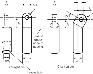
Figure 8.2.1 Gooseneck pins
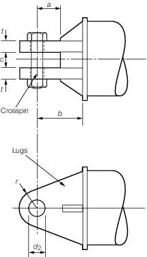
Figure 8.2.2 Derrick heel assembly
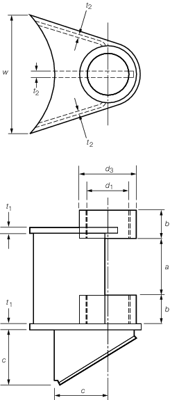
Figure 8.2.3 Gooseneck bearing
2.1.3 Where arrangements
other than those covered by the Tables or by recognised Standards
are proposed, the dimensions of the components of the assembly are
to be such that the stresses given in Table 8.2.4 Stresses in gooseneck and
derrick are not exceeded.
Table 8.2.4 Stresses in gooseneck and
derrick
| Item
|
Boom axial thrust, T, in tonnes
|
|
|
T ≤ 25
N/mm2
|
25 < T ≤
50
N/mm2
|
50 < T
N/mm2
|
| Gooseneck pin:
|
|
|
|
|
|
Bending plus direct stress
|
90
|
40 + 2T
|
140
|
|
|
Bearing pressure
|
20 + 0,5T
|
20 + 0,5T
|
45
|
|
|
|
|
|
|
| Derrick heel crosspin:
|
|
|
|
|
|
Shear stress
|
25 +
0,4T
|
35
|
35
|
|
|
Bending plus shear stress
|
90 + T
|
90 + T
|
140
|
|
|
Bearing pressure
|
20 + 0,5T
|
20 + 0,5T
|
45
|
|
|
|
|
|
|
| Gooseneck pin collar:
|
|
|
|
|
|
Horizontal bearing
pressure
|
10 N/mm2
|
|
|
Minimum diameter
|
1,15d
1 mm
|
|
|
|
|
|
|
| Bearing bracket
|
Total stress in any part is not to exceed 0,45σy
|
2.1.4 Where a gooseneck
pin is supported by two bearings, the diameter of the pin in way of
the lower bearing may be reduced to 0,6d
1,
provided the bearings are spaced such that (a + b)
is greater than 3,0d
1, see
Figure 8.2.3 Gooseneck bearing for illustration of these terms.
Proposals for a greater reduction on large gooseneck pins will be
specially considered.
2.2 Swivel bearing assemblies
2.2.1 The safe working
load of the assembly is to be taken as the least of the values determined
separately for the individual components. Standard dimensions for
the trunnion, pin and bearing bracket with corresponding safe working
loads are given in Table 8.2.5 Dimensions of swivels and Table 8.2.6 Dimensions of swivel bearing
brackets and the items are illustrated
in Figure 8.2.4 Swivel bearing assemblies.
Table 8.2.5 Dimensions of swivels
| SWL, in tonnes
|
a
|
b
|
d
1
|
d
2
|
d
3
|
r
1
|
t
1
|
d
pin
|
| 2,0
|
75
|
90
|
34
|
65
|
25
|
25
|
22
|
32
|
| 4,0
|
95
|
110
|
42
|
80
|
33
|
33
|
30
|
40
|
| 6,3
|
110
|
130
|
47
|
90
|
42
|
43
|
40
|
45
|
| 8,0
|
120
|
150
|
52
|
100
|
48
|
48
|
45
|
50
|
| 10,0
|
130
|
170
|
57
|
110
|
52
|
55
|
50
|
55
|
| 12,5
|
140
|
190
|
62
|
120
|
56
|
60
|
55
|
60
|
| 16,0
|
150
|
215
|
68
|
130
|
65
|
65
|
60
|
65
|
| 20,0
|
170
|
240
|
78
|
150
|
74
|
70
|
65
|
75
|
| 25,0
|
180
|
270
|
83
|
160
|
78
|
75
|
70
|
80
|
| 32,0
|
190
|
300
|
93
|
180
|
86
|
85
|
80
|
90
|
| 40,0
|
210
|
330
|
103
|
200
|
96
|
95
|
90
|
100
|
| 50,0
|
235
|
380
|
113
|
220
|
106
|
105
|
100
|
110
|
| 63,0
|
260
|
410
|
123
|
240
|
116
|
115
|
110
|
120
|
| 80,0
|
295
|
480
|
134
|
260
|
131
|
135
|
125
|
130
|
| 100,0
|
330
|
540
|
144
|
280
|
146
|
148
|
140
|
140
|
Note
2. SWL is the required SWL of the bearing
assembly.
|
Table 8.2.6 Dimensions of swivel bearing
brackets
| SWL, in tonnes
|
c
|
d
1
|
e
|
g
|
h
|
t
2
|
t
3
|
r
2
|
| 2,0
|
75
|
34
|
75
|
140
|
95
|
21
|
10
|
35
|
| 4,0
|
95
|
42
|
80
|
160
|
115
|
15
|
10
|
43
|
| 6,3
|
115
|
47
|
90
|
180
|
135
|
20
|
10
|
48
|
| 8,0
|
140
|
52
|
110
|
200
|
155
|
25
|
10
|
55
|
| 10,0
|
160
|
57
|
125
|
230
|
175
|
25
|
12
|
60
|
| 12,5
|
175
|
62
|
140
|
260
|
195
|
30
|
12
|
65
|
| 16,0
|
190
|
68
|
150
|
290
|
223
|
30
|
12
|
70
|
| 20,0
|
205
|
78
|
160
|
320
|
248
|
35
|
15
|
80
|
| 25,0
|
220
|
83
|
180
|
240
|
278
|
35
|
15
|
85
|
| 32,0
|
220
|
93
|
190
|
370
|
308
|
40
|
15
|
95
|
| 40,0
|
245
|
103
|
190
|
410
|
338
|
45
|
15
|
105
|
| 50,0
|
270
|
113
|
210
|
450
|
388
|
45
|
18
|
115
|
| 63,0
|
300
|
123
|
230
|
500
|
420
|
50
|
20
|
125
|
| 80,0
|
335
|
134
|
260
|
560
|
490
|
50
|
20
|
135
|
| 100,0
|
375
|
144
|
300
|
630
|
550
|
55
|
20
|
148
|
Note
2. SWL is the required SWL of the bearing
assembly.
|

Figure 8.2.4 Swivel bearing assemblies
2.2.3 Where arrangements
other than those covered by the Tables or by recognised Standards
are proposed, the dimensions of the components of the assembly are
to be such that the stresses given in Table 8.2.7 Stresses in swivel bearing
assemblies are not exceeded.
Table 8.2.7 Stresses in swivel bearing
assemblies
| Item
|
Safe working load, in tonnes
|
|
|
SWL ≤ 25,
N/mm2
|
25 <
SWL,
N/mm2
|
| Swivel
pin:
|
|
|
|
|
Shear stress
|
25 + 0,4 SWL
|
35
|
|
|
Bearing pressure
|
40 + 0,6 SWL
|
55
|
|
|
|
|
|
| Trunnion
eyeplate:
|
|
|
|
|
Shear pullout at hole
|
50
|
|
|
|
Bearing bracket
|
Total
stress on any part is not to exceed 0,45σy
|
Note Safe working load is the required SWL of the bearing
assembly
|
2.3 Fixed eyeplates
2.3.1 Fixed eyeplates
at the derrick boom head are generally to be in accordance with the
dimensions given in Table 8.2.8 Dimensions of fixed eyeplates at
the derrick boom head
Table 8.2.8 Dimensions of fixed eyeplates at
the derrick boom head
| SWL, in tonnes
|
Oval
eye
a
|
Round
eye
b
|
e
1
|
t
1
|
d
|
r
2
|
e
2
|
t
2
|
| 2,0
|
50
|
27
|
50
|
25
|
25
|
25
|
40
|
22
|
| 2,5
|
55
|
29
|
54
|
25
|
27
|
28
|
40
|
25
|
| 3,2
|
66
|
33
|
57
|
30
|
30
|
30
|
45
|
28
|
| 4,0
|
77
|
36
|
65
|
35
|
33
|
33
|
50
|
30
|
| 5,0
|
87
|
41
|
70
|
40
|
39
|
38
|
55
|
35
|
| 6,3
|
91
|
45
|
75
|
40
|
42
|
43
|
60
|
40
|
| 8,0
|
101
|
51
|
80
|
50
|
48
|
48
|
70
|
45
|
| 10,0
|
117
|
56
|
90
|
50
|
52
|
55
|
75
|
50
|
| 12,5
|
128
|
61
|
100
|
60
|
56
|
60
|
80
|
55
|
| 16,0
|
145
|
67
|
115
|
60
|
65
|
65
|
85
|
60
|
| 20,0
|
157
|
73
|
125
|
70
|
74
|
70
|
95
|
65
|
| 25,0
|
170
|
80
|
135
|
80
|
78
|
75
|
100
|
70
|
| 32,0
|
194
|
88
|
150
|
90
|
86
|
85
|
110
|
80
|
| 40,0
|
220
|
98
|
170
|
100
|
96
|
95
|
120
|
90
|
Note
2. The dimensions e
1 and e
2 are to be measured from the outside surface of the
derrick boom tube, or the outside surface of the doubling plate, if
fitted.
|
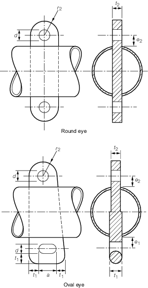
Figure 8.2.5 Fixed eyeplates at the derrick
boom head
2.3.2 The dimensional
details of the fittings may differ at opposite ends depending on the
loads to be carried. Where the fitting is made continuous and of the
larger thickness required by the Table, care is to be taken to ensure
that this thickness is suitable for the proposed shackle or other
attachment to the eyeplate.
2.3.3 It is highlighted
that an increase in the dimension e1 or e2 will result in an increased
bending moment on the derrick boom and this may result in increased
scantlings.
2.3.4 Fixed eyeplates
attached to the ship’s structure for use with the cargo gear
are to have dimensions generally in accordance with Table 8.2.9 Dimensions of eyeplates at
ship's. Attention is to be given
to the stresses which may arise from applied forces not in the plane
of the eyeplate. Where the dimensions of the eyeplate differ from
the Table values, the safe working load may be taken as:
where
dimensions a, b, d and t are illustrated in Figure 8.2.6 Fixed eyeplate at the ship's
structure.
Where the cross-section of the eyeplate
varies, the minimum value of (d x t) is
to be used for the calculation.
Table 8.2.9 Dimensions of eyeplates at
ship's
| SWL, in tonnes
|
a
|
b
|
d
|
t
|
| 1,0
|
35
|
22
|
16
|
16
|
| 1,6
|
42
|
24
|
20
|
20
|
| 2,0
|
50
|
27
|
25
|
25
|
| 2,5
|
55
|
29
|
25
|
25
|
| 3,2
|
66
|
33
|
30
|
30
|
| 4,0
|
77
|
36
|
35
|
35
|
| 5,0
|
87
|
41
|
40
|
40
|
| 6,3
|
91
|
45
|
40
|
40
|
| 8,0
|
101
|
51
|
50
|
50
|
| 10,0
|
117
|
56
|
50
|
50
|
| 12,5
|
128
|
61
|
60
|
60
|
| 16,0
|
145
|
67
|
60
|
60
|
| 20,0
|
157
|
73
|
70
|
70
|
| 25,0
|
170
|
80
|
80
|
80
|
| 32,0
|
194
|
88
|
90
|
90
|
| 40,0
|
220
|
98
|
100
|
100
|
| 50,0
|
240
|
108
|
110
|
110
|
|
|

Figure 8.2.6 Fixed eyeplate at the ship's
structure
2.3.5 Adequate support is to be provided by the ship structure in way of the
eyeplate. Arrangements to give effective spread of the load into the surrounding
structure may be required, see also
Ch 2, 8.9 Deck eyeplates.
2.4 Built-in sheaves
2.4.1 Where a built-in
sheave is fitted in the derrick boom, the diameter of the sheave is
to be not less than that required for the rope nor less than 1,2 times
the derrick boom diameter at that point. The material, construction
and design of the sheave, sheave pin and supports are to be in accordance
with Ch 8, 3 Blocks.
|