
Section
8 Welding
8.1 General
8.1.1 The plans
to be submitted for approval are to indicate clearly details of the
welded connections of main structural members, including the type
and size of welds. This requirement includes welded connections to
steel castings. The information to be submitted should include the
following:
-
Whether weld sizes
given are throat thicknesses or leg lengths.
-
Grades and thicknesses
of materials to be welded.
-
Location, types
of joints and angles of abutting members.
-
Reference to welding
procedures to be used.
-
Sequence of welding
of assemblies and joining up of assemblies, see
Pt 2, Ch 1, 8.4 Welding of primary and secondary member end connections.
8.1.2 Unless
otherwise indicated, all welding is to be in accordance with the requirements
of Ch 13 Requirements for Welded Construction of the Rules for
the Manufacture, Testing and Certification of Material (hereinafter
referred to as the Rules for Materials).
8.2 Fillet welds
8.2.1 The throat
thickness of fillet welds is to be determined from:
where
|
s
|
= |
the
length, in mm, of correctly proportioned weld fillet, clear of end
craters, and is to be not less than 75 mm |
|
d
|
= |
the
distance between start positions of successive weld fillets, in mm |
|
t
p
|
= |
plate thickness, on which weld fillet size is based, in mm, see
also
Figure 1.8.1 Weld types
|
Weld factors are given in Table 1.8.1 Details of various fillet weld
connections.

Figure 1.8.1 Weld types
8.2.2 Where
double continuous fillet welding is proposed, the throat thickness
is to be determined taking equal to 1,0. The leg length of the weld is to be not
less than equal to 1,0. The leg length of the weld is to be not
less than  the specified throat thickness. the specified throat thickness.
8.2.3 The plate
thickness, t
p, to be used in the above calculation
is, generally, to be that of the thinner of the two parts being joined.
Where the difference in thickness is considerable, the size of fillet
will be considered.
8.2.4 Where
the thickness of the abutting member of the connection (e.g. the web
of a stiffener) is greater than 15 mm and exceeds the thickness of
the table member (e.g. plating), the welding is to be double continuous
and the throat thickness of the weld is to be not less than the greatest
of the following:
-
0,21 x thickness
of the table member;
-
0,21 (0,27 in tanks)
× half the thickness of the abutting member;
-
as required by Item
3 in Table 1.8.3 Throat thickness limits.
Table 1.8.1 Details of various fillet weld
connections
| Item
|
Weld factor
|
Remarks
|
| Bottom and side frames and transverse
to shell
|
0,13
|
continuous in way of beam
|
| Bottom and
side longitudinals to shell
|
0,13
|
|
| Bottom and
side longitudinals of flat bar or plate type to shell
|
0,25
|
|
| Longitudinal and
transverse watertight and oiltight bulkhead boundaries
|
0,39
|
at
bottom
|
| 0,34
|
at deck and
side
|
| Stiffeners
on watertight and oiltight bulkheads
|
0,13
|
|
| Longitudinal and transverse non-watertight bulkhead boundaries
|
0,13
|
|
| Stiffeners
on non-watertight bulkheads
|
0,10
|
|
| Pontoon girders to
shell
|
0,27
|
in way of
end brackets
|
| 0,27
|
clear of end
brackets
|
| Pontoon
girders to girder brackets
|
0,21
|
|
| Girder webs
to face bars
|
0,13
|
|
|
|
|
|
| Strength
deck plating or shell
|
-
|
see
Table 1.8.2 Weld connection of strength deck
plating to sheerstrake
|
| Safety deck
plating to shell
|
0,21
|
continuous
|
| Beams and
longitudinals at crown of tanks to deck
|
0,13
|
|
| Beams and
longitudinals to deck
|
0,10
|
|
| Deck longitudinals of
flat bar or plate type to deck plating
|
0,25
|
see
Pt 2, Ch 1, 8.2 Fillet welds
|
| continuous
|
|
|
|
|
|
| Deck
transverses to plating
|
0,21
|
continuous
in way of end brackets
|
|
|
|
|
| Deck
transverses to end brackets
|
0,21
|
generally
continuous
|
| Webs of
transverses to face bars
|
0,13
|
face bar
area in excess of 39 cm2
|
|
|
|
|
| Ventilator
coamings and air pipes to deck plating
|
0,34
|
| Pillars
built of rolled sections of plates
|
0,10
|
8.2.6 Continuous
welding is to be adopted in the following locations, and may be used
elsewhere if desired:
-
Boundaries of weathertight
decks and erections, including hatch coamings, companionways and other
openings.
-
Boundaries of tanks
and watertight compartments.
-
All lap welds in
tanks.
-
Primary and secondary
members to bottom shell.
-
Primary and secondary
members to plating in way of end connections, and end brackets to
plating in the case of lap connections.
-
Where Pt 2, Ch 1, 8.2 Fillet welds 8.2.4 applies.
-
Other connections
or attachments, where considered necessary, and in particular the
attachment of minor fittings to higher tensile steel plating.
-
Fillet welds where
higher tensile steel is used.
8.2.7 Where
structural members pass through the boundary of a tank, and leakage
into the adjacent space could be hazardous or undesirable, full penetration
welding is to be adopted for the members for at least 150 mm on each
side of the boundary. Alternatively, a small scallop of suitable shape
may be cut in the member close to the boundary outside the compartment,
and carefully welded all round.
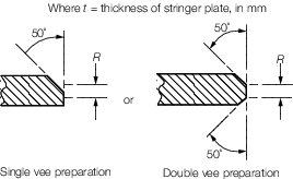
Table 1.8.2 Weld connection of strength deck
plating to sheerstrake
| Item
|
Stringer plate
thickness
|
Weld type
|
| 1
|
t ≤ 15
|
Double continuous fillet weld with a
weld factor of 0,44
|
| 2
|
15 <
t ≤ 20
|
Single vee
preparation to provide included angle of 50º with root R ≤ 1/3
t in conjunction with a continuous fillet weld having a weld
factor of 0,39 or Double vee preparation to provide included angles of 50º
with root R ≤ 1/3 t
|
| 3
|
t > 20
|
Double vee preparation to provide
included angles of 50º with root R ≤ 1/3 t but not to exceed
10 mm
|
|
Note
1. Welding procedure, including joint
preparation, is to be specified. Procedure is to be qualified and
approved for individual Builders.
Note
2. For thickness t in excess of 30
mm, the stringer plate may be bevelled to achieve a reduced thickness
at the weld connection. The width of bevel is, in general, to be not
less than twice the thickness of stringer plate and the reduced
thickness, in general, to be not less than 0,65 times the thickness of
stringer plate or 20 mm, whichever is the greater.
Note
3. Alternative connections will be
considered.
|
8.3 Welding of primary structure
8.3.1 The weld
connection to shell, deck or bulkhead is to take account of the material
lost in the notch where longitudinals or stiffeners pass through the
member.
8.3.2 Where
the width of notch exceeds 15 per cent of the stiffener spacing, the
weld factor is to be multiplied by:
8.3.3 Where
direct calculation procedures have been adopted, the weld factors
for the 0,2 x overall length at the ends of the members will be considered
in relation to the calculated loads.
8.3.4 The throat
thickness limits given in Table 1.8.3 Throat thickness limits are
to be complied with.
Table 1.8.3 Throat thickness limits
| Item
|
Throat thickness, in mm
|
| Minimum
|
Maximum
|
|
(1) Double continuous welding
|
0,21t
p
|
0,44t
p
|
|
(2) Intermittent welding
|
027t
p
|
0,44t
p or 4,5
|
|
(3) All welds, overriding minimum:
|
|
|
|
(a) Plate thickness t
p ≤ 7,5 mm
|
|
|
|
Hand or automatic welding
|
3,0
|
-
|
|
Automatic deep penetration welding
|
3,0
|
-
|
|
(b) Plate thickness t
p > 7,5 mm
|
|
|
|
Hand or automatic welding
|
3,25
|
-
|
|
Automatic deep penetration welding
|
3,0
|
-
|
Note
1. In all cases, the limiting value is to
be taken as the greatest of the applicable values given above.
Note
2. Where t
p exceeds 25 mm, the limiting values may be calculated
using a notional thickness equal to 0,5 (t
p + 25) mm.
Note
3. The maximum throat thicknesses shown
are intended only as a design limit for the approval of fillet welded
joints. Any welding in excess of these limits is to be to the
Surveyor’s satisfaction.
|
8.4 Welding of primary and secondary member end connections
8.4.1 Welding
of end connections of primary members is to be such that the area
of welding is not less than the cross-sectional area of the member,
and the weld factor is to be not less than 0,34 in tanks or 0,27 elsewhere.
8.4.3 The area
of weld, A
w, is to be applied to each arm
of the bracket or lapped connection.
8.4.4 Where
a longitudinal strength member is cut at a primary support and the
continuity of strength is provided by brackets, the area of weld is
to be not less than the cross-sectional area of the member.
8.4.6 The throat
thickness limits given in Table 1.8.3 Throat thickness limits are
to be complied with.
Table 1.8.4 Primary and secondary member end
connection welds
| Connection
|
Weld area, A
w, in cm2
|
Weld factor
|
|
(1) Stiffener welded direct to plating
|
0,25A
s or 6,5 cm2 whichever is the greater
|
0,34
|
|
(2) Bracketless connection of stiffeners or stiffener lapped
to bracket or bracket lapped to stiffener:
|
|
|
|
(a) in dry space
|
1,2
|
0,27
|
|
(b) in tank
|
1,4
|
0,34
|
|
(c) main frame to tank side bracket in 0,15L forward
|
as (a) or (b)
|
0,34
|
|
|
|
|
|
(3) Bracket welded to face of stiffener and bracket
connection to plating
|
-
|
0,34
|
|
|
|
|
|
(4) Stiffener to plating for 0,1 x span at ends, or in way of
end bracket if that be greater
|
-
|
0,34
|
| Symbols
|
|
A
s
|
= |
cross-sectional area of the stiffener, in
cm2
|
|
A
w
|
= |
the area of weld, in cm2, and is
calculated as total length of weld, in cm, x throat thickness, in
cm |
|
Z
|
= |
the section modulus, in cm3, of the
stiffener on which the scantlings of the bracket are based |
|
|
|
8.5 Defined practices and welding sequence
8.5.1 Welding
is to be conducted in accordance with the requirements specified in
Ch 13,1 and 2 of the Rules for Materials
8.6 Welding consumables and equipment
8.6.1 Welding
consumables used and associated equipment are to be in accordance
with the requirements specified in Ch 13,1.8 and 2.2 of the Rules
for Materials.
8.7 Inspection of welds
8.7.2 The location
and number of welds to be examined by non-destructive examination
is to be agreed between the Builder and the Surveyor. Recommended
locations and the number of non-destructive examinations are shown
in Table 1.8.5 Inspection of welds
8.7.3 For docks
specially designed to operate in low temperature ambient conditions
such as those prevailing in Arctic areas, the extent of non-destructive
examination will be specially considered.
8.7.4 For structural
details, reference should be made to Pt 3, Ch 10 Welding and Structural Details of the Rules for Ships.
Table 1.8.5 Inspection of welds
Material
Class
See Note 1
|
Recommended locations and number of NDE to be applied
|
|
|
Intersections of butts
and seams of fabrication and erection welds
|
Butts and seams
See Note 2
|
| V &
IV
|
Minimum – One in
two
|
Minimum – One for each
10 m of weld length
|
| III
|
Minimum – One in
three
|
Minimum – One for each
20 m of weld length
|
| II
|
Minimum – One in
four
|
Minimum – One for each
30 m of weld length
|
| I
|
At selected locations
See Note 3
|
At selected locations
See Note 3
|
|
|
Butt
welds of hull envelope longitudinals are to be examined as follows:
|
|
= |
Within 0,4L amidships – one in ten
|
|
|
= |
Outside 0,4L amidships – one in twenty
|
|
Note
2. These are in addition to locations
selected at intersection of butts and seams of fabrication and
erection welds.
Note
3. Additional locations are to be
selected in the forward region.
Note
4. Selected NDE locations are to be
evenly distributed.
Note
5. Where radiographic examination is
carried out at weld intersections, the length of the film is to be in
the direction of the butt.
Note
6. Where defects are observed at or near
the ends of radiographs, additional radiography is to be carried out
to determine the full extent.
|
|