
Section
10 Miscellaneous openings
10.1 General
10.2 Openings in main vehicle deck
10.2.1 Where
the main vehicle deck is enclosed, all companionways and openings
in the deck which lead to spaces below are generally to be protected
by steel doors or hatch covers. Approved fire doors may be accepted
in lieu of steel doors. The sills or coamings are to be not less than
230 mm above the main vehicle deck, with the exception of those leading
to machinery spaces which are to have sills or coamings not less than
380 mm. Exceptionally, when such openings are to be kept closed at
sea, sills or coamings may be reduced in height, provided that the
sealing arrangements are adequate. In such cases, the doors or hatch
covers are to be secured weathertight by gaskets and a sufficient
number of clamping devices. Such items as portable plates in the main
vehicle deck arranged for the removal of machinery parts, etc. may
be arranged flush with the deck, provided they are secured by gaskets
and closely spaced bolts at a pitch not exceeding five diameters.
10.2.2 Scuppers
from vehicle or cargo spaces above the bulkhead deck fitted with an
approved fixed pressure water spray fire-extinguishing system are
to be led directly overboard and are to be fitted with means of preventing
water from passing inboard in accordance with Pt 3, Ch 12, 4.2 Closing appliances.
10.2.3 Inboard
draining scuppers do not require valves but are to be led to suitable
drain tanks (not engine room or hold bilges) and the capacity of the
tanks is to be sufficient to hold approximately 20 minutes of drenching
water. The arrangements for emptying these tanks are to be approved
and suitable high level alarms provided.
10.2.4 A
drainage system is to be arranged in the area between bow door and
ramp, or where no ramp is fitted, between the bow door and inner door.
The system is to be equipped with an audible and visual alarm function
to the navigation bridge being set off when the water levels in these
areas exceed 0,5 m or the high water level alarm, whichever is the
lesser.
10.2.5 The
drainage arrangement for each area is to have sufficient capacity
to prevent accumulation of water in case of leakage. Scuppers are
to be provided on both sides of the ship with a diameter not less
than 50 mm and in accordance with Pt 3, Ch 12, 4 Scuppers and sanitary discharges. Alternatively, a bilge suction should be provided.
10.2.7 Air
pipes from cofferdams or void spaces may terminate in the enclosed
'tween deck space on the main vehicle deck provided the space is adequately
ventilated and the air pipes are provided with weathertight closing
appliances.
10.2.8 Between
the bow door and the inner door a television surveillance system is
to be fitted with a monitor on the navigation bridge and in the engine
control room. The system must monitor the position of doors and a
sufficient number of their securing devices. Special consideration
is to be given for lighting and contrasting colour of objects under
surveillance, see also
Pt 4, Ch 2, 8.5 Arrangements for the closing, securing and supporting of doors 8.5.7.
10.3 Strength assessment of windows in large passenger ships
10.3.1 On
windows in the second tier and higher above the freeboard deck, a
glazing equivalent may be fitted in lieu of deadlights/storm covers.
The thicknesses and arrangements are to be acceptable to the National
Authority with whom the ship is registered and/or by the Administration
within whose territorial jurisdiction the ship is intended to operate.
For arrangements of glazing acceptable to LR, see
Table 2.10.1 Acceptable arrangements of glazing
in lieu of portable storm covers/deadlights. Alternative arrangement
of glazing in lieu of deadlights/storm covers may be accepted provided
details are submitted for consideration.
10.3.4 Toughened safety glass of laminated construction will also be accepted,
provided the requirements of Pt 3, Ch 11, 6.5 Side scuttles, windows and skylights 6.5.29 are complied with.
Table 2.10.1 Acceptable arrangements of glazing
in lieu of portable storm covers/deadlights
Table 2.10.2 Design pressure,
Hd, on windows
| Window location
|
Design pressure head
H
d in metres
|
| Between the design waterline and a
point Z
1,5 m above the waterline
|
Per BS MA 25: 1973
|
| Between a
point Z
1,5 m above the waterline and the deck immediately above (at
Z
d1,5)
|
1,5
|
| Over the
next 2 'tween deck heights
|
|
| For
subsequent decks to the top of the navigation bridge
|
0,25 sides
and aft ends
0,75 house fronts
|
| From the top
of the navigation bridge to the uppermost deck, for house fronts
|
0,75 at top
of navigation bridge 0 at uppermost continuous deck, with linear variation
between, but not less than 0,25
|
| From the top
of the navigation bridge to the uppermost deck, at sides and aft
ends
|
0,25
|
| Symbols
|
|
f
w
|
= |
1,25 in way of sides and ends of superstructures |
| = |
0,75 in way of house fronts |
|
Z
1,5
|
= |
the vertical location in metres above the waterline at
which the BS MA:25 pressure as given in Annex E of BS MA:25 (1973)
is 1,5 t/m2
|
|
Z
w
|
= |
the vertical location in metres above the waterline
to the point under consideration |
|
H
t1 + H
t2
|
= |
sum of the appropriate 'tween deck heights in
metres |
|
Table 2.10.3 Thickness of toughened
glass
| Window type
|
Thickness, t
o, in mm
|
| Rectangular
|
|
| Circular
|
|
| Semi-circular
|
|
| Symbols
|
|
b
|
= |
length of shorter side of window, in mm |
|
β |
= |
0,54A
R – 0,078A
R
2 – 0,17 for A
R ≤ 3 |
| = |
0,75 for A
R > 3 |
|
A
R
|
= |
aspect ratio of window, in mm |
| = |
a/b
|
|
a
|
= |
length of longer side of window, in mm |
|
r
|
= |
the radius of the window, in mm |
|
10.4 Frame design and testing
10.4.1
Application. The testing requirements contained in this Section are for all
exterior window designs on all tiers for passenger ships regardless of length. The
testing is to be carried out for characteristic window sizes (largest, smallest) and
forms (circular, semicircular and rectangular) for each passenger ship. Window designs
which are not covered by Type Approval Certification will require prototype testing in
order to confirm structural integrity and weather or water tightness as required. Tests
are to be carried out to the satisfaction of the Surveyor.
10.4.3
Structural testing. A hydrostatic test is to be carried out in order to examine
the capability of the frame, mullions and the retaining arrangement for the glazing.
This is carried out by applying a test pressure of 4Hd
(Hd as calculated in Pt 4, Ch 2, 10.3 Strength assessment of windows in large passenger ships for windows) to the external face of the window,
utilising an aluminium alloy plate of appropriate temper and thickness to simulate the
flexural response in lieu of the glazing. A full-scale test with actual glazing in place
may be acceptable provided that the stresses induced are within allowable limits.
Details of the calculations made and testing procedures are to be submitted for review
prior to the test. Alternative means of demonstrating adequacy of the frame, mullions
and the retaining arrangement for the glazing may be specially considered.
10.4.4 Equivalent
proposals for testing will be considered. Where alternative testing
procedures are proposed, these are to be agreed with LR before commencement.
10.4.5
Chemically
toughened glass.
-
Chemically toughened
glass may be used in lieu of thermally toughened glass provided it
can be demonstrated the strength of the arrangement is at least equivalent
in strength to that of thermally toughened glass.
-
The glazing system
is to be of laminated construction.
-
Method of testing
will be specially considered.
10.4.6 The
overlap between glazing and the retaining frame is not to be less
than 12 mm.
10.6 Bonded windows and side scuttles
10.6.1 A
‘bonded window’ or ‘bonded side scuttle’ is
one in which the glazing material is secured in its frame from outside
of the ship by glue or other adhesive material. No mechanical fixing
is provided for the glazing. Bonded windows and side scuttles are
to comply with the requirements of Pt 4, Ch 2, 10 Miscellaneous openings. Proposals to secure glazing from the inside of the ship
are to be specially considered using the requirements in this Section
as a basis. It should be noted that bonding from the inside is not
recommended and where it is proposed, further testing will be required.
Non-load bearing secondary bonded glazing, e.g. glazing to improve
thermal insulation, is not required to comply with the requirements
of this sub- Section.
10.6.2 The
adhesive is to be flexible enough to support the glazing without holding
it firm. The glue strip is to be elastic, with width and thickness
designed to allow the glazing to move in both directions in the plane
of the glazing without undue forces on the bonding or the substrate.
The glass is to be free to settle under-load and not to be forced
to follow deflections in the supporting structure. If substantial
racking of the glazing opening under-load is expected, the bonding
is to be designed to accommodate such deflections.
10.6.3 Bonded
windows and side scuttles may be considered as acceptable, in general,
depending on their position, size of vessel and applicable statutory
requirements, noting the distinction between glazing and the frame,
which may have different requirements.
10.6.4 Bonded
windows are not permitted in galley areas, including glazing in galley
doors (internal or external). They are not permitted on escape routes
and evacuation routes where a fire rating is required. The fire integrity
of bulkheads is not to be impaired.
10.6.5 Bonded
windows and side scuttles are not acceptable on fire-fighting vessels,
i.e. those with a fire-fighting notation.
10.6.6 The failure of laminated glass is considered to pose a lower risk to safety
than that of single pane glass. In the event of breaking, laminated glass more readily
holds together and tends not to break up into large sharp pieces. Therefore, in general,
laminated glazing is preferred. When laminated glass is used, the sealant is to be
compatible with the interlayer. Lamination thickness is to be in accordance with Pt 3, Ch 11, 6.5 Side scuttles, windows and skylights 6.5.29. Special consideration will be given
to single pane toughened safety glass.
10.6.7 The
durability of the adhesive and the sealant in the long term marine
environment is to be considered in the approval process. Adhesive
is to be approved in accordance with Ch 14, 2.15 Adhesive and sealant materials of the Rules for Materials. The adhesive bead is to
be resistant to or protected from UV radiation, either by an optically
dense area at the edges of the glazing or by overlapping trim or UV
shielding tape. The adhesive bead is to be resistant to or protected
from fungal attack. Arrangements are to be in accordance with the
adhesive manufacturer’s published guidelines and relevant LR
Rules.
10.6.8 The
edges of the bonding recess are to be rounded to facilitate the application
of the sealant without air entrapment. The width of the gap between
the flange and the glazing is to be large enough to accommodate the
movement of the glazing as a result of hull deflection and thermal
expansion, see
Figure 2.10.1 Gap width between flange and window, bonded from outside of the ship. Recommended gap widths for bonded windows are to be
taken as:
|
|
Gap width
|
|
|
Length of longest side of window
|
|
|
10–15 mm
|
|
|
<1,5 m
|
|
|
15–20 mm
|
|
|
1,5–3,0 m.
|
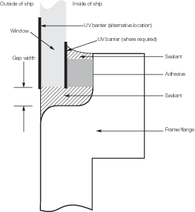
Figure 2.10.1 Gap width between flange and window, bonded from outside of the ship
10.6.9 The
minimum adhesive width and thickness are to be in accordance with
the adhesive manufacturer’s published guidelines.
|