
Section
6 Miscellaneous openings
6.1 Small hatchways on exposed decks
6.1.1 Hatches
which:
- are designed for access to spaces below the deck;
- are capable of being closed weathertight or watertight, as applicable;
- have an opening 2,5 m2 or less;
- are located on the exposed deck over the forward 0,25L of
the ship’s rule length;
- are on a ship of sea-going service of length 80 m or more, where
the height of the exposed deck in way of the hatch is less than 0,1L or 22 m above the summer load waterline, whichever is the
lesser;
are to comply with the requirements of Pt 3, Ch 11, 6.6 Small hatchways on exposed fore decks. All other small hatchways or
access openings in the positions defined in Pt 3, Ch 11, 1.1 Application 1.1.6 are to comply with the following
requirements.
6.1.2 The
number and size of hatchways and other access openings are to be kept
to the minimum consistent with the satisfactory operation of the ship.
6.1.3 The
height of coamings is to be in accordance with Pt 3, Ch 11, 5.1 General 5.1.1. Lower heights may be considered
in relation to operational requirements and the nature of the spaces
to which access is given.
6.1.4 Rope
hatches may be accepted with reduced coamings, but generally not less
than 380 mm, provided they are well secured and closed before the
ship leaves port. A suitable notice is to be displayed at the hatch
stating that it is to be closed whilst the ship is at sea.
6.1.5 The
thickness of the coamings is to be not less than the Rule minimum
thickness for the deck inside line of openings for that position,
or 11 mm, whichever is the lesser. Stiffening of the coaming is to
be appropriate to its length and height.
6.1.6 Hatch
covers are to be of steel, weathertight and generally hinged. The
means of securing are to be such that weathertightness can be maintained
in any sea condition. Where toggles are fitted, their diameter and
spacing are to be in accordance with ISO Standard or equivalent.
6.1.7 Hinges
are not to be used as securing devices unless specially considered.
6.1.8 The
thickness of covers is to be not less than the Rule minimum thickness
inside the line of openings for the deck at that point, or 8 mm, whichever
is the lesser.
6.1.9 The
covers are to be adequately stiffened.
6.1.10 To
facilitate a swift and safe means of escape to the lifeboat and life
raft embarkation deck, the following provisions apply to overhead
hatches fitted along the escape routes addressed by SOLAS Regulation 13 - Means of escape:
-
escape hatches
and their securing devices shall be of a type which can be opened
from both sides;
-
the maximum
force needed to open the hatch cover should not exceed 150 N; and
-
the use of a
spring equalising, counterbalance or other suitable device on the
hinge side to reduce the force needed for opening is acceptable.
6.1.11 Small
hatches, including escape hatches, are to be situated clear of cargo
containment areas, particularly in the case of offshore supply ships.
6.1.12 Where
portable plates are required in decks for unshipping machinery, or
for other similar reasons, they may be accepted provided they are
of equivalent strength to the unpierced deck and are secured by gaskets
and closely spaced bolts at a pitch not exceeding five diameters.
6.1.14 Where
permitted by the National Authority, access hatch coaming heights
may be reduced on ships engaged on protected or extended protected
water service. Coaming heights are to be as high as practicable with
a minimum height of 230 mm.
6.2 Manholes and flush scuttles
6.2.1 Manholes
and flush scuttles fitted in Positions 1 and 2, or within superstructures
other than enclosed superstructures, are to be closed by substantial
covers capable of being made watertight. Unless secured by closely
spaced bolts, the covers are to be permanently attached.
6.3 Hatchways within enclosed superstructures or 'tween decks
6.3.2 Access
hatches within a superstructure or deckhouse in Position 1 or 2 need
not be provided with means for closing if all openings in the surrounding
bulkheads have weathertight closing appliances.
6.4 Companionways, doors and accesses on weather decks
6.4.1 Companionways on exposed decks are to be of equivalent construction,
weathertightness and strength to a deckhouse in the same position and effectively
secured to the deck.
6.4.2 Access openings in:
-
bulkheads at ends of enclosed superstructures;
-
deckhouses or companionways protecting openings leading into enclosed
superstructures or to spaces below the freeboard deck; and
-
deckhouse on a deckhouse protecting an opening leading to a space
below the freeboard deck
are to be fitted with doors of steel or other equivalent material,
permanently and strongly attached to the bulkhead and framed, stiffened and fitted so
that the whole structure is of equivalent strength to the unpierced bulkhead, and
weathertight when closed. The doors are to be gasketed and secured weathertight by means
of clamping devices or equivalent arrangements, permanently attached to the bulkhead or
to the door. Doors are generally to open outwards and are to be capable of being
operated and secured from both sides. The sill heights are to be as required by Pt 3, Ch 11, 6.4 Companionways, doors and accesses on weather decks 6.4.6. See also
Pt 3, Ch 11, 7 Tanker access arrangements and closing appliances and Pt 4, Ch 9, 13 Access arrangements and closing appliances and Pt 4, Ch 11, 1 General and the Rules for Ships for Liquid Chemicals, Ship ArrangementsChapter 3 concerning access
openings in tankers, chemical tankers and ore or oil ships. Double doors are to be
equivalent in strength to the unpierced bulkhead, and in Position 1, a centre pillar is
to be provided which may be portable.
6.4.3 Elsewhere doors may be of hardwood not less than 50 mm in thickness or of
equivalent material and strength.
6.4.5 The height of doorway sills above deck sheathing of access openings in bulkheads at ends
of enclosed superstructures is to be not less than 600mm in Position 1 and not less than
380mm otherwise.
6.4.6 The height of doorway sills above deck sheathing, if fitted, is to be not
less than 600 mm in Position 1, and not less than 380 mm in Position 2.
6.4.7 Where access is provided from the deck above as an alternative to access
from the freeboard deck, the height of sill into a bridge or a poop is to be not less
than 380 mm. The same requirement applies to deckhouses on the freeboard deck. The sill
height for doorways in a forecastle, if protecting a companionway, is to be 600 mm
regardless of whether or not access is provided from above. If not protecting a
companionway, the sill height may be 380 mm.
6.4.9 Where an access opening, in the top of a deckhouse situated on a raised
quarterdeck, gives access below the freeboard deck or to an enclosed superstructure, the
closing appliances in the surrounding bulkheads are not required to be gasketed,
provided the raised quarterdeck is at least standard height, and the deckhouse is at
least standard superstructure height.
6.4.10 The height of door sills may be required to be increased on ships of Type
`A', Type `B-100' or Type `B-60' where this is shown to be necessary by the floatability
calculations required by the International Convention on Load Lines, 1966.
6.4.11 Where doors in locations above Position 2 are included in the consideration
of intact and damage stability or are in critical locations above Position 2, then the
height of door sills is to be specially considered.
6.4.12 Direct access from the freeboard deck to the machinery space through
exposed casings is not permitted on ships of Type `A', Type `B-100' or Type `B-60'. A
door complying with Pt 3, Ch 11, 6.4 Companionways, doors and accesses on weather decks 6.4.2 may, however, be fitted in an exposed machinery
casing on these ships, provided that it leads to a space or passageway which is of
equivalent strength to the casing and is separated from the machinery space by a second
weathertight door complying with Pt 3, Ch 11, 6.4 Companionways, doors and accesses on weather decks 6.4.2. The outer and inner weathertight doors are to have
sill heights of not less than 600 mm and 230 mm, respectively and the space between is
to be adequately drained by means of a screw plug or equivalent.
6.4.13 For a Type `A' ship with freeboards assigned greater than, or equal to,
Type `B', inner doors are not required for direct access to the engine-room.
6.4.14 If internal access is provided from a wheelhouse in Position 2, or below,
to spaces below the weather deck either directly or through other spaces, the opening
should be protected by a hinged weathertight cover adequately secured, fitted on a
coaming appropriate to its position, or by an equivalent arrangement, and the space
adequately drained.
6.4.15 In way of a moonpool, where a working or platform deck is provided below
the weather deck, openings in the surrounding bulkheads are to be kept to a minimum.
Access or companionway openings are to be provided with weathertight closing appliances
as for an exposed superstructure bulkhead, with 600 mm high coamings.
6.4.16 Where portable plates are required in casings for unshipping machinery, or
for other similar reasons, they may be accepted provided they are of equivalent strength
to the unpierced bulkhead and are secured by gaskets and close spaced bolts at a pitch
not exceeding five diameters.
6.4.17 The sill heights of accesses closed by covers which are secured by closely
spaced bolts or otherwise kept permanently closed at sea will be specially
considered.
6.4.18 Where permitted by the National Authority, companionway coaming heights may
be reduced on ships engaged on protected or extended protected water service. Coaming
heights are to be as high as practicable with a minimum height of 230 mm. Where the
wheelhouse is on the freeboard deck, or located in the forward quarter of the ship's
length, with internal access below, a weathertight cover, fitted to a coaming not less
than 230 mm high, is to be provided for the access. Alternatively, storm covers are to
be provided for windows in exposed positions. The wheelhouse is to be adequately
drained.
6.5 Side scuttles, windows and skylights
6.5.1 Side scuttles are defined as being round or oval openings with an area not exceeding
0,16 m2.
6.5.2 Windows are defined as being rectangular openings generally, having a radius at each
corner relative to the window size in accordance with a recognised National or
International Standard, and round or oval openings with an area exceeding 0,16
m2.
6.5.3 Deadlights are fitted to the inside of windows and side scuttles while storm covers,
of comparable specifications to deadlights, are fitted to the outside of windows,
where accessible. Deadlights can be hinged and storm covers can be hinged or
portable.
6.5.4 A plan showing the location of side scuttles and windows is to be submitted.
Attention is to be given to any relevant Statutory Requirements of the National
Authority of the country in which the ship is to be registered.
6.5.5 Side scuttles and windows together with their glasses, deadlights and
storm covers if fitted, are to be of an approved design or in accordance with a
recognised National or International Standard. The minimum design pressures to which
windows and side scuttles are to be designed are to be in accordance with Pt 3, Ch 8 Superstructures, Deckhouses and Bulwarks unless otherwise
specified by the relevant requirements of Pt 4 Ship Structures (Ship Types)
6.5.7 Side scuttles to spaces below the freeboard deck, or to spaces within the first tier
of enclosed superstructures, or to first tier deckhouses on the freeboard deck
protecting openings leading below or considered buoyant in stability calculations,
are to be fitted with efficient, hinged, inside deadlights.
6.5.8 Deadlights are to be capable of being closed and secured watertight if fitted below
the freeboard deck or weathertight if fitted above.
6.5.9 No side scuttle is to be fitted in such a position that its sill is
below a line drawn parallel to the freeboard deck at side and having its lowest
point 2,5 per cent of the breadth B above the load waterline corresponding to
the summer freeboard (or timber summer freeboard if assigned), or 500 mm, whichever
is the greater distance, see
Figure 11.6.1 Side Scuttle Positioning
6.5.10 If the required damage stability or floatability calculations indicate that the side
scuttles would become immersed at any intermediate stages of flooding or the final
equilibrium waterline, these are to be of the non-opening type.
6.5.11 Windows are not to be fitted below the freeboard deck, in first tier end bulkheads or
sides of enclosed superstructures, or in first tier deckhouses that are considered
buoyant in stability calculations or protecting openings leading below.
6.5.12 Where windows are fitted in a deckhouse in the first tier, they are to
be provided with strong, hinged, steel, weathertight storm covers. However, if there
is an opening leading below deck in this deckhouse, this opening is to be treated as
being on an exposed deck and is to be protected as required by Pt 3, Ch 11, 6.4 Companionways, doors and accesses on weather decks 6.4.2.
6.5.13 Where windows are permitted in an exposed bulkhead on the weather deck in the forward
0,25 of the load line length, strong external storm covers which can be portable and
stored adjacent are to be provided.
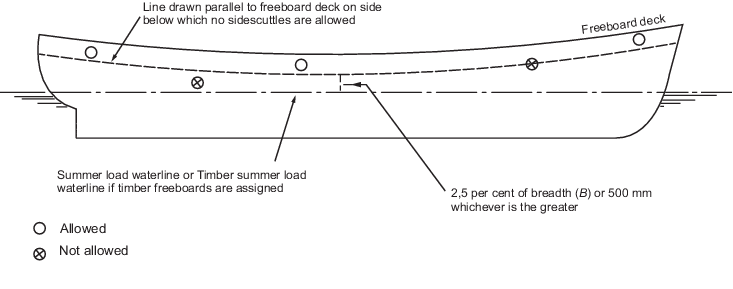
Figure 11.6.1 Side Scuttle Positioning
6.5.14 Side scuttles and windows at the side shell in the second tier protecting direct
access below or spaces considered buoyant in stability calculations are to be
provided with efficient inside deadlights capable of being effectively closed and
secured weathertight.
6.5.15 Side scuttles and windows set inboard from the side shell in the second
tier protecting direct access below to spaces listed in Pt 3, Ch 11, 6.5 Side scuttles, windows and skylights 6.5.7, are to be provided with either efficient hinged inside deadlights
or, where they are accessible, permanently attached external storm covers of
approved design and of substantial construction and capable of being effectively
closed and secured weathertight.
6.5.16 Cabin bulkheads and doors in the second tier separating side scuttles and windows
from a direct access leading below may be accepted in place of deadlights or storm
covers fitted to the side scuttles or windows.
6.5.17 Side scuttles and windows set inboard from the side shell in the second tier, not
protecting direct access below or spaces considered buoyant in the stability
calculations, do not require deadlights or storm covers.
6.5.18 If fitted in a deckhouse in the second tier located within the forward
0,25 of the load line length windows are to be provided with strong, hinged, steel,
weathertight storm covers. However, if there is an opening leading below deck in
this deckhouse, this opening is to be treated as being on an exposed deck and is to
be protected as required by Pt 3, Ch 11, 6.4 Companionways, doors and accesses on weather decks 6.4.2.
6.5.19 Where the wheelhouse is in the second tier located abaft the forward 0,25 of the load
line length, in lieu of storm covers being provided for the wheelhouse windows, a
weathertight cover, fitted to a coaming of not less than 230 mm in height around the
internal stairway opening within the wheelhouse, can be accepted. If this
arrangement is accepted, adequate means of draining the wheelhouse are to be
provided.
6.5.20 Deckhouses or superstructure situated on a raised quarter deck or on the deck of a
superstructure of less than standard height or on the deck of a deckhouse of less
than standard height can be regarded as being in the second tier as far as the
provision of deadlights is concerned, provided that the height of the raised quarter
deck, superstructure or deckhouse is equal to, or greater than, the standard quarter
deck height.
6.5.21 Where the wheelhouse is in the third tier located in the forward 0,25 of the load
line length, in lieu of storm covers being provided for the wheelhouse windows, a
weathertight cover, fitted to a coaming of not less than 230 mm in height around the
internal stairway opening within the wheelhouse, can be accepted. If this
arrangement is accepted, adequate means of draining the wheelhouse are to be
provided.
6.5.22 Windows at the side shell in the third tier are to be provided with strong portable
internal storm covers for 25 per cent of each size of window, with means of securing
being provided at each window.
6.5.23 Windows at the side shell in the fourth tier located in the forward 0,25 of the load
line length are to be provided with strong portable internal storm covers for 25 per
cent of each size of window, with means of securing being provided at each
window.
6.5.24 If necessary, for practical considerations, storm covers can be in two parts.
6.5.25 For windows in the second tier and higher above the freeboard deck, a
glazing equivalent can be fitted in lieu of deadlights/storm covers. The thicknesses
and arrangements are to be acceptable to the National Authority with whom the ship
is registered. For arrangements of glazing acceptable to LR, see
Table 11.6.1 Acceptable arrangements of glazing in lieu of portable storm
covers/deadlights. Other glazing
equivalents will be considered on a case-by-case basis.
6.5.26 Windows are not to be fitted in machinery space boundaries. However, this does not
preclude the use of glass in control rooms within the machinery space.
6.5.27 Skylights, where fitted, are to be of substantial construction and
securely attached to their coamings. The height of the lower edge of the opening is
to be as required by Pt 3, Ch 11, 5.1 General 5.1.1. The scantlings of the
coaming are to be as required by this Section or Pt 3, Ch 11, 5 Hatch coamings, as appropriate. The thickness of glasses
in fixed or opening skylights is to be appropriate to their size and position as
required for side scuttles or windows. Glasses in any position are to be protected
from mechanical damage and, where fitted in Positions 1 or 2, are to be provided
with robust deadlights or storm covers permanently attached. Cargo pump room and
machinery space skylights are not to contain glass.
6.5.28 Skylights to cargo pump rooms are to be capable of being closed from outside the pump
room.
Table 11.6.1 Acceptable arrangements of glazing in lieu of portable storm
covers/deadlights
6.5.29 Laminated toughened safety glass may also be used for windows but the total thickness
will need to be greater than that required for the equivalent sized window using
toughened safety glass. The equivalent thickness of laminated toughened safety glass
is to be determined from the following formula:
|
n |
= |
number of laminates |
|
TLi |
= |
thickness of glass laminate |
|
Ts |
= |
thickness of toughened safety glass |
Alternative arrangements that do not meet the above thickness requirement will be
specially considered, provided that equivalent strength and bending stiffness to
that of a single, thermally toughened pane of thickness, Ts, can
be demonstrated in a four-point bending test as described in EN-ISO 1288-3 or an
equivalent recognised National or International Standard, using not less than ten
samples. The lower limit of the 90 per cent confidence level interval for the
laminated pane shall not be less than the same for monolithic toughened safety
glass. Small scale punch test or ring-in-ring test methods shall not be used.
6.5.30 Non-metallic frames are not acceptable for windows in the first and second tiers, and
are not generally acceptable in any other position in external casings. Any
proposals to fit non-metallic frames are to be submitted for consideration, and are
to be acceptable to the Administration. The proposed locations, frame dimensions,
glass thicknesses and the results of any tests carried out, are to be forwarded.
6.6 Small hatchways on exposed fore decks
6.6.2 The
number and size of hatchways and other access openings are to be kept
to the minimum consistent with the satisfactory operation of the ship.
6.6.3 The
height of coamings is to be in accordance with Pt 3, Ch 11, 5.1 General 5.1.1. Lower heights may be considered
in relation to operational requirements and the nature of the spaces
to which access is given.
6.6.4 Rope
hatches may be accepted with reduced coamings, but generally not less
than 380 mm, provided they are well secured and closed before the
ship leaves port. A suitable notice is to be displayed at the hatch
stating that it is to be closed whilst the ship is at sea.
6.6.5 Where
permitted by the National Authority, access hatch coaming heights
may be reduced on ships engaged on protected or extended protected
water service. Coaming heights are to be as high as practicable with
a minimum height of 230 mm.
6.6.6 The
thickness of the coamings is to be not less than the Rule minimum
thickness for the deck inside line of openings for that position,
or 11 mm, whichever is the lesser.
6.6.7 The
upper edge of the hatchway coamings is to be suitably reinforced by
a horizontal section, normally not more than 170 to 190 mm from the
upper edge of the coamings.
6.6.8 Hatches
are to be fitted with primary securing devices such that their hatch
covers can be secured in place and weather-tight by means of a mechanism
employing any one of the following methods:
-
Butterfly nuts
tightening onto forks (clamps),
-
Quick acting
cleats, or
-
Central locking
device.
Emergency escape hatches are excluded from options (a) and (b).
6.6.9 Dogs
(twist tightening handles) with wedges are not acceptable as primary
securing devices.
6.6.10 Escape
hatches are to be capable of being opened from either side and are
to have a quick-acting type securing device, e.g. one action wheel
handle central locking device for latching/unlatching the hatch cover.
6.6.11 For
a primary securing method using butterfly nuts, the forks (clamps)
are to be of robust design. They are to be designed to minimise the
risk of butterfly nuts being dislodged while in use; by means of curving
the forks upward, a raised surface on the free end, or a similar method.
The plate thickness of unstiffened steel forks is not to be less than
16 mm. An example arrangement is shown in Figure 11.6.3 Example of a primary securing method.
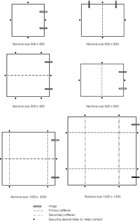
Figure 11.6.2 Arrangement of stiffeners
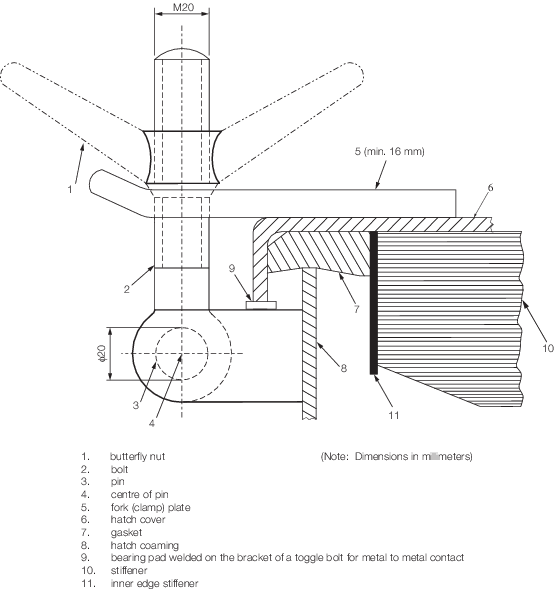
Figure 11.6.3 Example of a primary securing method
6.6.12 The
hatch cover is to be fitted with a gasket of elastic material. This
is to be designed to allow a metal to metal contact at a designed
compression and to prevent over compression of the gasket by green
sea forces that may cause the securing devices to be loosened or dislodged.
The metal-to-metal contacts are to be arranged close to each securing
device in accordance with Figure 11.6.2 Arrangement of stiffeners,
and of sufficient capacity to withstand the bearing force.
6.6.13 The
primary securing method is to be designed and manufactured such that
the designed compression pressure can be achieved by one person without
the need of any tools.
6.6.14 For
small rectangular steel hatch covers, the plate thickness, stiffener
arrangement and scantlings are to be in accordance with Table 11.6.2 Scantlings for small steel hatch
covers on exposed deck and Figure 11.6.2 Arrangement of stiffeners. Stiffeners, where
fitted, are to be aligned with the metal-to-metal contact points required
in Pt 3, Ch 11, 6.6 Small hatchways on exposed fore decks 6.6.11, see
Figure 11.6.2 Arrangement of stiffeners. Primary stiffeners
are to be continuous. All stiffeners are to be welded to the inner
edge stiffener, see
Figure 11.6.3 Example of a primary securing method.
Table 11.6.2 Scantlings for small steel hatch
covers on exposed deck
| nominal
|
cover
|
primary
|
secondary
|
| size
|
plate
|
stiffeners
|
stiffeners
|
| (mm x mm)
|
thickness
|
Flat bar (mm x mm);
|
|
|
(mm)
|
number
|
| 630 x 630
|
8
|
–
|
–
|
| 630 x 830
|
8
|
100 x 8,1
|
–
|
| 830 x 630
|
8
|
100 x 8,1
|
–
|
| 830 x 830
|
8
|
100 x 10,1
|
–
|
| 1030 x 1030
|
8
|
120 x 12,1
|
80 x 8,2
|
| 1330 x 1330
|
8
|
150 x 12,2
|
100 x 10,2
|
6.6.15 For
hatch covers constructed of materials other than steel, the required
scantlings are to provide equivalent strength.
6.6.16 For
small hatch covers of circular or similar shape, the cover plate thickness
and reinforcement are to be of equivalent strength to that of the
small rectangular steel hatch covers described in Pt 3, Ch 11, 2.2 Stiffener arrangement 2.2.1.
6.6.17 For
hatch covers located on the deck forward of the fore-most cargo hatch,
the hinges are to be fitted such that the predominant direction of
green sea will cause the cover to close. The hinges are normally to
be located on the fore edge.
6.6.18 On
small hatches located between the main hatches, for example between
Numbers 1 and 2, the hinges are to be placed on the fore edge or outboard
edge, whichever is practicable for protection from green water in
beam sea and bow quartering conditions.
6.6.19 Hatches,
excluding emergency escape hatches, are to be fitted with an independent
secondary securing device, e.g. by means of a sliding bolt, a hasp
or a backing bar of slack fit, which is capable of keeping the hatch
cover in place, even in the event that the primary securing device
became loosened or dislodged. It is to be fitted on the side opposite
to the hatch cover hinges.
6.6.20 Small
hatches, including escape hatches, are to be situated clear of cargo
containment areas, particularly in the case of offshore supply ships.
6.6.21 Where
portable plates are required in decks for unshipping machinery, or
for other similar reasons, they may be accepted provided they are
of equivalent strength to the unpierced deck and are secured by gaskets
and closely spaced bolts at a pitch not exceeding five diameters.
|