
Section
1 General
1.1 Application
1.1.1 This
Chapter applies to the arrangements and scantlings within the cargo
region of sea-going ore carriers, intended for the carriage of ore
in centre holds.
1.1.3 The
scantlings of structural items may be determined by direct calculation.
Where the length of the ship exceeds 150 m, the scantlings of the
primary supporting structure and the fatigue performance of structural
details are to be assessed in accordance with the relevant ShipRight
procedures, see
Pt 4, Ch 11, 1.3 Class notation 1.3.5.
In such cases, the calculations are to be submitted for approval.
1.2 Structural configuration and ship arrangement
1.2.1 The requirements contained in the Chapter apply to single deck ships with
machinery aft, having two longitudinal bulkheads and a double bottom throughout the
centre hold. A typical cross-section is indicated in Figure 11.1.1 Typical cross-section.
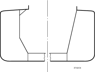
Figure 11.1.1 Typical cross-section
1.2.2 The bottom, and the deck outside the line of ore hatchways, are to be
framed longitudinally within the cargo region. The side shell and longitudinal bulkheads
are generally to be framed longitudinally where the length of the ship exceeds 150 m,
but alternative proposals will be specially considered. Inside the line of openings, the
deck is to be transversely framed.
1.2.3 The notation Strengthened to carry cargoes which may liquefy (IMSBC Group A) is
only applicable to ore carriers having a conventional structural configuration with
cargo holds bounded by two longitudinal bulkheads widely separated from the side shell,
see
Figure 11.1.1 Typical cross-section.
1.3 Class notation
1.3.1 Sea-going ships complying with the requirements of this Chapter and other
relevant Rule requirements for the draught required will be eligible to be classed
100A1 ore carrier, ESP.
1.3.3 Where a vessel is built in accordance with the requirements detailed in this Section,
the vessel will be eligible for the notation Strengthened to carry cargoes which may
liquefy (IMSBC Group A). The requirements in this Section do not allow the
loading of cargo with moisture content in excess of the transportable moisture limit
(TML), as defined in the IMSBC Code, but instead make allowance for the rise in moisture
content of the cargo above the TML after loading. Attention is drawn to Section 7.3.2.1
of the IMSBC Code.
1.3.4 The notation Strengthened to carry cargoes which may liquefy (IMSBC
Group A) serves to identify the ship as being specially constructed for loads
from Group A cargoes, as defined in the IMSBC Code.
The loading condition cargo density, ρc, applicable to this
notation is not to be less than the virtual homogeneous load density as calculated based
on MFull at maximum draught, see
Pt 4, Ch 7, 1.8 Symbols and definitions. The
virtual cargo density is calculated based on homogeneous cargo at maximum draught.
The density is to be agreed between the Owner and the Builder and is to be noted in the
Loading Manual in this form: ‘Carriage of cargo with moisture content above TML shall
only be undertaken if the cargo density is above <density> t/m3’.
To be eligible for this notation additional calculations are required to assess stresses
from liquefied cargo. The following structures are to be assessed:
- Longitudinal bulkheads using one of the following cargo
density cases:
- Assessment using virtual cargo density, i.e. fully
filled:
- Assessment using cargo density higher than the virtual
cargo density, i.e. partially filled:
- According to Table 9.6.1 Inner hull and longitudinal
oiltight bulkhead scantlings with the following
considerations:
- load height, h, measured up to the height
of the cargo in the hold;
- horizontal distance, b1,
measured from the calculation point to the centreline as the filling
level allows. When the level of the liquefied cargo is above the hold
corner after the ship is heeled over, b1 is to be
specially considered to ensure a correct increased load height,
h + R b1, in the heeled state with roll
angle θ; and
- the results are to be corrected for density by
applying a factor of ρc/1,025 to the load height.
- Transverse bulkheads using one of the following cargo density
cases:
- Assessment using virtual cargo density, i.e. fully
filled:
- According to Table 9.7.1 Transverse oiltight bulkhead
scantlings with the following considerations:
- load height, h, measured to the highest
point of the hold; and
- the results are to be corrected for density by
applying a factor of ρc/1,025 to the load
height.
- Assessment using cargo density higher than the virtual
cargo density, i.e. partially filled:
- According to Table 9.7.1 Transverse oiltight bulkhead
scantlings with the following considerations:
- load height, h, measured up to the height
of the cargo in the hold;
- horizontal distance, b1,
measured from the calculation point to the centreline as the filling
level allows. When the level of the liquefied cargo is above the hold
corner after the ship is heeled over, b1 is to be
specially considered to ensure a correct increased load height,
h + R b1, in the heeled state with roll
angle θ; and
- the results are to be corrected for density by
applying a factor of ρc/1,025 to the load height.
- Intersection of continuous secondary and primary members
according to Pt 3, Ch 10, 5.2 Arrangements at intersections of continuous secondary and primary members using loads in the same Section
from Table 10.5.1 Total load transmitted to
connection of secondary members
(3)(b)(iii) in Pt 3 Ship Structures (General) with Kc = 1.
- Cross ties in wing tanks as per requirements for primary
structure in this Chapter.
- Lower stool as per requirements for Pt 4, Ch 11, 1.3 Class notation 1.3.4.(c) transverse bulkheads.
Additionally, the vessel is to be designed in accordance with LR’s
ShipRight SDA Procedure for Primary Structures of Ore Carriers..
1.3.5 Where the length of the ship is greater than 150 m, or where the structural
arrangements are considered such as to necessitate it, the scantlings of the primary
supporting structure are to be assessed by direct calculation and the ShipRight
notations SDA, FDA and CM are mandatory, see
Pt 4, Ch 11, 1.3 Class notation 1.3.7 and Pt 4, Ch 11, 11 Direct calculations.
1.3.6 For ore carriers where an assessment of multiple port loading and unloadinghas been
carried out in accordance with the relevant ShipRight procedures and the ShipRight
notation SDA has been assigned, an optional ShipRight notation MP can be
assigned.
1.4 Symbols and definitions
1.4.1 The
following symbols and definitions are applicable to this Chapter unless
otherwise stated:
L, B, D, T as
defined in Pt 3, Ch 1, 6 Definitions.
|
b
|
= |
the
width of plating supported by the primary member, in metres or mm |
|
h
|
= |
the
load head, in metres, applied to the item under consideration |
|
s
|
= |
spacing,
in mm, of secondary members |
|
Z
|
= |
the
section modulus, in cm3, of the primary or secondary member,
in association with an effective width of attached plating determined
in accordance with Pt 3, Ch 3, 3 Structural idealisation.
|
1.4.2 The
expression `primary member' as used in this Chapter is defined as
a girder, transverse, vertical web, stringer, cross-tie, buttress
or double bottom floor. `Secondary members' are supporting members
other than primary members.
|