
Section
5 Hatch coamings
5.1 General
5.1.1 The height of coamings above the upper surface of the deck, measured above
sheathing if fitted, for hatchways closed by portable covers secured weathertight by
tarpaulins and battening devices, is to be not less than:
- 600 mm at Position 1,
- 450 mm at Position 2.
5.1.2 Where hatches in locations above Position 2 are included in the consideration of intact
and damage stability or are in critical locations above Position 2, then the height of
hatch coamings is to be specially considered.
5.1.3 The height of coamings of hatchways situated in Positions 1 and 2 closed by
steel covers fitted with gaskets and clamping devices are to be as specified in Pt 3, Ch 11, 5.1 General 5.1.1, but may be reduced, or the coamings may be omitted
entirely, if the safety of the ship is not thereby impaired in any sea condition.
Special attention will be given in such cases to the scantlings of the covers, to their
gasketing and securing arrangements and to the drainage of recesses in the deck. The
agreement of the National Authority concerned will also be required.
5.1.4 The height of coamings may be required to be increased on ships of Type
`B-100' or Type `B-60' where this is shown to be necessary by the floatability
calculations required by the International Convention on Load Lines, 1966.
5.2 Construction
5.2.1 Vertical
cargo hatch coamings 600 mm or more in height are to be stiffened
on their upper edges by a horizontal bulb flat or equivalent which
is to be not less than 180 mm in width for ships where L is
greater than 75 m. Additional support is to be afforded by fitting
brackets or stays from the bulb flat to the deck at intervals of not
more than 3 m. Each bracket or stay is to be aligned with suitable
underdeck stiffeners and is to have a softened nose.
5.2.2 Vertical coamings less than 600 mm in height are to be stiffened at their
upper edge by a substantial rolled or fabricated section. Additional support is to be
arranged as required by Pt 3, Ch 11, 5.2 Construction 5.2.1.
5.2.4 The
scantlings and arrangements of hatch coamings acting as girders will
be specially considered. The coamings are to be arranged with intermediate
continuous horizontal stiffeners supported by the bracket stays.
5.2.5 Sloped
cargo hatch coamings will be specially considered. In general, the
sloped coaming arrangement is to be restricted to the hatch side coamings
with vertical coamings at the ends. The sloped coaming is not to have
a knuckle and the angle to the vertical is not to exceed 30°.
The scantlings are to be in accordance with Pt 3, Ch 11, 5.2 Construction 5.2.1, Pt 3, Ch 11, 5.2 Construction 5.2.2 and Pt 3, Ch 11, 5.3 Strength criteria, except that the end coamings
are to be increased by 20 per cent for a distance of 0,15b from
the side coamings where b is the width of the hatchway
at the deck. Particular care is to be taken where the proposed loadings
exceed those given in Pt 3, Ch 11, 2.3 Load model and Pt 3, Ch 3, 5 Design loading, and where the coamings are not
in alignment with the topside tank vertical strake in bulk carriers.
5.2.6 A radiused
coaming plate at the corner junction of the longitudinal and transverse
cargo hatch coamings is acceptable for ships where L ≤
90 m and the heights of coamings are not in excess of that specified
in Pt 3, Ch 11, 5.1 General 5.1.1. Where L >
90 m the corner junctions are to be rectangular and arranged with
continuation brackets as required by Pt 3, Ch 11, 5.2 Construction 5.2.8.
5.2.7 The
deck plating is to extend inside the coamings and the side coamings
are to be extended in the form of tapered brackets. A recommended
arrangement is shown in Figure 11.5.1 Coaming continuation bracket - Recommended arrangement.
Continuation brackets are also to be arranged athwartships in line
with the hatch end coamings and the under deck transverse. In bulk
carriers the athwartship brackets, in conjunction with the hatch end
beams should be arranged to achieve a satisfactory overlap with the
top side tank transverses. In cases where the hatch end beam is formed
by the transverse bulkhead top stool the horizontal knuckle of the
stool should be arranged well clear of the topside tank knuckle line.
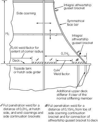
Figure 11.5.1 Coaming continuation bracket - Recommended arrangement
5.2.8 In
bulk carriers where the hatch side coaming does not align with the
topside tank vertical strake the arrangement and scantlings will be
specially considered. In general, suitable underdeck girders and cantilever
brackets are to be arranged taking into consideration the hatch cover
loading. The underdeck girders are to continue beyond the hatch end
for a distance of 2H
c mm. Alternative arrangements
incorporating bulkhead top stool structure or cross-deck structure
will be considered.
5.2.9 Extension
brackets or rails arranged approximately in line with the cargo hatch
side coamings and intended for the stowage of steel covers are not
to be welded to a deckhouse, masthouse or to each other unless they
form part of the longitudinal strength members.
5.2.11 Where
containers are carried on multi-panel hatch covers, the hatch coaming
in way of the loaded panel will be required to be reinforced to resist
the lateral loads imposed on the coaming due to rolling of the ship.
Thrust blocks are to be fitted on the coaming rest bar to prevent
the covers from moving. Where one-piece hatch covers are fitted with
locating devices, the coamings are to be reinforced in way of the
locators.
5.2.12 Cut
outs in the top of hatch coamings are to be avoided. Where these are
necessary for the securing devices they are to be circular or elliptical
in shape. Also any local reinforcements should be given a tapered
transition in the longitudinal direction with a taper the rate of
which should not exceed 1 in 3. Cut-outs and drain holes are to be
avoided in the hatch side coaming continuation brackets. Where these
are necessary the size, shape and position will be specially considered.
5.2.13 Material
for hatch coamings is to be steel, according to the requirements for
ship’s hull. Alternative materials will be subject to special
consideration.
5.2.14 Secondary
stiffeners of hatch coamings are to be continuous over the breadth
and length of hatch coamings.
5.2.15 Longitudinal
hatch coamings with a length exceeding 0,1L m are to
be provided with tapered brackets or equivalent transitions and a
corresponding substructure at both ends. At the end of the brackets
they are to be connected to the deck by full penetration welds of
minimum 300 mm in length.
5.2.16 Hatch
coamings and supporting structures are to be adequately stiffened
to accommodate the loading from hatch covers, in longitudinal, transverse
and vertical directions. Structures under deck are to be checked against
the load transmitted by coaming stays.
5.2.17 On
ships carrying cargo on deck, such as timber, coal or coke, coaming
stays are to be spaced not more than 1,5 m apart.
5.2.18 Coaming plates are to extend to the lower edge of the deck beams; they or
hatch side girders are to be fitted that extend to the lower edge of the deck beams.
Extended coaming plates and hatch side girders are to be flanged or fitted with face
bars or half-round bars. Figure 11.5.2 Example of hatch side
girder and Figure 11.5.3 Example of coaming stays give examples.

Figure 11.5.2 Example of hatch side
girder
5.3 Strength criteria
5.3.1 The
strength requirements in this Section are applicable to hatch coamings
of stiffened plate construction.
5.3.2 The
local net plate thickness of weather deck hatch coamings is not to
be less than the larger of the following values:
|
|
= |
where |
|
s
|
= |
stiffener
spacing, in mm |
|
L
1
|
= |
L need not be taken greater than 300 metres
|
|
pA
|
= |
pressure, in kN/m2, as defined in Pt 3, Ch 11, 2.3 Load model 2.3.3
|
|
|
= |
Longitudinal strength aspects are to be observed. |
5.3.3 Secondary
stiffeners of coamings must be continuous at the coaming stays. For
stiffeners with both ends constrained, the elastic net section modulus Z in cm3 and net shear area A
S in
cm2, calculated on the basis of net thickness, are not
to be less than:
|
|
= |
where |
|
l |
= |
secondary
stiffener span, in metres, to be taken as the spacing of coaming stays |
|
s
|
= |
stiffener
spacing in mm |
|
pA
|
= |
pressure, in kN/m2, as defined in Pt 3, Ch 11, 2.3 Load model 2.3.3.
|
5.3.4 For
sniped stiffeners at coaming corners, section modulus and shear area
at the fixed support are to be increased by 35 per cent. The gross
thickness of the coaming plate at the sniped stiffener end is not
to be less than:
5.3.6 At the connection with deck, the net
section modulus Z, in cm3, and the gross thickness
tw, in mm, of the coaming stays designed as beams with flange
(examples 1 and 2 are shown in Figure 11.5.3 Example of coaming stays) are to be taken not less
than:
and
where
|
e
|
= |
spacing of coaming stays, in metres |
|
hs |
= |
height of coaming stays, in metres |
|
hw |
= |
web height of coaming stay at its lower end, in metres |
|
tc |
= |
corrosion addition, in mm, according to Table 11.1.2 Corrosion addition t
c
|
|
p
A
|
= |
pressure, in kN/m2, as defined in Pt 3, Ch 11, 2.3 Load model 2.3.3. |
|
σo |
= |
minimum yield stress, in N/mm2. |
5.3.8 Coaming
stays are to be supported by appropriate substructures. Face-plates
may be included in the calculation only if an appropriate substructure
is provided and welding ensures an adequate joint.
5.3.9 Webs
of coaming stays are to be connected to the deck by fillet welds on
both sides with a throat thickness of a = 0,44t
w.
5.3.11 Hatch
coamings which are part of the longitudinal hull structure are to
be designed according to the requirements for longitudinal strength
in Pt 3, Ch 4 Longitudinal Strength.
5.3.12 For
structural members welded to coamings and for cut-outs in the top
of coamings, sufficient fatigue strength is to be verified.
5.4 Rest bars in hatchways
5.4.1 Rest
bars are to provide at least 65 mm bearing surface and are to be aligned
if required to suit the slope of the hatches.
5.5 Loading in excess of Rule requirements
|