
Section
2 Longitudinal strength
2.1 General
2.1.1 Longitudinal strength calculations are to be made in accordance with the
requirements given in Pt 3, Ch 4 Longitudinal Strength and the additional notes contained in this Section.
2.1.4 For ships where the side shell or side casings contain large openings or
where the effectiveness of the superstructures in resisting hull girder bending loads is
expected to be reduced by the presence of large numbers of windows or openings, the
combined hull and superstructure response may require to be verified using direct
calculation techniques.
2.1.5 The requirements of Pt 3, Ch 4, 8.3 Loading instrument regarding
loading instruments are not applicable to passenger ferries, roll on-roll off passenger
ferries and passenger vehicle ferries without a ShipRight SDA notation.
2.2 Calculation of hull section modulus
2.2.1 The
calculation of section modulus is to be in accordance with Pt 3, Ch 3, 3.4 Calculation of hull section modulus and the additional
notes in this Section. In general, the effective sectional area of
continuous longitudinal strength members, after deduction of openings,
is to be used for the calculation of midship section modulus. For
ships where the effectiveness of the superstructure is only partial
due to the presence of large or numerous shell openings or discontinuities
in the shell envelope, an equivalent section modulus for the purposes
of this Section may be derived using direct calculations in accordance
with the SDA procedure relevant to the ship type.
2.2.2 Structural
members which contribute to the overall hull girder strength are to
be carefully aligned so as to avoid discontinuities resulting in abrupt
variations of stresses and are to be kept clear of any form of openings
which may affect their structural performances.
2.2.3 In general,
short superstructures, see also
Pt 3, Ch 3, 3.4 Calculation of hull section modulus 3.4.2, or deckhouses
will not be accepted as contributing to the global longitudinal or
transverse strength of the ship. However, where it is proposed to
include substantial continuous stiffening members, special consideration
will be given to their inclusion on submission of the designer's/
Builder's calculations, see also
Pt 4, Ch 2, 2.6 Buckling strength.
2.2.4 Adequate
transition arrangements are to be fitted at the ends of effective
continuous longitudinal strength members in the deck and bottom structures.
2.2.5 Scantlings
of all continuous longitudinal members of the hull girder based on
the minimum section stiffness requirements determined from Pt 4, Ch 4, 5 Lifting appliances, equipment integration and foundations are to be maintained within 0,4L amidships. However, in special cases, based on consideration
of type of ship, hull form and loading conditions, the scantlings
may be gradually reduced towards the ends of the 0,4L part,
bearing in mind the desire not to inhibit the ship's loading and operational
flexibility.
2.2.6 Structural
material which is longitudinally continuous but which is not considered
to be fully effective for longitudinal strength purposes may be specially
considered. The global longitudinal strength assessment must take
into account the presence of such material when it can be considered
effective. The consequences of failure of such structural material
and subsequent redistribution of stresses into or additional loads
imposed on the remaining structure is to be considered.
2.2.7 In particular,
all longitudinally continuous material will be fully effective in
tension whereas this may not be so in compression due to a low buckling
capability. In this case, it may be necessary to derive and apply
different hull girder section moduli to the hogging and sagging bending
moment cases.
2.3 Still water bending moments and shear forces
2.3.1 The
design still water hogging and sagging bending moment distribution
envelope, M
S, is to be taken as the maximum
sagging (negative) and maximum hogging (positive) still water bending
moments, calculated at each position along the ship. The maximum moments
from all loading conditions are to be used to define the still water
bending moment distribution envelope.
2.3.2 It is
normal for ships which have a low deadweight requirement or a uniform
loading rate in association with a low block coefficient to have a
hogging still water bending moment in all conditions of loading. For
these ships, the maximum design sagging still water bending moment
may be taken as the minimum actual hogging bending moment.
2.3.3 The
design still water shear force distribution envelope, Q
S, is to be taken as the maximum positive and negative shear
force values, calculated at each position along the ship. The maximum
shear forces from all loading conditions are to be used to define
the still water shear force distribution envelope.
2.4 Design vertical wave bending moments
2.4.1 The minimum value of vertical wave bending moment, Mw at
any position along the ship may be taken as follows:
where
|
Mwo
|
= |
0,1C1
L2
BWL (Cb + 0,7) kNm |
|
BWL
|
= |
maximum waterline breadth, in metres |
|
|
= |
C1, C2, L and Cb are
given in Pt 3, Ch 4, 5 Hull bending strength
|
|
|
= |
and |
|
f1
|
= |
is given
in Pt 3, Ch 4, 5 Hull bending strength
|
|
f2
|
= |
is the
hogging, f
fH, or sagging, f
fS,
correction factor based on the amount of bow flare, stern flare, length
and effective buoyancy of the aft end of the ship above the waterline
|
|
ffS
|
= |
is the
sagging (negative) moment correction factor and is to be taken as |
|
ffS
|
= |
– 1,10RA
0,3 for values of RA > 1,0 |
|
ffS
|
= |
– 1,10 for values of RA ≤ 1,0 |
|
ffH
|
= |
is the
hogging (positive) moment correction factor and is to be taken as |
|
ffH
|
= |

|
|
RA |
= |
is an area ratio factor, see
Pt 4, Ch 2, 2.4 Design vertical wave bending moments 2.4.2. |
2.4.2 The area ratio factor, RA, for the combined stern and bow
shape is to be derived as follows:
where
|
ABF
|
= |
is the
bow flare area, in m2
|
|
ASF
|
= |
is the
stern flare area, in m2
|
2.4.3 The bow flare area, ABF, is illustrated in Pt 4, Ch 2, 2.4 Design vertical wave bending moments 2.4.3 and may be derived as
follows:
where
|
AUB
|
= |
is half
the water plane area at a waterline of T
C,U of
the bow region of the hull forward of 0,8L from the AP
|
|
ALB
|
= |
is half
the water plane area at the design draught of the bow region of the
hull forward of 0,8L from the AP
|
|
|
= |
Note the AP is to be taken at the aft end of L
|
|
|
= |
The design draught is to be taken as T, see
Pt 3, Ch 1, 6.1 Principal particulars. |
| = |
|
Alternatively the following formula may be used:
where
|
b0
|
= |
projection of T
C,U waterline outboard of the design draught waterline at the FP, in
metres, see
Pt 4, Ch 2, 2.4 Design vertical wave bending moments 2.4.3
|
|
b1
|
= |
projection of T
C,U waterline outboard
of the design draught waterline at 0,9L from the AP,
in metres
|
|
b2
|
= |
projection of T
C,U waterline outboard
of the design draught waterline at 0,8L from the AP,
in metres
|
|
a
|
= |
projection
of T
C,U waterline forward of the FP, in metres
|
|
TC,U
|
= |
is a
waterline taken C
1/2 m above the design draught
|
|
TC,U
|
= |

|
|
C1
|
= |
is given
in Pt 3, Ch 4 Longitudinal Strength
Table 4.5.1 Wave bending moment factor
|
|
|
= |
For ships with large bow flare angles above the
TC,U waterline the bow flare area may need to be specially
considered. |

Figure 2.2.1 Derivation of bow and stern flare areas
2.4.4 The stern flare area, ASF, is illustrated in Pt 4, Ch 2, 2.4 Design vertical wave bending moments 2.4.3 and is to be derived as
follows:
where
|
AUS
|
= |
is half the water plane area at a waterline of
TC,U the stern region of the hull aft of 0,2L from the
AP |
|
ALS
|
= |
is half the water plane area at a waterline of
TC,L the stern region of the hull aft of 0,2L from the
AP |
|
TC,L
|
= |
is a waterline taken C 1/2 m below the design draught |
|
TC,L
|
= |

|
Where half the water plane area AUS is less than any half
water plane area below the waterline TC,Ufor the longitudinal extents
illustrated in Figure 2.2.1 Derivation of bow and stern flare areas, for example, in the case of ships with tumblehome in the stern region,
the maximum half waterplane area for similar longitudinal extents at any waterline less
than TC,U is to be considered as AUS.
The effects of appendages including bossings are to be ignored in the calculation of
ALS.
Alternately, the impact of stern flare on the design vertical wave bending
moment may be specially considered, see
Pt 4, Ch 2, 2.4 Design vertical wave bending moments 2.4.6.
2.4.6 The sagging correction factor, ffS, in the vertical wave
bending moment formulation in Pt 4, Ch 2, 2.3 Still water bending moments and shear forces 2.3.1 may be derived by direct calculation methods.
Appropriate direct calculation methods include a combination of long-term ship motion
analysis, non linear ship motion analysis and static balance on a wave crest or trough.
2.5 Design wave shear force
2.5.1 The design vertical wave shear force, Q
w, at any position along the ship is given by:
where
Qwo and K2 are given in Pt 3, Ch 4, 6.3 Design wave shear force
Kf is to be taken as follows, see also
Figure 2.2.2 Shear force factor
Kf
:
-
Positive shear force:
|
Kf
|
= |
0 at aft end of L
|
| = |
+0,836f
fH between 0,2L and 0,3L from aft |
| = |
+0,70 at 0,4L |
| = |
–0,65ffS at 0,6L |
| = |
–0,91ffS between 0,7L and
0,85L from aft |
| = |
0 at forward end of L
|
-
Negative shear force:
|
K
f
|
= |
0 at aft end of L
|
| = |
+0,836ffS between 0,15L and
0,3L from aft |
| = |
+0,65ffS at 0,4L |
| = |
-0,70 at 0,6L |
| = |
–0,91ffH between 0,7L and
0,85L from aft |
| = |
0 at forward end of L
|
Intermediate values of Kf to be obtained by linear
interpolation.
ffS and ffH are defined in Pt 4, Ch 2, 2.4 Design vertical wave bending moments 2.4.1.
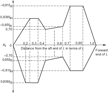
Figure 2.2.2 Shear force factor
Kf
2.6 Buckling strength
2.6.4 The
shear buckling requirements of Pt 3, Ch 4, 7.3 Elastic critical buckling stress are to be applied.
Table 2.2.1 Buckling factors of safety,
λ
| Structural item
|
Buckling
factor
of safety, λ
|
| Longitudinally effective plating
|
1,0
|
| Longitudinal stiffeners
when the
buckling failure mode of the attached plating is elasto-plastic,
see Note
|
1,1
|
| Longitudinal stiffeners
when the
buckling failure mode of the attached plating is elastic, see Note
|
1,25
|
Note The buckling mode of failure of the attached plating is
defined as follows:
|
|
|
elastic
|
σE ≤ 0,5 σo
|
|
|
elasto-plastic
|
σE > 0,5 σo
|
where
Note
|
σo
|
= |
specified minimum yield stress, in
N/mm2. |
|
|