
Section
8 Double bottom structure
8.1 General
8.1.1 The
double bottom is, in general, to be longitudinally framed, but special
consideration will be given to proposals for a transverse framing
system.
8.1.4 The
requirements given in Pt 4, Ch 7, 8.8 Allowable hold loading in the flooded condition are
to be applied to bulk carriers which satisfy the following criteria:
- Single skin construction, or double skin construction where any
part of the longitudinal bulkhead is located within B/5 or 11,5 m,
whichever is less, inboard from the ship’s side at right angles
to the centreline at the assigned summer load line.
- Length, L, of 150 m or above.
- Intended for the carriage of cargoes having bulk densities of
1,0 tonne/m3 or above.
8.1.5 For
all bulk carriers where bulk cargoes are discharged by grabs the maximum
recommended unladen weight of the grab corresponding to the approved
inner bottom plating thickness is to be calculated using the following
formulae:
where:
|
d
|
= |

|
|
P
|
= |
unladen
grab weight, in tonnes |
|
s
|
= |
spacing
of inner bottom longitudinal, in mm |
|
k
|
= |
higher
tensile steel factor as defined in Pt 4, Ch 7, 1.8 Symbols and definitions 1.8.1
|
|
t
|
= |
thickness
of inner bottom plating, in mm |
The maximum recommended unladen weight of the grab rounded up
to the next tonne above, is to be recorded in the Loading Manual (see
also
Pt 3, Ch 4, 8.2 Loading Manual 8.2.4.(e)),
and does not preclude the use of heavier grabs. It is intended as
an indication to the Builders, Owners and operators of the increased
risk of local damage and the possibility of accelerated diminution
of the plating thickness if grabs heavier than this are used regularly
to discharge cargo.
8.1.6 Detail
design guidelines for stiffeners connecting inner bottom and bottom
longitudinals are shown in the ShipRight FDA Procedure, Structural
Detail Design Guide (SDDG).
Table 7.8.1 Strengthening for heavy cargo
requirements
| Symbols
|
Item
|
Requirement
|
L, l
e, D, T, s, S, k, Z and t as defined in Pt 4, Ch 7, 1.8 Symbols and definitions 1.8.1
|
C
1
|
= |
a factor varying from 1,0 at  to to  at base line of ship at base line of ship |
|
C
|
= |
stowage rate, in m3/tonne, and is defined
as the volume of the hold excluding the volume contained within the
depth of the cargo hatchway divided by the weight of cargo stowed
in the hold. The value is not to be taken greater than 0,865 |
F
B as defined in Pt 3, Ch 4, 5.7 Local reduction factors
R and θ as
defined in Pt 4, Ch 7, 1.8 Symbols and definitions 1.8.1
|
H
|
= |
height from tank top, at position under
consideration, to deck at side amidships, in metres |
|
Y
1
|
= |
distance from to tank top, in metres to tank top, in metres |
|
h
0
|
= |
for plating and stiffeners the vertical distance, in
metres, from the inner bottom to the highest point of the tank
excluding hatchway |
|
b
1
|
= |
the larger horizontal distance, in metres, from the
tank corner at top of tank either side to the point of plate or
stiffener under consideration |
|
(1) Double bottom floors
|
The spacing of floors, generally, is
not to exceed 2,5 m. Scantlings are to comply with the requirements of Pt 4, Ch 1, 8.5 Floors
|
|
(2) Double bottom side girders
|
The spacing of side girders,
generally, is not to exceed 3,7 m. Scantlings are to comply with the
requirements of Pt 4, Ch 1, 8.3 Girders
|
|
(3) Inner bottom plating,
see Note 3
|
The thickness of the inner bottom plating in the holds is to
be not less than required by the greatest of the following:
(a)
 or or
(b) t = 0,00455s
 mm, or mm, or
(c) Where the double bottom tanks are interconnected with
double skin side tanks or combined hopper and topside tanks the
scantlings are also to satisfy the requirements for deep tanks in Table 1.9.1 Watertight and deep tank bulkhead
scantlings in Chapter 1,
with the load head h
4, = h
0 cos θ + Rb
1 m
(d) In way of ballast holds the scantlings are also to
satisfy the requirements for deep tanks in Table 1.9.1 Watertight and deep tank bulkhead
scantlings in Pt 4, Ch 1 General Cargo Ships, with the load head h
4, in metres, measured to the deck at centre, but see
also
Pt 3, Ch 9, 7 Bottom strengthening for loading and unloading aground if protection against heavy
grabs is desired.
|
|
(4) Inner bottom longitudinals
see Notes 1 and 2
|
The section modulus of inner bottom longitudinals is to be
not less than the greatest of the following:
(a) Z = 85 per cent of the Rule value for bottom
longitudinals as given in Table 1.6.2 Shell framing (longitudinal)
Pt 4, Ch 1 General Cargo Ships , or
(b)  cm3 or cm3 or
(c) Where the double bottom tanks are interconnected with
double skin side tanks or combined hopper and topside tanks Z =
0,0073skh
4
l
e
2 cm3 where h
4 = h
0 cos θ + Rb
1 m. Z is not to be less than the requirements for deep
tanks in Table 1.9.1 Watertight and deep tank bulkhead
scantlings in Pt 4, Ch 1 General Cargo Ships, with the load head h
4, in metres, measured to the highest point of the topside
tank, or side tank, or
(d) In way of ballast holds the section modulus of the
longitudinals is to be not less than required for deep tanks in Table 1.9.1 Watertight and deep tank bulkhead
scantlings in Pt 4, Ch 1 General Cargo Ships, with the load head h
4, in metres, measured to the deck at centre
|
Note
1. If plate girders are fitted
alternatively with built or rolled sections, the section modulus as
given in (4)(b) may be reduced by 10 per cent.
|
Note
2. Consideration will be given to the
fitting of struts in way of double bottom tanks in ships with
homogeneous loading. The arrangement and scantlings are, in general,
to be confirmed by direct calculation.
|
Note
3.
See also
Pt 4, Ch 7, 8.1 General 8.1.5 for the maximum recommended
unladen weight of the grab corresponding to the approved inner bottom
plating thickness.
|
8.2 Carriage of heavy cargoes
8.3 Carriage of heavy cargoes with specified or alternate holds empty
8.4 Ships to be classed '100A1 bulk carrier, strengthened for heavy
cargoes, any hold may be empty, ESP'
8.4.1 For
ships to be classed ‘100A1 bulk carrier, strengthened
for heavy cargoes, any hold may be empty, ESP’, the requirements
of Pt 4, Ch 7, 8.2 Carriage of heavy cargoes 8.2.1 and Pt 4, Ch 7, 8.3 Carriage of heavy cargoes with specified or alternate holds empty 8.3.1 are to be complied with. In
addition the value for C, the stowage rate in m3/tonne,
as defined in Table 7.8.1 Strengthening for heavy cargo
requirements,
is not be taken greater than 0,60 for each hold.
8.5 Ballast ducts
8.5.1 Where
ballast ducts are arranged in lieu of suction and/or filling pipes,
the scantlings will be approved as suitable for a specified equivalent
static head of water. This head must not be exceeded in service, and
details of methods to ensure this are to be submitted. The continuity
of the floors is to be maintained in way of the ducts.
8.6 Structural details in way of double bottom tank and hopper tank
knuckle
8.6.1 In all
dry holds where the double bottom tank and hopper tank knuckle is
of radiused construction and the floor spacing is 2,5 m or greater
brackets shown as in Figure 7.8.1 Intermediate brackets at knuckle are
to be arranged mid-length between floors in way of the intersection.
The brackets are to be attached to the adjacent inner bottom and hopper
longitudinals. The thickness of the brackets is to be in accordance
with Pt 4, Ch 1, 8.5 Floors 8.5.3 but need not
exceed 15 mm. This requirement does not apply where the double bottom
tank and hopper tank knuckle is of welded construction.
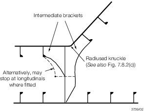
Figure 7.8.1 Intermediate brackets at knuckle
8.6.2 In way
of floodable holds, two intermediate bracket arrangements, as shown
in Figure 7.8.1 Intermediate brackets at knuckle, are to be provided
in all cases where the hopper to double bottom knuckle is radiused
and are, in general, to be located at each frame space. Where the
double bottom tank and hopper tank knuckle is of welded construction,
a single intermediate bracket arrangement, as shown in Figure 7.8.1 Intermediate brackets at knuckle, is to be provided only
when the floor spacing is greater than 2,5 m.
8.6.4 Detail
design guidelines for the connection of hopper tank sloping plating
to inner bottom plating are shown in the ShipRight FDA Procedure,
Structural Detail Design Guide (SDDG).
8.7 Combined double bottom/hopper tank and topside tank
8.7.1 Where
a double bottom/hopper tank is interconnected with a topside tank
the dimensions of the connecting trunks or pipes, and the air/overflow
pipe(s) and the type of closing appliance are to comply with the requirements
of Pt 5, Ch 13, 12 Air, overflow and sounding pipes.
8.8 Allowable hold loading in the flooded condition
8.8.2 The
maximum load which may be carried in each cargo hold in combination
with flood water is to be determined for the most severe homogeneous,
non-homogeneous and packed cargo conditions contained in the Loading
Manual. The maximum density of cargo intended to be carried in each
condition is to be used.
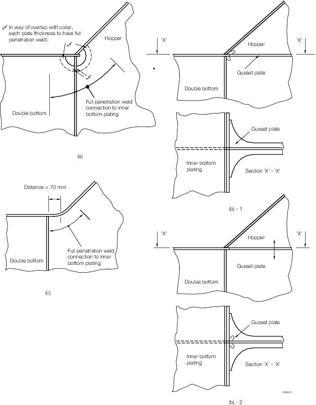
Figure 7.8.2 Connection at intersection of double bottom and hopper
8.8.3 The
ship is to be assumed immersed to the draught, TF, in metres,
in way of the flooded cargo hold under consideration. The flooding
head, hf, see
Figure 7.8.3 Loading, is to be taken as the distance, in metres, measured
vertically with the ship in the upright position, from the inner bottom
to position, df, in metres, from the baseline given by:
-
In general:
-
d
f = D for the foremost hold
-
d
f = 0,9D for other holds
-
For ships less
than 50 000 tonnes deadweight with Type B freeboard:
-
d
f = 0,95D for the foremost hold
-
d
f = 0,85D for other holds
where
|
D
|
= |
distance,
in metres, from the baseline to the freeboard deck at side amidships. |
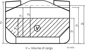
Figure 7.8.3 Loading
8.8.4 For
this application, the double bottom is defined as the structure bounded
by the transverse bulkhead lower stools (or bulkhead plating if no
lower stools are fitted) and the hopper sides. The floors and girders
immediately in way of these structures are excluded.
8.8.5 The
determination of shear strength required for the permissible load
assessment in Pt 4, Ch 7, 8.8 Allowable hold loading in the flooded condition 8.8.9, is to
be performed using the net plate thickness, tnet, for the
floors and girders:
where
|
t |
= |
as built thickness,
in mm |
|
tc
|
= |
thickness
deduction for corrosion, in mm, generally to be taken as 2,5 mm. |
8.8.6 Shear
capacity of the double bottom is defined as the sum of the shear strengths
for:
-
all the floors
adjacent to both hoppers, less one half the strength of the floors
adjacent to each lower stool (or transverse bulkhead if no lower stool
is fitted), see
Figure 7.8.4 Double bottom structure, and
-
all the girders
adjacent to the lower stools (or transverse bulkheads if no lower
stool is fitted).
Where a girder or floor terminates without direct attachment
to the boundary stool or hopper side girder, its shear capacity is
to include only that for the effectively connected end.
8.8.7 The
shear strengths, S
f1, of floors adjacent to
hoppers, and S
f2, of floors in way of openings
in bays nearest to the hoppers, are as follows:
|
Sf2
|
= |
0,001 Af,h τp/η2 kN |
where
|
A
f
|
= |
net sectional area, in mm2, of floor panel adjacent
to hopper
|
|
A
f,h
|
= |
net sectional area, in mm2, of floor panel in way
of opening in the bay closest to hopper
|
|
η1
|
= |
1,10 |
|
η2
|
= |
1,20
generally |
|
|
= |
1,10 where appropriate
reinforcement is fitted in way of the opening |
|
σ0
|
= |
specified minimum yield stress, in N/mm2
|
|
τp
|
= |
permissible
shear stress, to be taken equal to the lesser of: |
|
τ0
|
= |

|
|
τc
|
= |

|
where
|
s1
|
= |
spacing
of stiffening members, in mm, for the panel under consideration |
|
tnet
|
= |
net
thickness, in mm, of the panel under consideration. |
For floors adjacent to the stools (or bulkhead plating if no lower stools
are fitted), τp may be taken as  N/mm2. N/mm2.
8.8.8 The
shear strengths S
g1, of girders adjacent to
transverse bulkhead lower stools (or transverse bulkheads if no lower
stools are fitted), and S
g2, of girders in
way of the largest openings in bays nearest to the lower stools (or
transverse bulkheads if no lower stools are fitted), are as follows:
|
S
g2
|
= |
0,001 Ag,h τp/η2 kN |
where
|
A
g
|
= |
net sectional area, in mm2, of the girder adjacent
to transverse bulkhead lower stool (or transverse bulkhead, if no
lower stool is fitted)
|
|
A
g,h
|
= |
net sectional area, in mm2, of the girder in way
of the largest openings in the bays closest to the transverse bulkhead
lower stool (or transverse bulkhead if no lower stool is fitted)
|
|
η1
|
= |
1,10 |
|
η2
|
= |
1,15
generally |
|
|
= |
1,10 where appropriate
reinforcement is fitted in way of the opening. |
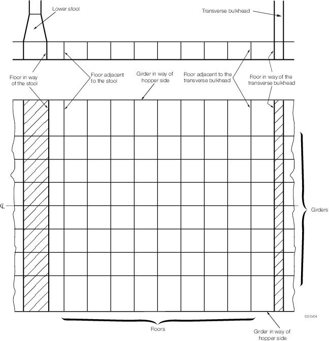
Figure 7.8.4 Double bottom structure
8.8.9 The
permissible cargo hold loading, W
p, is given
by:
where
|
d
f, D
|
= |
as defined in Pt 4, Ch 7, 8.8 Allowable hold loading in the flooded condition 8.8.3
|
|
g
|
= |
gravitational
constant, 9,81 m/sec2
|
|
h
f
|
= |
flooding head, in metres, as defined in Pt 4, Ch 7, 8.8 Allowable hold loading in the flooded condition 8.8.3
|
|
h
1
|
= |
 where Y is in kN/m2 where Y is in kN/m2
|
|
n |
= |
number of floors
between transverse bulkhead lower stools or transverse bulkheads,
if no lower stools are fitted |
|
s
|
= |
spacing,
in metres, of double bottom longitudinals adjacent to hoppers |
|
A
DB,e
|
= |


|
|
A
DB,h
|
= |


|
|
B
DB
|
= |
breadth of double bottom, in metres, between hoppers see
Figure 7.8.5 Double bottom breadth
|
|
B
DB,h
|
= |
distance, in metres, between openings see
Figure 7.8.5 Double bottom breadth
|
|
B
DB,i
|
= |
(B
DB-s) for floors where
shear strength is given by Sf1
|
|
|
= |
B
DB,h for floors where shear strength is given by Sf2
|
|
C
e
|
= |
shear capacity of the double bottom, in kN (tonne- f), as defined
in Pt 4, Ch 7, 8.8 Allowable hold loading in the flooded condition 8.8.6, considering for
each floor, the shear strength S
f1, see
Pt 4, Ch 7, 8.8 Allowable hold loading in the flooded condition 8.8.7, and for each girder, the
lesser of the shear strengths S
g1 and S
g2, see
Pt 4, Ch 7, 8.8 Allowable hold loading in the flooded condition 8.8.8
|
|
C
h
|
= |
shear capacity of the double bottom, in kN (tonne- f), as defined
in Pt 4, Ch 7, 8.8 Allowable hold loading in the flooded condition 8.8.6, considering for
each floor, the lesser of the shear strengths S
f1 and S
f2, see
Pt 4, Ch 7, 8.8 Allowable hold loading in the flooded condition 8.8.7, and for each girder, the lesser of the shear strengths S
g1 and Sg2, see
Pt 4, Ch 7, 8.8 Allowable hold loading in the flooded condition 8.8.8
|
|
F
c
|
= |
1,1 in general |
|
|
= |
1,05 for steel
mill products |
|
S
i
|
= |
spacing of ith floor, in metres
|
|
T
F
|
= |
d
f - 0,1D
|
|
V
|
= |
volume,
in m3, occupied by cargo at a level h
1
|
|
X
|
= |
the
lesser of X
1 and X
2 for
bulk cargoes and
|
|
X
|
= |
X
1 for steel mill products
|
where
|
X
1
|
= |
 where Y is in kN/m2 where Y is in kN/m2
|
|
X
2
|
= |
Y + ρ g (TF - h
f μ) where Y is in kN/m2
|
|
Y
|
= |
the
lesser of Y
1 and Y
2 given
by:
|
|
Y
1
|
= |

|
|
Y
2
|
= |

|
|
μ |
= |
permeability
of cargo but need not exceed 0,3 |
|
|
= |
0,0 for steel mill
products |
|
ρ |
= |
density of
sea water, 1,025 tonne/m3
|
|
ρc
|
= |
cargo
density, in tonne/m3 (bulk density for bulk cargoes and
actual cargo density for steel mill products).
|
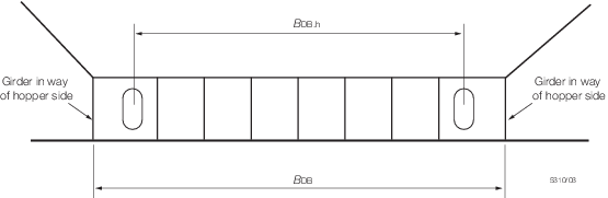
Figure 7.8.5 Double bottom breadth
|