
Section
8 Headers
8.1 Circular section headers
8.2 Rectangular section headers
8.2.1 The thickness of the flat walls of rectangular section headers is to be
determined at the centre of the sides, at all the lines of holes and at the corners. The
minimum required is to be the greatest thickness determined by the following
formula:
where
t, p and σ are as defined in Pt 5, Ch 10, 1.2 Definition of symbols
|
n
|
= |
one half of the internal width of the wall perpendicular to that
under consideration, in mm, see
Figure 10.8.1 Rectangular section
headers
|
|
J
|
= |
ligament efficiency for membrane stresses determined in accordance
with Pt 5, Ch 10, 8.2 Rectangular section headers 8.2.3
|
|
J
1
|
= |
ligament efficiency for bending stresses determined in accordance
with Pt 5, Ch 10, 8.2 Rectangular section headers 8.2.3
|
|
Y
|
= |
a coefficient determined in accordance with Pt 5, Ch 10, 8.2 Rectangular section headers 8.2.2. In all cases if the value of Y is
negative, the sign is to be ignored
c is defined in Pt 5, Ch 10, 1.2 Definition of symbols
|
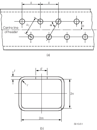
Figure 10.8.1 Rectangular section
headers
8.2.2 The
coefficient Y for use in Pt 5, Ch 10, 8.2 Rectangular section headers 8.2.1 is to be determined as follows:
-
at the centre
of the side with internal width, 2 m:
-
at a line of
holes parallel to the longitudinal axis of the header on the wall
of width, 2 m:
-
to check the
effect of the off-set on a staggered hole arrangement where the holes
are positioned equidistant from the centreline of the wall:
-
at the corners:
8.2.5 In
the case of elliptical holes the value of d to be used
in the equations for J and J
1 is
to be the inside dimension of the hole measured parallel to the longitudinal
axis of the header. For evaluating the two limiting values of d in
the equations for J
1, the value of d is
to be the inside dimension of the hole measured perpendicular to the
longitudinal axis of the header.
8.2.6 The
internal corner radius, r, is to be not less than one
third of the mean of the nominal thicknesses of the two sides, but
in no case to be less than 6,5 mm.
8.3 Toroidal furnace headers
8.3.1 The
minimum thickness of a toroidal header forming the lower end of a
waterwall furnace, and supporting the weight of the boiler and water,
is to be determined by the following formula:
where
|
W
|
= |
imposed
loading on each water wall tube due to the weight of the boiler and
water, in N |
|
d
|
= |
minimum
diameter of the tube hole in the toroid, in mm |
The calculation is to be performed at design pressure using
the allowable stress at saturation temperature, and also at zero pressure
using the allowable stress at 100°C.
8.4 Header ends
8.4.1 The
shape and thickness of ends forged integrally with the bodies of headers
are to be the subject of special consideration.
8.4.2 Where
sufficient experience of previous satisfactory service of headers
with integrally forged ends cannot be shown, the suitability of a
proposed form of end is to be proved in accordance with the provisions
of Pt 5, Ch 10, 1.10 Pressure parts of irregular shape.
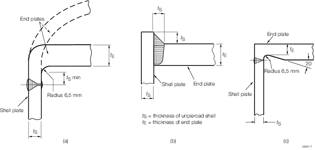
Figure 10.8.2 Typical methods of attachment of header end closures
8.4.3 Ends
attached by welding are to be designed as follows:
- Dished ends: these are to be in accordance with Pt 5, Ch 10, 4.1 Minimum thickness.
- Flat ends: the minimum thickness of flat end plates is to be determined
by the following formula:
|
C
|
= |
0,019
for circular headers |
|
|
= |
0,032 for rectangular
headers. |
|
C
|
= |
0,028
circular headers |
|
|
= |
0,040 for rectangular
headers. |
8.4.4 Where
flat end plates are bolted to flanges attached to the ends of headers,
the flanges and end plates are to be in accordance with recognised
pipe flange standards.
8.4.5 Openings
in flat plates are to be compensated in accordance with Figure 10.2.9 Compensation for welded standpipes or branches in cylindrical shells, with the
value of A
1 the compensation required, calculated
as follows:
where
|
d
o
|
= |
diameter of hole in flat plate, in mm |
|
t
f
|
= |
required thickness of the flat plate in the area under consideration,
in mm, calculated in accordance with Pt 5, Ch 10, 8.4 Header ends 8.4.3 or Pt 5, Ch 10, 9.1 Stayed flat surfaces 9.1.6, as applicable,
without corrosion allowance
|
|
Limit D
|
= |
0,5 d
o.
|
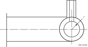
Figure 10.8.3 Toroidal furnace headers
|