
Section
2 Carbon and low alloy steels
2.1 Carbon and low alloy steel pipes, valves and fittings
2.1.2 Materials for Class III piping systems are to be manufactured and tested in
accordance with the requirements of acceptable national specifications. Pipes having
forge butt welded longitudinal seams are not to be used for fuel oil systems, for
heating coils in oil tanks, or for pressures exceeding 0,4 MPa. The manufacturer's
certificate will be acceptable and is to be provided for each consignment of material.
See
Ch 1, 3.1 General 3.1.3.(c) of the Rules for the Manufacture, Testing and Certification of Materials, July 2022.
2.2 Wrought steel pipes and bends
2.2.1 The
maximum permissible design stress, σ, is to be taken as the
lowest of the following values:
where
|
E
t
|
= |
specified minimum lower yield or 0,2 per cent proof stress at
the design temperature; in the case of stainless steel, the 1,0 per
cent proof stress at design temperature is to be used |
|
R
20
|
= |
specified minimum tensile strength at ambient temperature |
|
S
R
|
= |
average stress to produce rupture in 100 000 hours at the design
temperature |
Values of the maximum permissible design stress, σ, obtained
from the properties of the steels specified in Ch 6 Steel Pipes and Tubes of the Rules for Materials are shown in Table 12.2.1 Carbon and carbon-manganese steel
pipes and Table 12.2.2 Alloy steel pipes. For intermediate values
of specified minimum strengths and temperatures, values of the permissible
design stress may be obtained by interpolation.
2.2.2 Where
it is proposed to use, for high temperature service, alloy steels
other than those detailed in Table 12.2.2 Alloy steel pipes particulars of the tube sizes, design conditions and
appropriate national or proprietary material specifications are to
be submitted for consideration.
Table 12.2.1 Carbon and carbon-manganese steel
pipes
Specified minimum tensile strength, N/mm2
(kgf/mm2)
|
Maximum permissible stress, N/mm2
(kgf/cm2)
|
|
|
Maximum design temperature, °C
|
| 50
|
100
|
150
|
200
|
250
|
300
|
320
(33)
|
|
107
(1091)
|
105
(1070)
|
99
(1010)
|
92
(938)
|
78
(795)
|
62
(632)
|
360
(37)
|
|
120
(1224)
|
117
(1193)
|
110
(1122)
|
103
(1050)
|
91
(928)
|
76
(775)
|
410
(42)
|
|
136
(1387)
|
131
(1336)
|
124
(1264)
|
117
(1193)
|
106
(1081)
|
93
(948)
|
460
(47)
|
|
151
(1540)
|
146
(1489)
|
139
(1417)
|
132
(1346)
|
122
(1244)
|
111
(1132)
|
490
(50)
|
|
160
(1632)
|
156
(1591)
|
148
(1509)
|
141
(1438)
|
131
(1336)
|
121
(1234)
|
|
|
Maximum design temperature, °C
|
| 350
|
400
|
410
|
420
|
430
|
440
|
450
|
320
(33)
|
57
(581)
|
55
(561)
|
55
(561)
|
54
(551)
|
54
(551)
|
54
(551)
|
49
(500)
|
360
(37)
|
69
(704)
|
68
(693)
|
68
(693)
|
68
(693)
|
64
(653)
|
56
(571)
|
49
(500)
|
410
(42)
|
86
(877)
|
84
(857)
|
79
(806)
|
71
(724)
|
64
(653)
|
56
(571)
|
|
460
(47)
|
101
(1030)
|
99
(1010)
|
98
(999)
|
85
(876)
|
73
(744)
|
62
(632)
|
53
(540)
|
490
(50)
|
111
(1132)
|
109
(1111)
|
98
(999)
|
85
(867)
|
73
(744)
|
62
(632)
|
53
(540)
|
Table 12.2.2 Alloy steel pipes
| Type of
steel
|
Specified
minimum tensile strength, N/mm2 (kgf/mm2)
|
Maximum permissible stress, N/mm2 (kgf/cm2)
|
| Maximum design temperature, °C
|
| 50
|
100
|
200
|
300
|
350
|
400
|
440
|
450
|
460
|
470
|
| 1 Cr 1/2 Mo
|
440
(46)
|
159
(1621)
|
150
(1530)
|
137
(1397)
|
114
(1162)
|
106
(1081)
|
102
(1040)
|
101
(1030)
|
101
(1030)
|
100
(1020)
|
99
(1010)
|
| 2 1/4 Cr 1 Mo annealed
|
410
(42)
|
76
(775)
|
67
(683)
|
57
(581)
|
50
(510)
|
47
(479)
|
45
(459)
|
44
(449)
|
43
(438)
|
43
(438)
|
42
(428)
|
2 1/4 Cr 1
Mo
normalised and tempered
see Note 1
|
490 (50)
|
167
(1703)
|
163
(1662)
|
153
(1550)
|
144
(1468)
|
140
(1428)
|
136
(1387)
|
130
(1326)
|
128
(1305)
|
127
(1295)
|
116
(1183)
|
2 1/4 Cr 1
Mo
normalised and tempered
see Note
2
|
490 (50)
|
167
(1703)
|
163
(1662)
|
153
(1560)
|
144
(1468)
|
140
(1428)
|
136
(1387)
|
130
(1326)
|
122
(1244)
|
114
(1162)
|
105
(1071)
|
| 1/2 Cr 1/2 Mo 1/4
V
|
460
(47)
|
166
(1693)
|
162
(1652)
|
147
(1499)
|
120
(1224)
|
115
(1173)
|
111
(1132)
|
106
(1081)
|
105
(1071)
|
103
(1050)
|
102
(1040)
|
|
|
|
Maximum design temperature, °C
|
| 480
|
490
|
500
|
510
|
520
|
530
|
540
|
550
|
560
|
570
|
| 1 Cr 1/2 Mo
|
440
(46)
|
98
(999)
|
97
(989)
|
91
(928)
|
76
(775)
|
62
(632)
|
51
(520)
|
42
(428)
|
34
(347)
|
27
(275)
|
22
(224)
|
| 2 1/4 Cr 1 Mo annealed
|
410 (42)
|
42
(428)
|
42
(428)
|
41
(418)
|
41
(418)
|
41
(418)
|
40
(408)
|
40
(408)
|
40
(408)
|
37
(377)
|
32
(326)
|
2 1/4 Cr 1
Mo
normalised and tempered
see Note 1
|
490 (50)
|
106
(1081)
|
96
(979)
|
86
(877)
|
76
(775)
|
67
(683)
|
58
(591)
|
49
(500)
|
43
(438)
|
37
(377)
|
32
(326)
|
2 1/4 Cr 1
Mo
normalised and tempered
see Note 2
|
490
(50)
|
96
(979)
|
88
(897)
|
79
(806)
|
72
(734)
|
64
(653)
|
56
(571)
|
49
(500)
|
43
(438)
|
37
(377)
|
32
(326)
|
| 1/2 Cr 1/2 Mo 1/4 V
|
460 (47)
|
101
(1030)
|
99
(1010)
|
97
(989)
|
94
(959)
|
82
(836)
|
72
(734)
|
62
(632)
|
53
(540)
|
45
(459)
|
37
(377)
|
Note
1. Maximum permissible stress values
applicable when the tempering temperature does not exceed 750 °C.
Note
2. Maximum permissible stress values
applicable when the tempering temperature exceeds 750 °C.
|
2.2.3 The
minimum thickness, t, of straight steel pipes is to be
determined by the following formula:
For pipes passing through tanks, an additional corrosion allowance
is to be added to take account of external corrosion; the addition
will depend on the external medium and the value is to be in accordance
with Table 12.2.3 Values of c for steel pipes . Where
the pipes are efficiently protected, the corrosion allowance may be
reduced by not more than 50 per cent.
Table 12.2.3 Values of c for steel pipes
| Piping service
|
c
mm
|
| Superheated steam systems
|
0,3
|
| Saturated steam systems
|
0,8
|
| Steam coil systems in cargo
tanks
|
2,0
|
| Feed water for boilers in open
circuit systems
|
1,5
|
| Feed water for boilers in closed
circuit systems
|
0,5
|
| Blow down (for boilers)
systems
|
1,5
|
| Compressed air systems
|
1,0
|
| Hydraulic oil systems
|
0,3
|
| Lubricating oil systems
|
0,3
|
| Fuel oil systems
|
1,0
|
| Cargo oil systems
|
2,0
|
| Refrigerating plants
|
0,3
|
| Fresh water systems
|
0,8
|
| Sea-water systems in general
|
3,0
|
2.2.4 The
minimum thickness, t
b, of a straight steel
pipe to be used for a pipe bend is to be determined by the following
formula, except where it can be demonstrated that the use of a thickness
less than t
b would not reduce the thickness
below t at any point after bending:
2.2.6 For
sounding pipes, except those for cargo tanks with cargo having a flash
point of less than 60°C, the minimum thickness is intended to
apply to the part outside the tank.
2.2.7 For
air, bilge, ballast, fuel, overflow, sounding and venting pipes as
listed in Table 12.2.4 Minimum thickness for steel
pipes, where
the pipes are efficiently protected against corrosion, the thickness
may be reduced by not more than 1 mm.
Table 12.2.4 Minimum thickness for steel
pipes
External
diameter, D,
in mm
|
Pipes in
general,
in mm
|
Venting, overflow
and sounding pipes for structural tanks,
in mm
|
Bilge, ballast and
general sea-water pipes,
in mm
|
Bilge, air,
overflow and sounding pipes through ballast and fuel tanks, ballast lines
through fuel tanks and fuel lines through ballast tanks,
in
mm
|
Air, overflow and
sounding pipes for fuel oil tanks passing through cargo holds of bulk
carriers, in mm
|
10,2-12
13,5-19
20
21,3-25
26,9-33,7
|
1,6
1,8
2,0
2,0
2,0
|
-
-
-
-
-
|
-
-
-
3,2
3,2
|
-
-
-
-
-
|
-
-
-
-
-
|
38-44,5
48,3
51-63,5
70
76,1-82,5
|
2,0
2,3
2,3
2,6
2,6
|
4,5
4,5
4,5
4,5
4,5
|
3,6
3,6
4,0
4,0
4,5
|
6,3
6,3
6,3
6,3
6,3
|
-
-
6,3
6,3
7,6
|
88,9-108
114,3-127
133-139,7
152,4-168,3
177,8
|
2,9
3,2
3,6
4,0
4,5
|
4,5
4,5
4,5
4,5
5,0
|
4,5
4,5
4,5
4,5
5,0
|
7,1
8,0
8,0
8,8
8,8
|
8,0
8,8
8,8
8,8
8,8
|
193,7
219,1
244,5-273
298,5-368
406,4-457,2
|
4,5
4,5
5,0
5,6
6,3
|
5,4
5,9
6,3
6,3
6,3
|
5,4
5,9
6,3
6,3
6,3
|
8,8
8,8
8,8
8,8
8,8
|
8,8
12,5
12,5
12,5
12,5
|
Note The pipe diameters and wall thicknesses given in the
Table are based on common International Standards. Diameter and
thickness according to other National or International Standards will
be considered.
|
2.2.9 Reinforced thickness of ballast and cargo oil piping. Ballast piping passing through
cargo tanks and cargo oil pipes passing through segregated ballast tanks, as permitted
by Regulation 19.3.6 of MARPOL Annex I, are to comply with the following
requirements.
- The pipes are to be of heavy gauge steel of minimum wall thickness
according to the Table 12.2.5 Reinforced thickness of ballast and cargo oil piping, with welded or heavy flanged joints the
number of which is to be kept to a minimum.
- Expansion bends only (not glands) are permitted in these lines within cargo tanks
for serving the ballast tanks and within ballast tanks for serving the cargo
tanks
Table 12.2.5 Reinforced thickness of ballast and cargo oil piping
| Nominal diameter
(mm)
|
Minimum wall
thickness (mm)
|
| 50
|
6,3
|
| 100
|
8,6
|
| 125
|
9,5
|
| 150
|
11,0
|
| 200 and above
|
12,5
|
2.2.10 The thicknesses shown in the above table refer to carbon steel.
2.3 Pipe joints - General
2.3.1 Joints
in pressure pipelines may be made by:
- Screwed-on or welded-on bolted flanges, see
Pt 5, Ch 12, 2.5 Screwed-on flanges and Pt 5, Ch 12, 2.6 Welded-on flanges, butt welded joints and fabricated branch pieces.
- Butt welds between pipes or between pipes and valve chests or
other fittings, see
Pt 5, Ch 12, 2.6 Welded-on flanges, butt welded joints and fabricated branch pieces.
- Socket weld joints, see
Pt 5, Ch 12, 2.8 Socket weld joints.
- Welded sleeve joints, see
Pt 5, Ch 12, 2.9 Welded sleeve joints.
- Threaded sleeve joints, see
Pt 5, Ch 12, 2.10 Threaded sleeve joints and threaded couplings
- Threaded connections, see
Pt 5, Ch 12, 2.11 Fittings having threaded end connections
- Mechanical couplings, see
Pt 5, Ch 12, 2.12 Other mechanical couplings
- Special types of joints that have been shown to be suitable for the
design conditions. Details are to be submitted for consideration.
2.3.2 The
dimensions and materials of flanges, gaskets and bolting, and the
pressure − temperature rating of bolted flanges in pressure
pipelines, are to be in accordance with National or other established
Standards.
2.3.3 With
the welded pressure piping systems referred to in Pt 5, Ch 12, 2.3 Pipe joints - General 2.3.1 it is desirable that a few
flanged joints be provided at suitable positions to facilitate installation,
cold `pull up' and inspection at Periodical Surveys.
2.3.4 Piping
with joints is to be adequately adjusted, aligned and supported. Supports
or hangers are not to be used to force alignment of piping at the
point of connection.
2.3.5 Pipes
passing through, or connected to, watertight decks are to be continuous
or provided with an approved bolted or welded connection to the deck
or bulkhead.
2.3.6 Consideration
will be given to accepting joints in accordance with a recognised
National Standard which is applicable to the intended service and
media conveyed.
2.4 Steel pipe flanges
2.4.1 Flanges
may be cut from plates or may be forged or cast. The material is to
be suitable for the design temperature. Flanges may be attached to
the pipes by screwing and expanding or by welding. Alternative methods
of flange attachment may be accepted provided details are submitted
for consideration.
2.4.2 Flange
attachments to pipes and pressure − temperature ratings in accordance
with National or other approved Standards will be accepted.
2.5 Screwed-on flanges
2.5.1 Where
flanges are secured by screwing, as indicated in Figure 12.2.1 Screwed-on flange, the pipe and flange
are to be screwed with a vanishing thread and the diameter of the
screwed portion of the pipe over the thread is not to be appreciably
less than the outside diameter of the unscrewed pipe. After the flange
has been screwed hard home the pipe is to be expanded into the flange.
2.5.2 The
vanishing thread on a pipe is to be not less than three pitches in
length, and the diameter at the root of the thread is to increase
uniformly from the standard root diameter to the diameter at the top
of the thread. This may be produced by suitably grinding the dies,
and the flange should be tapered out to the same formation.
Figure 12.2.1 Screwed-on flange
2.5.3 Such screwed and expanded flanges may be used for steam for a maximum design
pressure of 3 MPa and a maximum design temperature of 370°C and for feed for a maximum
design pressure of 5 MPa.
2.6 Welded-on flanges, butt welded joints and fabricated branch pieces
2.6.1 The
types of welded-on flanges are to be suitable for the pressure, temperature
and service for which the pipes are intended.
2.6.2 Typical
examples of welded-on flange attachments are shown in Figure 12.2.2 Typical welded-on flanges, and limiting design
conditions for flange types (a) to (f) are shown in Table 12.2.6 Limiting design conditions for
flange types.
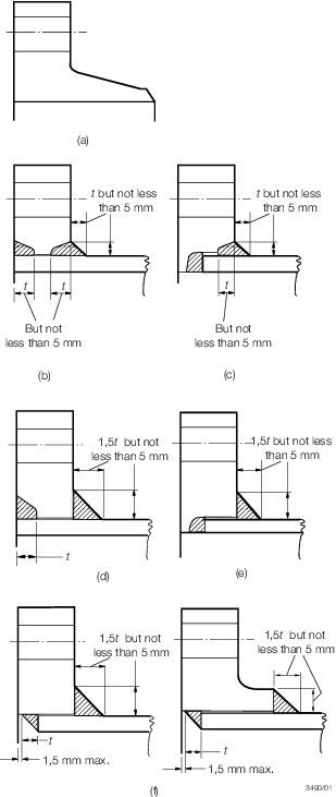
Figure 12.2.2 Typical welded-on flanges
Table 12.2.6 Limiting design conditions for
flange types
| Flange type
|
|
Maximum
pressure
|
|
Maximum
temperature,
|
Maximum pipe
o.d.,
|
Minimum pipe
bore,
|
|
|
|
|
|
in °C
|
in mm
|
in mm
|
| (a)
|
Pressure-temperature ratings to be in accordance with a Recognised
Standard
|
No restriction
|
No restriction
|
No restriction
|
| (b)
|
Pressure-temperature ratings to be in accordance with a Recognised
Standard
|
No restriction
|
168,3 for alloy
steels*
|
No restriction
|
| (c)
|
Pressure-temperature ratings to be in accordance with a Recognised
Standard
|
No restriction
|
168,3 for alloy
steels*
|
75
|
| (d)
|
Pressure-temperature ratings to be in accordance with a Recognised
Standard
|
425
|
No restriction
|
No restriction
|
| (e)
|
Pressure-temperature ratings to be in accordance with a Recognised
Standard
|
425
|
No restriction
|
75
|
| (f)
|
Pressure-temperature ratings to be in accordance with a Recognised
Standard
|
425
|
No restriction
|
No restriction
|
| * No restriction for
carbon steels
|
2.6.3 Butt
welded joints are generally to be of the full penetration type and
are to meet the requirements of Pt 5, Ch 13 Ship Piping Systems of the Rules for Materials.
2.6.4 Welded-on
flanges are not to be a tight fit on the pipes. The maximum clearance
between the bore of the flange and the outside diameter of the pipe
is to be 3 mm at any point, and the sum of the clearances diametrically
opposite is not to exceed 5 mm.
2.6.5 Where
butt welds are employed in the attachment of flange type (a), in pipe-to-pipe
joints or in the construction of branch pieces, the adjacent pieces
are to be matched at the bores. This may be effected by drifting,
roller expanding or machining, provided that the pipe wall is not
reduced below the designed thickness. If the parts to be joined differ
in wall thickness, the thicker wall is to be gradually tapered to
the thickness of the thinner at the butt joint. The welding necks
of valve chests are to be sufficiently long to ensure that the valves
are not distorted as the result of welding and subsequent heat treatment
of the joints.
2.6.6 Where
backing rings are used with flange type (a) they are to fit closely
to the bore of the pipe and should be removed after welding. The rings
are to be made of the same material as the pipes or of mild steel
having a sulphur content not greater than 0,05 per cent.
2.6.7 Branches
may be attached to pressure pipes by means of welding provided that
the pipe is reinforced at the branch by a compensating plate or collar
or other approved means, or, alternatively, that the thickness of
pipe and branch is increased to maintain the strength of the pipe.
These requirements also apply to fabricated branch pieces.
2.6.8 Welding
may be carried out by means of the shielded metal arc, inert gas metal
arc, oxy-acetylene or other approved process, but in general oxy-acetylene
welding is suitable only for flange type (a) and is not to be applied
to pipes exceeding 100 mm diameter or 9,5 mm thick. The welding is
to be carried out in accordance with the appropriate paragraphs of Pt 5, Ch 17 Requirements for Fusion Welding of Pressure Vessels and Piping.
2.7 Loose flanges
2.7.1 Loose
flange designs as shown in Figure 12.2.3 Loose flange arrangements may be used provided they are in accordance with a recognised
National or International Standard.
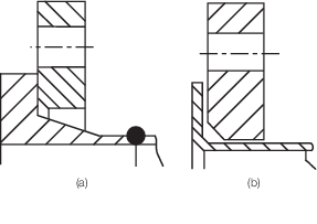
Figure 12.2.3 Loose flange arrangements
2.8 Socket weld joints
2.8.1 Socket weld joints may be used in Class III systems with carbon steel pipes
of any outside diameter. Socket weld fittings are to be of forged steel and the material
is to be compatible with the associated piping. In particular cases, socket weld joints
may be permitted for piping systems of Class I and II having outside diameter not
exceeding 88,9 mm. Such joints are not to be used where fatigue, severe erosion or
crevice corrosion is expected to occur or where toxic or asphyxiating media are
conveyed, other than for carbon dioxide fire-extinguishing distribution piping, see
also
Pt 5, Ch 10, 14.4 Welded-on flanges, butt welded joints and fabricated branch pieces 14.4.9.
2.8.3 The
leg lengths of the fillet weld connecting the pipe to the socket weld
fitting are to be such that the throat dimension of the weld is not
less than the nominal thickness of the pipe or tube.
2.9 Welded sleeve joints
2.9.1 Welded
sleeve joints may be used in Class III systems with carbon steel pipes
of any outside diameter. In particular cases, welded sleeve joints
may be permitted for piping systems of Class I and II having outside
diameter not exceeding 88,9 mm. Such joints are not to be used where
fatigue, severe erosion or crevice corrosion is expected to occur
or where toxic or asphyxiating media, other than for carbon dioxide
fire-extinguishing distribution piping, are conveyed.
2.9.2 Welded
sleeve joints are not to be used in the following locations:
- Bilge pipes in way of deep tanks.
- Cargo oil piping outside of the cargo area for bow or stern loading/discharge.
- Air and sounding pipes passing through cargo tanks.
2.9.3 Welded
sleeve joints may be used in piping systems for the storage, distribution
and utilisation of fuel oil, lubricating or other flammable oil systems
in machinery spaces provided they are located in readily visible and
accessible positions. See also
Pt 5, Ch 14, 2.9 Precautions against fire 2.9.2.
2.9.5 Welded
sleeve joints are not to be used at deck/bulkhead penetrations that
require continuous pipe lengths.
2.9.6 Welded sleeve joints are not to be used below the bulkhead deck in scupper pipes as
detailed in Pt 3, Ch 12, 4.2 Closing appliances 4.2.6 unless the scupper pipes are provided with an
automatic non-return valve at the shell. Where this is not practical, welded sleeve
joints may be accepted provided that they are kept to a minimum and located as close as
possible to the underside of the bulkhead deck.
2.9.7 The thickness of the sleeve is to satisfy the requirements of Pt 5, Ch 12, 2.2 Wrought steel pipes and bends 2.2.3 and Table 12.2.4 Minimum thickness for steel
pipes but is to be not less than 1,42 times the
nominal thickness of the pipe in order to satisfy the throat thickness requirement in
Pt 5, Ch 12, 2.9 Welded sleeve joints 2.9.8. The radial clearance between the outside diameter
of the pipe and the internal diameter of the sleeve is not to exceed 1 mm for pipes up
to a nominal diameter of 50 mm, 2 mm for pipes up to a nominal diameter of 200 mm and 3
mm for pipes of larger nominal diameter. The pipe ends are to be separated by a
clearance of approximately 2 mm at the centre of the sleeve.
2.9.8 The
sleeve material is to be compatible with the associated piping and
the leg lengths of the fillet weld connecting the pipe to the sleeve
are to be such that the throat dimension of the weld is not less than
the nominal thickness of the pipe or tube.
2.9.9 The
minimum length of the sleeve is to conform to the following formula:
2.10 Threaded sleeve joints and threaded
couplings
2.10.1 Threaded sleeve joints and threaded couplings, in accordance with National
or other established Standards, may be used with carbon steel pipes within the limits
given in Table 12.2.7 Limiting design conditions for
threaded sleeve joints and threaded couplings. Such joints are not to be used where fatigue,
severe erosion or crevice corrosion is expected to occur or where flammable or toxic
media is conveyed.
Table 12.2.7 Limiting design conditions for
threaded sleeve joints and threaded couplings
| Thread type
|
Outside pipe diameter, in mm
|
|
|
Class I
|
Class II
|
Class III
|
| Tapered thread
|
<33,7
|
<60,3
|
<60,3
|
| Parallel thread
|
-
|
-
|
<60,3
|
| KEY
|
|
| -
|
Application is not
allowed
|
2.11 Fittings having threaded end connections
2.11.2 In piping systems conveying flammable or toxic liquids, consideration will be given to
instrumentation fittings having threaded connections with suitable sealing arrangements
up to a size of DN15.
2.12 Other mechanical couplings
2.12.1 Pipe unions, compression couplings, and or slip-on joints, as shown in
Figure 12.2.4 Examples of mechanical joints
(Part 1) and Figure 12.2.5 Examples of mechanical joints
(Part 2), may be used if Type Approved for the service
conditions and the intended application. The Type Approval is to be based on the results
of testing of the actual joints. The acceptable use for each service is indicated in
Table 12.2.8 Application of mechanical
joints and dependence upon the Class of piping, with
limiting pipe dimensions, is indicated in Table 12.2.9 Application of mechanical joints
depending on class of piping.
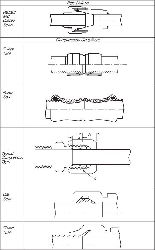
Figure 12.2.4 Examples of mechanical joints
(Part 1)
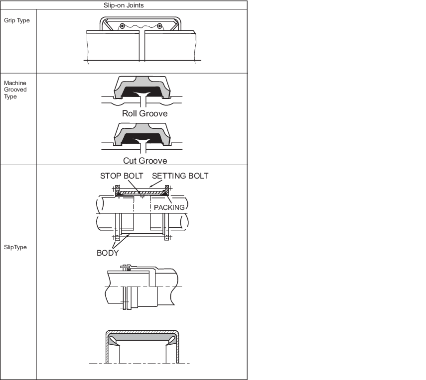
Figure 12.2.5 Examples of mechanical joints
(Part 2)
Table 12.2.8 Application of mechanical
joints
| Systems
|
Kind of connections
|
|
|
| Pipe unions
|
Compression
couplings
|
Slip-on
joints
|
Classification of
pipe system
|
Fire
endurance test condition, see Note 7
|
| Flammable fluids (flash point < 60°C)
|
| Cargo oil lines,
see Note 1
|
+
|
+
|
+
|
dry
|
30 min dry
(*)
|
| Crude oil washing
lines, see Note 1
|
+
|
+
|
+
|
dry
|
30 min dry
(*)
|
| Vent lines,
see Note 3
|
+
|
+
|
+
|
dry
|
30 min dry
(*)
|
| Inert gas
|
| Water seal effluent
lines
|
+
|
+
|
+
|
wet
|
30 min wet
(*)
|
| Scrubber effluent
lines
|
+
|
+
|
+
|
wet
|
30 min wet
(*)
|
| Main lines,
see Notes 1 & 2
|
+
|
+
|
+
|
dry
|
30 min dry
(*)
|
| Distributions
lines, see Note 1
|
+
|
+
|
+
|
dry
|
30 min dry
(*)
|
| Flammable fluids (flash point > 60°C)
|
| Cargo oil lines,
see Note 1
|
+
|
+
|
+
|
dry
|
30 min dry
(*)
|
| Fuel oil lines,
see Notes 2 & 3
|
+
|
+
|
+
|
wet
|
30 min
wet (*)
|
| Lubricating oil
lines, see Notes 2 & 3
|
+
|
+
|
+
|
wet
|
| Hydraulic oil,
see Notes 2 & 3
|
+
|
+
|
+
|
wet
|
| Thermal oil,
see Notes 2 & 3
|
+
|
+
|
+
|
wet
|
| Sea water
|
| Bilge lines,
see Note 4
|
+
|
+
|
+
|
dry/wet
|
8 min dry + 22 min
wet (*)
|
| Permanent water
filled fire‑extinguishing systems, e.g. fire main, sprinkler systems,
see Note 3
|
+
|
+
|
+
|
wet
|
30 min wet
(*)
|
| Non-permanent water
filled fire‑extinguishing systems, e.g. foam, drencher systems and fire
main, see Note 3
|
+
|
+
|
+
|
dry/wet
|
8 min dry + 22 min wet (*)
For foam systems FSS Code to be observed
|
| Ballast system,
see Note 4
|
+
|
+
|
+
|
wet
|
30 min wet
(*)
|
| Cooling water
system, see Note 4
|
+
|
+
|
+
|
wet
|
30 min wet
(*)
|
| Tank cleaning
services
|
+
|
+
|
+
|
dry
|
Fire endurance test
not required
|
| Non-essential
systems
|
+
|
+
|
+
|
dry, dry/wet,
wet
|
Fire endurance test
not required
|
| Fresh water
|
| Cooling water
system, see Note 4
|
+
|
+
|
+
|
dry
|
Fire
endurance test not required
|
| Condensate return,
see Note 4
|
+
|
+
|
+
|
dry
|
| Non-essential
system
|
+
|
+
|
+
|
dry
|
| Sanitary/drains/scuppers
|
| Deck drains
(internal), see Note 5
|
+
|
+
|
+
|
dry
|
Fire
endurance test not required
|
| Sanitary
drains
|
+
|
+
|
+
|
dry
|
| Scuppers and
discharge (overboard)
|
+
|
+
|
-
|
dry
|
| Sounding/vent
|
| Water tanks/dry
spaces
|
+
|
+
|
+
|
dry, wet
|
Fire
endurance test not required
|
| Oil tanks (f.p. >
60°C), see Notes 2 & 3
|
+
|
+
|
+
|
dry
|
| Miscellaneous
|
| Starting/control
air, see Note 4
|
+
|
+
|
-
|
dry
|
30 min dry
(*)
|
| Service air
(non-essential)
|
+
|
+
|
+
|
dry
|
Fire
endurance test not required
|
| Brine
|
+
|
+
|
+
|
wet
|
| CO2 system (outside protected space)
|
+
|
+
|
-
|
dry
|
30 min dry
(*)
|
| CO2 system (inside protected space)
|
+
|
+
|
-
|
dry
|
Mechanical joints
shall be constructed of materials with a melting point above 925°C. Ref. to
FSS Code Chapter 5.
|
| Steam
|
+
|
+
|
+ see Note 8
|
wet
|
Fire endurance test
not required
|
| Abbreviations:
+ Application is allowed.
- Application is
not allowed.
* Fire endurance test as specified in LR’s Test
Specification No. 2, Ch 5, Appendix 4 – Mechanical pipe joints – Fixed
connections, 4.2.7.
|
| If mechanical joints include any components which
readily deteriorate in case of fire, the following footnotes are to be observed:
Note
1. A fire endurance test shall be applied when mechanical joints
are installed in pump-rooms and open decks.
Note
2. Slip-on joints are not accepted inside machinery spaces of
category A or accommodation spaces. They may be accepted in other
machinery spaces provided the joints are located in easily visible and
accessible positions (refer to MSC/Circ.734).
Note
3. Mechanical joints are to be of approved fire-resistant types
except in cases where such mechanical joints are installed on open decks,
as defined in SOLAS Chapter II-2, Regulation 9.2.3.3.2.2(10), and not
used for fuel oil lines.
Note
4. A fire endurance test shall be applied when mechanical joints
are installed inside machinery spaces of category A.
Note
5. Only above bulkhead deck of passenger ships and freeboard deck
of cargo ships.
Note
7. If a connection has passed the ‘30 min dry’ test, it is
considered suitable also for applications for which the ‘8 min dry + 22
min wet’ and/or ‘30 min wet’ tests are required. If a connection has
passed the ‘8 min dry + 22 min wet’ test, it is considered suitable also
for applications for which the ‘30 min wet’ test is required.
|
Table 12.2.9 Application of mechanical joints
depending on class of piping
| Types of joints
|
Classes of piping systems
|
|
|
Class I
|
Class II
|
Class III
|
|
Pipe unions
|
|
|
|
| Welded and brazed type
|
+(OD ≤ 60,3 mm)
|
+(OD ≤ 60,3 mm)
|
+
|
|
Compression couplings
|
|
|
|
| Swage type
|
+
|
+
|
+
|
| Bite type
|
+(OD ≤ 60,3 mm)
|
+(OD ≤ 60,3 mm)
|
+
|
| Typical compression type
|
+(OD≤ 60,3mm)
|
+(OD≤ 60,3mm)
|
+
|
| Flared type
|
+(OD ≤ 60,3 mm)
|
+(OD ≤ 60,3 mm)
|
+
|
| Press type
|
-
|
-
|
+
|
|
Slip-on joints
|
|
|
|
| Machine grooved type
|
+
|
+
|
+
|
| Grip type
|
-
|
+
|
+
|
| Slip type
|
-
|
+
|
+
|
| KEY
|
| +
Application is allowed
|
| - Application is not
allowed
|
2.12.2 Where
the application of mechanical joints results in a reduction in pipe
wall thickness due to the use of bite type rings or other structural
elements, this is to be taken into account in determining the minimum
wall thickness of the pipe to withstand the design pressure.
2.12.3 Materials
of mechanical joints are to be compatible with the piping material
and internal and external media.
2.12.4 Mechanical joints for pressure pipes are to be tested to a burst pressure
of 4 times the design pressure. For design pressures above 20 MPa the required burst
pressure will be specially considered.
2.12.5 Mechanical joints, which in the event of damage could cause fire or
flooding, are not to be used in piping sections directly connected to the ship’s side
below the bulkhead deck of passenger ships and freeboard deck of cargo ships or tanks
containing flammable fluids.
2.12.6 The
mechanical joints are to be designed to withstand internal and external
pressure as applicable and where used in suction lines are to be capable
of operating under vacuum.
2.12.7 The number of mechanical joints in flammable fluid systems is to be kept to a minimum.
In general, flanged joints are to conform to a recognised standard.
2.12.8 Generally,
slip-on joints are not to be used in pipelines in cargo holds, tanks,
and other spaces which are not easily accessible. Application of these
joints inside tanks may only be accepted where the medium conveyed
is the same as that in the tanks.
2.12.9 Usage of slip type slip-on joints as the main means of pipe connection is not
permitted except for cases where compensation of axial pipe deformation is
necessary.
2.12.10 Restrained slip-on joints are permitted in steam pipes with a design
pressure of 1 MPa or less on the weather decks of oil and chemical tankers to
accommodate axial pipe movement, see
Pt 5, Ch 13, 2.7 Provision for expansion.
2.12.11 Mechanical
joints are to be tested in accordance with the test requirements of
LR’s Type Approval Test Specification Number 2, as relevant
to the service conditions and the intended application. The programme
of testing is to be agreed with LR.
2.13 Non-destructive testing
2.14 Carbon dioxide (CO2) fire-extinguishing system piping
2.14.1 The
piping for carbon dioxide fire-extinguishing systems is to comply
with the requirements of Chapter 5 - Fixed Gas Fire-Extinguishing Systems of the
FSS Code, as applicable. For purposes of Classification, any use of
the word ‘Administration’ in the Regulation is to be taken
to mean LR.
2.14.2 Where a low-pressure CO2 system is fitted, the piping system is to be
designed in such a way that the CO2 pressure at the nozzles is not less than
1 N/mm2.
2.14.3 Materials for the distribution manifolds between the carbon dioxide storage
bottles and the discharge valves to each section and associated pipes, valves and
fittings of high pressure systems are to be manufactured and tested in accordance with
the requirements for Class I piping systems. Pipes are to meet the minimum wall
thickness requirements of Table 12.2.10 Minimum thickness for steel pipes for CO2 fire-extinguishing and the manifold system is to be
hydraulically tested to a pressure of 19 MPa. A high pressure system is defined as a
system where the carbon dioxide is stored at ambient temperature.
Materials for the distribution manifolds between the carbon dioxide storage vessel(s)
and the discharge valves to each section and associated pipes, valves and fittings of
low pressure systems are to be manufactured and tested in accordance with the
requirements for Class II piping systems and the manifold system is to be hydraulically
tested to a pressure of 3,3 MPa. A low pressure system is defined as a system where the
carbon dioxide is stored at a working pressure in the range of 1,8 to 2,2 MPa.
2.14.4 Piping downstream of the distribution valve(s) for high pressure systems is
to be manufactured and tested in accordance with the requirements for Class II piping
and is to meet the minimum wall thickness requirements of Table 12.2.10 Minimum thickness for steel pipes for CO2 fire-extinguishing. After installation the distribution system
is to be leak tested at a pressure of 0,6 MPa.
Piping downstream of the
distribution valve(s) for low pressure systems is to be manufactured and tested in
accordance with the requirements for Class III piping. After installation the
distribution system is to be leak tested at a pressure of 0,6 MPa. Class III piping may
be used for open ended distribution piping downstream of the distribution valve(s) of
high pressure systems where agreed by LR and where meeting the minimum wall thickness
requirements of Table 12.2.10 Minimum thickness for steel pipes for CO2 fire-extinguishing and where a minimum of ten per cent of the
piping is hydraulically tested at a pressure of 12,5 MPa. This testing is to be carried
out before installation.
Table 12.2.10 Minimum thickness for steel pipes for CO2 fire-extinguishing
| External diameter D,
in mm
|
Minimum
thickness, in mm
|
| From bottles to distribution
station
|
From distribution station to
nozzles
|
| 21,3 - 26,9
|
3,2
|
2,6
|
| 30 - 48,3
|
4
|
3,2
|
| 51 - 60,3
|
4,5
|
3,6
|
| 63,5 - 76,1
|
5
|
3,6
|
|
|
| 82,5 - 88,9
|
5,6
|
4
|
| 101,6
|
6,3
|
4
|
| 108 - 114,3
|
7,1
|
4,5
|
| 127
|
8
|
4,5
|
|
|
| 133 - 139,7
|
8
|
5
|
| 152,4 -
168,3
|
8,8
|
5,6
|
|
|
|
|
|
Note 1. Pipes are to be galvanized at least inside, except those fitted in
the engine room where galvanizing may not be required at the discretion
of LR. Effects of galvanising shall be taken into account in the relevant
calculations e.g. volume flow.
Note 2. For threaded pipes, where allowed, the minimum wall thickness is to
be measured at the bottom of the thread.
Note 3. The external diameters and thicknesses have been selected from ISO
Recommendations R336 for smooth welded and seamless steel pipes. Diameter
and thickness according to other national or international standards may
be accepted.
Note 4. For larger diameters the minimum wall thickness will be subject to
special consideration by LR. Note 5. In general the minimum thickness is
the nominal wall thickness and no allowance need be made for negative
tolerance or reduction in thickness due to bending.
|
2.14.5 Any
part of the carbon dioxide fire-extinguishing system piping is to
be of galvanised steel or of corrosion resistant steel. Where full
penetration butt welding is used, the pipe is to be protected against
corrosion in the area of the weld seam after welding. The process
for protecting the pipe internally against corrosion is to be of an
approved type. All pipes are to be arranged to be self-draining.
Where pipes are to be led into refrigerated spaces, this is subject
to special consideration. The ends of distribution pipes downstream
of the distribution valve(s) are to extend at least 50 mm beyond the
last nozzle and are to be fitted with a dirt trap consisting of an
open ended tee with a capped nipple.
2.14.6 If it is necessary for carbon dioxide pipes to pass through accommodation
spaces, the pipe is to be seamless and is to meet the requirements for Class II pipes.
Joints are to be made only by welding and the pipes are to be hydraulically tested after
installation at a pressure of 5 MPa.
2.14.7 The
following means are permitted for making joints on carbon dioxide
fire-extinguishing system piping ;
-
Full penetration
butt welding, where the pipe is galvanised, see
Pt 5, Ch 12, 2.14 Carbon dioxide (CO2) fire-extinguishing system piping 2.14.5.
-
Couplings as
permitted by Table 12.2.8 Application of mechanical
joints.
-
Cone connections.
-
Tapered threaded joints , where allowed by Pt 5, Ch 12, 2.14 Carbon dioxide (CO2) fire-extinguishing system piping 2.14.11 and where meeting the requirements of Pt 5, Ch 12, 2.14 Carbon dioxide (CO2) fire-extinguishing system piping 2.14.11.
-
Flanged joints.
-
Socket weld
joints to acceptable National Standards and where allowed by Pt 5, Ch 12, 2.14 Carbon dioxide (CO2) fire-extinguishing system piping 2.14.8 and where meeting the requirements
of Pt 5, Ch 12, 2.14 Carbon dioxide (CO2) fire-extinguishing system piping 2.14.10.
-
Welded sleeve
joints may be used where allowed by Pt 5, Ch 12, 2.14 Carbon dioxide (CO2) fire-extinguishing system piping 2.14.9 and where meeting the requirements of Pt 5, Ch 12, 2.14 Carbon dioxide (CO2) fire-extinguishing system piping 2.14.10.
2.14.8 Socket
weld joints of an approved type may be used downstream of the distribution
valve(s), provided that the requirements for materials and limitations
on outside diameter applicable for Class II piping are applied.
2.14.9 Welded
sleeve joints of an approved type may be used within the protected
space, provided that the requirements for materials and limitations
on outside diameter applicable for Class II piping are applied.
2.14.10 Where
socket weld joints or welded sleeve joints are utilised, the pipes
in way of the welded joints are to be adequately supported and the
joints are to be located where they are visible. Where welding is
to be carried out in situ, the piping is to be kept clear
of adjacent structures to allow sufficient access for preheating and
welding, which is to be carried out in accordance with approved procedures.
2.14.11 Threaded
joints are only allowed inside the protected spaces and in carbon
dioxide bottles storage rooms. They should have no exposed screw threads
and any sealing medium should be selected as to ensure no protrusions
or debris might be produced in the pipe.
|