
Section
2 Physical conditions
2.1 Bridge and wheelhouse arrangement
2.1.1 The
bridge configuration, arrangement of consoles and equipment location
are to be such as to enable the officer of the watch to perform navigational
tasks and other functions allocated to the bridge, as well as maintain
an effective lookout. The following tasks are to be supported:
- navigation and manoeuvring;
- monitoring;
- manual steering;
- docking;
- planning;
- safety;
- communications; and
- conning.
2.1.2 Equipment
and associated displays and indicators are to be sited at clearly
defined workstations.
2.1.3 Consoles,
including the chart table, are to be positioned, so that the instrumentation
they contain is mounted in such a manner as to face a person looking
forward. As far as practicable, operating surfaces are to be normal
to the operator's line of sight.
2.1.4 From
other workstations within the wheelhouse it is to be possible to monitor
the navigation workstation and to maintain an effective lookout.
2.1.5 The
main access to the bridge is to be by means of an internal stairway.
Secondary external access is also to be provided.
2.1.6 Clear
passage of at least 700 mm width is to be available to allow movement
around the bridge with a minimum of inconvenience. Particular attention
is to be paid to the following routes which are to be as direct as
possible:
-
From bridge wing
to bridge wing, a clear passage of at least 1200 mm in width.
-
Between the internal
entrance to the bridge and the route in Pt 7, Ch 9, 2.1 Bridge and wheelhouse arrangement 2.1.6 a clear passage of at least
700 mm in width is to be provided.
-
Between adjacent
workstations, a clear passage of at least 700 mm is to be provided.
-
Between the bridge
front bulkhead or any consoles and installations placed against the
front bulkhead, to any consoles or installations placed away from
the bridge front, a clear passage of at least 800 mm is to be provided.
Space necessary for operating at a workstation is to be considered
as part of the workstation and is not to be part of the passageway.
2.1.7 The
clear height between the wheelhouse deck surface covering and the
underside of the deckhead is to be at least 2250 mm. The lower edge
of deckhead mounted equipment is to be at least 2100 mm in open areas,
passageways and at standing workstations.
2.1.8 Toilet
facilities are to be provided on the bridge or adjacent to the bridge
on the bridge deck.
2.2 Environment
2.2.1 The
bridge is to be free of physical hazards to personnel. There are to
be no sharp edges or protuberances and wheelhouse, bridge wing and
upper bridge decks are to be free of trip hazards and have non-slip
surfaces whether wet or dry.
2.2.2 Sufficient
hand-rails or equivalent are to be fitted inside the wheelhouse and
around workstations to enable personnel to move or stand safely in
bad weather. Protection of stairway openings is to be given special
consideration.
2.2.3 Provision
for seating is to be made in the wheelhouse. Means for securing the
seating are to be provided having regard to storm conditions.
2.2.4 Glare
and reflections from surfaces are to be minimised. In this respect,
walls, ceilings, consoles, chart tables and other major fittings are
to be provided with a suitable low reflective finish. Arrangements
are to be provided to prevent the obscuration of information presented
on visual display units and instruments which are fitted with transparent
covers.
2.2.5 Entrance
doors to the wheelhouse are to be securable from the inside, and operable
with one hand. Bridge wing doors are not to be self-closing, and are
to be provided with means to hold them open. For ships required to
comply with the Rules and Regulations for the Construction and
Classification of Ships for the Carriage of Liquefied Gases in Bulk,
the sealing mechanism of each door is to be such that a rapid and
efficient gas and vapour tightening can be ensured.
2.2.6 An adequate
air conditioning or mechanical ventilation system, together with sufficient
heating according to climatic conditions, is to be provided in order
to maintain the temperature of the wheelhouse within the range of
14°C to 30°C and the humidity within the range 20 per cent
to 60 per cent. The discharge of hot or cold air is not to be directed
towards bridge personnel. Control of this system is to be provided
in the wheelhouse.
2.2.7 The
noise level on the bridge is not to interfere with verbal communication,
mask audible alarm signals, or be uncomfortable to bridge personnel.
In this respect, the ambient noise level in the wheelhouse in good
weather is not to exceed 65 dB(A).
2.2.8 A sound
reception system or alternative means is to allow external sound signals
to be heard and their direction determined within the wheelhouse.
2.2.9 Permanently
installed electrical and electronic equipment is to be installed so
that electromagnetic interference does not affect the proper function
of the navigational systems and equipment. Installation of the equipment
in accordance with the guidelines and recommendations included in
IEC 60533: Electrical and electronic installations in ships
– Electromagnetic compatibility, or an acceptable equivalent
Standard, would generally be considered to meet the requirement.
2.2.10 Permanently
installed electrical and electronic equipment, on the bridge and in
the vicinity of the bridge, that is not subject to the approval required
by Pt 7, Ch 9, 3.1 Navigation workstation 3.1.13, is to have undergone
electromagnetic compatibility testing that demonstrates the equipment
satisfies the conducted and radiated emission requirements of:
- IEC 60533: Electrical and electronic installations in ships
– Electromagnetic compatibility; or
- IEC 60945: Maritime navigation and radio communication equipment
and systems – General requirements – Methods of testing
and required test results.
Testing in accordance with other appropriate standards is subject
to consideration and details are to be submitted.
2.2.11 To
demonstrate compliance with Pt 7, Ch 9, 2.2 Environment 2.2.10,
a schedule of applicable equipment is to be compiled, see
Pt 7, Ch 9, 1.2 Information and plans required to be submitted 1.2.1. Where it is proposed to add
to or modify the equipment referred to in Pt 7, Ch 9, 2.2 Environment 2.2.10 the schedule is to be maintained
accordingly, see also
Pt 7, Ch 9, 6.1 General 6.1.1. A copy of the schedule documentation is to be placed on board
the vessel and a copy is to be made available to the LR Surveyor on
request.
2.2.12 Passive
electromagnetic equipment, considered not liable to cause or be susceptible
to electromagnetic disturbances, may be provided with an exemption
statement in place of evidence of electromagnetic compatibility for
the purposes of Pt 7, Ch 9, 2.2 Environment 2.2.11. Examples
of passive electromagnetic equipment include cables, purely resistive
loads and batteries.
2.3 Lighting
2.3.1 The
level of lighting is to enable bridge personnel to perform all bridge
tasks, including maintenance and chart and office work, by day and
night. Controls, indicators, instruments, keyboards, etc. on the bridge
are to be capable of being seen in the dark, either by means of internal
lighting within the equipment or the wheelhouse lighting system. A
satisfactory level of flexibility within the lighting system is to
be available to enable the bridge personnel to adjust the lighting
in brightness and direction as required in different areas of the
bridge and by the needs of individual instruments and controls.
2.3.2 All
illumination and lighting of instruments, keyboards and controls are
to be adjustable down to zero, except the lighting of alarm and warning
indicators and the controls of dimmers which are to remain readable.
2.3.3 Two
separate circuits are to be provided for wheelhouse lighting, such
that failure of any one of the circuits does not leave the space in
darkness, see
Pt 6, Ch 2, 5.7 Lighting circuits.
2.3.5 Lighting
used in areas and at items of equipment requiring illumination, whilst
the ship is navigating, is to be such that night vision is not impaired,
e.g. red lighting. Such lighting is to be arranged, so that it cannot
be mistaken for a navigation light by another ship, and to prevent
glare and stray image reflections.
2.3.6 In order
to avoid possible confusion in colour discrimination, red lighting
is not to be fitted over chart tables.
2.3.7 To avoid
unnecessary light sources in the front area of the bridge, only instruments
necessary for the safe navigation and manoeuvring of the ship are
to be located in this area.
2.3.8 Means
are to be provided to prevent the sudden flooding of light onto the
bridge from alleyways, accommodation areas and the chart table area.
2.3.9 Deck
and superstructure lights which may impair safe navigation are to
be controlled from the bridge.
2.3.11 Means
are to be provided to test alarm and other indicator lamps.
2.4 Windows
2.4.1 All
wheelhouse windows are to be constructed of shatterproof toughened
glass having a strength commensurate with the degree of exposure of
the bridge to storm conditions and complying with a recognised National
or International Standard, e.g. ISO 21005, Ships and marine
technology – Thermally toughened safetyglass panes for windows
and side scuttles.
2.4.2 Windows
are to be as wide as possible and divisions between them are to be
kept to a minimum. No division is to be positioned immediately forward
of any workstation or on the ship's centreline.
2.4.3 To reduce
reflections from internal lighting, etc. the bridge windows are to
be inclined from the vertical plane top out, at an angle of not less
than 10° and not more than 25°. Alternative arrangements will
be specially considered.
2.4.4 The
height of the lower edge of the front windows is to allow a forward
view over the bow for a person at the navigation workstation and is
not to obstruct any of the required fields of vision, see
Pt 7, Ch 9, 2.5 Fields of vision. In this respect, the height of
the lower edge of the front windows above the deck is to be kept as
low as possible and, as far as practicable, is not to be more than
1000 mm above the deck surface.
2.4.5 The
upper edge of the front windows is to allow a forward view of the
horizon for a person with an eyeheight of 1800 mm at the conning position
when the ship is pitching in heavy seas and, as far as practicable,
is not to be less than 2000 mm above the deck surface.
2.4.6 Clear
views through the windows in front of the conning position, navigation
workstation, and, where applicable, bridge wings are to be provided
at all times regardless of weather conditions. At least two windows
are to provide such a view.
2.4.7 To ensure
a clear view in bright sunshine, sunscreens with minimum colour distortion
are to be provided. Such screens are to be readily removable and not
permanently installed. Polarised and tinted windows are not to be
fitted.
2.4.8 Heavy
duty wipers, preferably provided with an interval function and a fresh
water wash, are to be fitted.
2.4.9 Efficient
cleaning, de-icing and de-misting systems are to be fitted.
2.4.10 Suitable
safe external access arrangements fitted under the bridge windows
are to be provided to enable cleaning in the event of failure of the
above systems.
2.5 Fields of vision
2.5.1 It is
to be possible to observe all objects necessary for navigation, including
other traffic and navigation marks, in any direction from inside the
wheelhouse. In this respect there is to be a field of view around
the vessel of 360° obtained by an observer moving within the confines
of the wheelhouse.
2.5.3 Blind
sectors caused by cargo, cargo gear and other obstructions outside
the wheelhouse forward of the beam obstructing the view of the sea
surface as seen from the conning position and the navigation workstation
are not to exceed 10° each. The total arc of blind sectors is
not to exceed 20° and the clear sector between blind sectors shall
be at least 5°. However, in the view described in the preceding
paragraph, each individual blind sector is not to exceed 5°.
2.5.7 There
is to be a line of sight from the port wing to the starboard wing
through the wheelhouse.
2.5.8 The
ship's side is to be visible from the bridge wing.
2.5.9 From
workstations for functions other than navigation, the field of vision
is to enable an effective lookout to be maintained and, in this respect,
is to extend at least over an arc from 90° on the port bow, through
forward, to 22,5° abaft the beam on the starboard side, see
Figure 9.2.5 Field of view from workstation other than for navigation.
2.5.10 The
height of consoles is not to interfere with the fields of vision defined
above and is not to exceed 1350 mm.
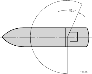
Figure 9.2.5 Field of view from workstation other than for navigation
|