
Section
6 Steel used in repairs
6.1 General
6.1.1 When renewals
are required, Surveyors should ensure that the grade of steel to be
used in the repair is in accordance with, or equivalent to, the grades
listed on the approved plans.
6.1.2 Steel used
for repair of classed ships should be manufactured, tested and certified
in accordance with the requirements of the Rules for Materials.
6.1.3 Limited quantities
of steel complying with the requirements of a national or proprietary
specification may be accepted subject to the following conditions:
-
The material is considered
equivalent to the minimum requirements of the steel grade shown on
the plan.
-
The manufacturer is
approved by LR to supply the grade of steel shown on the plan.
-
The identity stamped
on the material and the material condition clearly conform to the
details shown on the certificate.
-
Representative samples
selected for check mechanical and chemical analysis tests are satisfactory.
-
Copies of the manufacturer’s
test certificate and the results from the check tests are recorded.
6.1.5 When it is
not possible to carry out check tests before the repair is completed,
a sample should be retained for subsequent testing before departure
of the vessel. However, every effort should be made to ensure that
the material is tested before the repair is completed. The repair
is to be considered as incomplete, until such tests have been carried
out and the results confirmed as satisfactory.
6.1.8 Due to the
limited availability of Admiralty long stalk tee bars, alternative
sections may be used. Suitable alternative sections are given in Table 15.6.4 Alternatives to Admiralty long
stalk tee bars. For large scale replacement
IPN beams should be used in preference to fabricated tee bars. Where
alternative sections are used, care is to be taken to ensure a smooth
transition, using a 1 in 4 taper, between different sections. Additional
flat bar pieces of a depth not less than the flange thickness and
extending two times the web depth from the connection, may be necessary
to maintain the continuity of section modulus where the changes in
flange width or thickness between sections is large.
Table 15.6.1 Rolled plate and sections,
material grade equivalence
|
NES Specification
|
Equivalent LR
|
Equivalent international
|
| EN 10025
|
JIS G3106
|
|
-
791 - 43A
-
|
A
-
AH32
|
S235JRG2
S275J0G3
S355 JR
|
SM41B
-
SM50B
|
|
-
791 - 43D
-
|
D
-
DH32
DH36
|
S235J2G3
S275N/M
-
S355N/M
|
SM41C
-
SM50C
SM53C
|
|
791 - B
791 - BX
|
EH32
EH32 (Z Quality)
EH36
|
-
-
S355NL/ML
|
-
-
-
|
Table 15.6.2 Material and welding standard
equivalence
|
Material
|
NES Specification
|
Equivalent LR
|
| Castings
|
849 - A
|
Rules for Materials
Ch 4 Steel Castings
C- Mn (structural)
|
|
|
849 - B to G
|
Rules for Materials Ch 4 Steel Castings
|
| NAB
Castings
|
747 Pt 3
|
Rules for Materials Ch 9, 1 Castings for propellers
Grade 3 Cu3 (propellers/hull fittings)
Rules for Materials Ch 9, 2 Castings for valves, liners and bushes
Aluminium bronze (valves, liners, bushes)
|
Q1N
Plate, forgings,
castings and sections
|
736
|
none
|
| Forgings
|
848 Pt 1
848 Pt 2
|
Rules for Materials Ch 5, 2 Forgings for ship and other structural applications
Rules for Materials Ch 5, 2 Forgings for ship and other structural applications
|
| Welding
|
Hul
Machinery
|
706
DGS 9023
|
Rules for Naval Ships Vol 1, Pt 6, Ch 6 Material and Welding Requirements
Rules for Materials Ch 13 Requirements for Welded Construction
|
| Chain Cable
|
Open link
Stud link
|
176
172 - 1
172 - 2
172 - 3
|
Rules for Materials Ch 10 Equipment for Mooring and Anchoring U2
Rules for Materials Ch 10 Equipment for Mooring and Anchoring U1 forged
Rules for Materials Ch 10 Equipment for Mooring and Anchoring U2 forged
Rules for Materials Ch 10 Equipment for Mooring and Anchoring U3 forged
|
| Anchors
|
174
|
none
|
Table 15.6.3 Admiralty long stalk tee bar
sections
| Type
|
Size
Inches
|
Size
w x d
mm
|
Thickness, mm
|
Wt/m
kg
|
A
cm2
|
Inertia, Ixx
cm4
|
Height of
centroid,
mm
|
Inertia, Iyy
cm4
|
|
t
f
|
t
w1
|
t
w2
|
| 1
|
3”
|
25,4 x 76,2
|
6,4
|
4,4
|
4,4
|
3,64
|
4,64
|
27,89
|
28,2
|
0,83
|
| 2
|
4.5”
|
44,5 x 114,3
|
9,5
|
5,1
|
5,1
|
7,43
|
9,48
|
126,1
|
36,6
|
7,06
|
| 3
|
5”
|
63,5 x 127,0
|
13,4
|
6,9
|
6,4
|
12,62
|
16,13
|
248,5
|
37,6
|
25,80
|
| 4
|
6”
|
76,2 x 152,4
|
14,2
|
7,4
|
6,9
|
16,29
|
20,90
|
468,2
|
44,4
|
46,61
|
| 5
|
7”
|
88,9 x 177,8
|
15,2
|
7,9
|
7,4
|
20,44
|
26,06
|
804,9
|
51,8
|
79,49
|
| 6
|
8”
|
101,6 x 203,2
|
16,3
|
8,4
|
7,9
|
25,01
|
31,93
|
12,89
|
58,4
|
124,9
|
| 7
|
10”
|
127,0 x 254,0
|
18,3
|
9,4
|
8,9
|
35,40
|
45,35
|
28,11
|
69,3
|
273,0
|
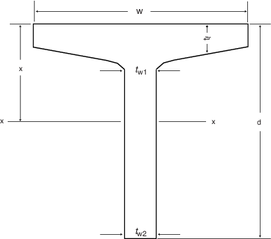
Figure 15.6.1 Standard T bar sections
Table 15.6.4 Alternatives to Admiralty long
stalk tee bars
| Type
|
Size
inches
|
IPN Series
cut
down
Beams
|
IPE Series
cut
down
Beams
|
Fabricated
web,flange
mm
|
| 1
|
3
|
IPN 100
|
IPE 120
|
75 x10
|
| 2
|
4.5
|
IPN 160
|
IPE 240
|
100 x 8,40 x 10
|
| 3
|
5
|
IPN 240
|
IPE 360
|
100 x 8,65 x 15
|
| 4
|
6
|
IPN 260
|
IPE 400
|
130 x 15,75 x 12
|
| 5
|
7
|
IPN 280
|
IPE 450
|
150 x 8,80 x 20
|
| 6
|
8
|
IPN 280
|
IPE 550A
|
180 x 8,100 x 20
|
| 7
|
10
|
IPN 320
|
IPE 600
|
220 x 10,130 x 20
|
|