
Section
1 Castings for propellers
1.1 Scope
1.1.1 This Section
gives the requirements for copper alloy castings for one-piece propellers
and separately cast blades and bosses for fixed pitch and controllable
pitch propellers (CPP). These include contra-rotating propellers
and propulsors fitted to podded drives and azimuth units.
1.1.3 As an alternative
to Ch 9, 1.1 Scope 1.1.2, castings which comply
with National or proprietary specifications may be accepted provided
that these specifications give reasonable equivalence to the requirements
of this Section or alternatively are approved for a specific application.
1.1.4 The appropriate
requirements of this Section may also be applied to the repair and
inspection of propellers which have been damaged during service.
1.1.5 Generally,
survey and certification are to be carried out in accordance with
the requirements of Ch 1 General Requirements.
1.2 Manufacture
1.2.1 All castings
are to be manufactured at foundries approved by Clasifications Register (hereinafter
referred as 'LR').
1.2.2 The pouring
is to be carried out into dried moulds using degassed liquid metal.
The pouring is to avoid turbulent flow. Special devices and/or procedures
are to be used to prevent slag flowing into the mould.
1.3 Quality of castings
1.3.1 All castings are to be free from surface or internal defects, including
cracks, hot tears or other imperfections, which would be prejudicial to their proper
application in service.
1.3.2 Minor casting defects which may still be visible after machining, such as small sand and
slag inclusions, small cold shuts and scabs are to be suitably removed by mechanical
means such as chipping or grinding.
1.4 Chemical composition
1.4.1 The chemical compositions of samples from each melt are to comply with the
manufacturing specification approved by LR and also with the overall limits given in
Table 9.1.1 Chemical composition of propeller
and propeller blade castings. In addition to carrying out chemical analysis for
the elements given in the Table, it is expected that manufacturers will ensure that any
harmful residual elements are within acceptable limits.
1.4.3 The manufacturer
is to maintain records of all chemical analyses, which are to be made
available to the Surveyor so that he can satisfy himself that the
chemical composition of each casting is within the specified limits.
1.4.4 When a melt
is wholly prepared from ingots for which an analysis is already available,
and provided that no significant alloy additions are made during melting,
the ingot maker's certified analysis can be accepted subject to occasional
checks as required by the Surveyor. If any foundry returns are added
to the melts, the ingot manufacturer's chemical analyses are to be
supplemented by frequent checks as required by the Surveyor.
Table 9.1.1 Chemical composition of propeller
and propeller blade castings
| Alloy designation
|
Chemical composition of ladle samples %
|
| Cu
|
Sn
|
Zn
|
Pb
|
Ni
|
Fe
|
Al
|
Mn
|
Grade Cu
1
Manganese bronze
(high tensile
brass)
|
52–62
|
1,5
max.
|
35–40
|
0,5
max.
|
1,0
max.
|
0,5–2,5
|
0,5–3,0
|
0,5–4,0
|
Grade Cu
2
Ni-manganese bronze
(high tensile
brass)
|
50–57
|
1,5
max.
|
33–38
|
0,5
max.
|
3,0–8,0
|
0,5–2,5
|
0,5–2,0
|
1,0–4,0
|
Grade Cu
3
Ni-aluminium bronze
|
77–82
|
0,1
max.
|
1,0
max.
|
0,03
max.
|
3,0–6,0
(see Note)
|
2,0–6,0
(see Note)
|
7,0–11,0
|
0,5–4,0
|
Grade
Cu4
Mn–aluminium bronze
|
70–80
|
1,0
max.
|
6,0
max.
|
0,05
max.
|
1,5–3,0
|
2,0–5,0
|
6,5–9,0
|
8,0–20,0
|
Note for naval ships, the nickel content is to be higher than
the iron content.
|
1.4.5 For alloys
Grade Cu 1 and Cu 2, the zinc equivalent shall not exceed 45 per cent,
and is to be calculated using the following formula:
where A is the algebraic sum of the following:
1 × % Sn
5 × % Al
−0,5
× % Mn
−0,1 × % Fe
−2,3
× % Ni
1.4.6 Samples for
metallographic examination are to be prepared from the ends of test
bars cast from every melt of Grade Cu 1 and Cu 2 alloys. The proportion
of alpha-phase determined from the average of at least five counts
is to be not less than 25 per cent.
1.5 Heat treatment
1.5.1 At the option
of the manufacturer, castings may be supplied in the `as cast' or
heat treated condition. However, if heat treatment is to be applied,
full details are to be included in the manufacturing specification.
1.5.2 If any welds
are made in the propeller casting, stress relief heat treatment is
required in order to minimise the residual stresses. Requirements
concerning such heat treatment are given in Ch 9, 1.10 Weld repair procedure.
1.6 Test material
1.6.1 Test samples are to be cast separately from each melt used for the
manufacture of propeller or propeller blade castings.
1.6.2 The test samples are to be of the keel block type, generally in accordance
with the dimensions given in Figure 9.1.1 Keel block type test sample and are to be cast in moulds made from the same type
of material as used for the castings.
1.6.3 The method and procedures for the identification of the test specimens, and
the castings they represent, are to be agreed with the Surveyor. The identification
marks are to be transferred and maintained during the preparation of test specimens.
1.6.4 Where castings are supplied in the heat treated condition, the test samples
are to be heat treated together with the castings which they represent.
1.6.5 Where the manufacturer proposes test specimens to be taken from integrally
cast test samples, this is to be the subject of special agreement with LR. Wherever
possible, the test samples are to be located on the blades in an area lying between 0,5
to 0,6 R, where R is the radius of the propeller. The test sample material
is to be removed from the casting by non-thermal procedures.
1.8 Inspection and non-destructive examination
1.8.1 Propeller castings should be visually inspected at all stages of
manufacture, and all finished castings are to be 100 per cent visually inspected by the
manufacturer. The manufacturer is to draw any significant imperfections to the
attention of the Surveyor. Such imperfections are to be verified in accordance with
Ch 9, 1.9 Rectification of defective castings.
1.8.2 All finished castings are to be subjected to a general visual examination by
the Surveyor, in addition to the visual inspection carried out by the manufacturer. This
is to include internal surfaces such as the bore and bolt holes. Where unauthorised weld
repairs are suspected by the Surveyor, the area is to be etched (e.g. by iron chloride)
for the purpose of confirmation.
1.8.3 For the purpose of these requirements, the blades of propellers, including
CPP blades, are divided into three severity Zones A, B and C as shown in Figure 9.1.2 Severity zones in all propeller
blades and detailed in Ch 9, 1.8 Inspection and non-destructive examination 1.8.4 for blades having skew angles of 25° or less and
Ch 9, 1.8 Inspection and non-destructive examination 1.8.5 for blades having skew angles of greater than 25°.
The definition of skew angle is given in the Rules and Regulations for the Classification of Ships, July 2022, Pt 5, Ch 7, 1.1 Details to be submitted, Pt 5, Ch 7, 1.1 Details to be submitted 1.1.2. Proposals by the
propeller designer for a modified zone area based on detailed hydrodynamic load and
stress analysis may be considered by LR in conjunction with the requirements of the
Rules and Regulations for the Classification of Ships, July 2022,
Pt 5, Ch 7, 3.1 Minimum blade thickness 3.1.7 and relevant sections within the appropriate
Rules set.
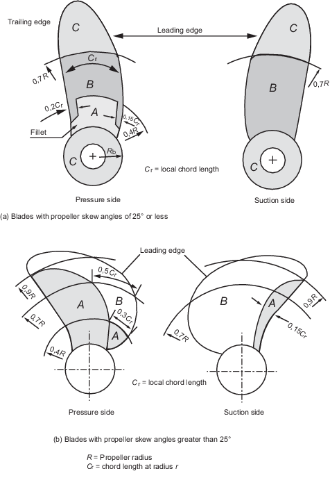
Figure 9.1.2 Severity zones in all propeller
blades
1.8.4
Skew angles of 25° or less:
- Zone A is the area on the pressure side of the blade from and including
the root fillet to 0,4R and bounded on either side by lines at a distance
0,15 times the chord length Cr from the leading edge and 0,2 times
Cr from the trailing edge, respectively. Where the hub radius
(Rb) exceeds 0,27R, the other boundary of zone A is to be
increased to 1,5Rb.
- Zone B includes the areas inside 0,7R on both sides of the
blade, excluding Zone A.
- Zone C includes the areas outside 0,7R on both sides of the
blade.
1.8.5
Skew angles of greater than 25°:
- Zone A is the area on the pressure side of the blade bounded by, and
including, the root fillet and a line running from the junction of the leading edge
with the root fillet to the trailing edge at 0,9R and passing through the
mid-point of the chord at 0,7R and a point situated at 0,3 of the chord length
from the leading edge at 0,4R.
- Zone A also includes the area along the trailing edge on the suction
side of the blade from the root to 0,9R and with its inner boundary at 0,15 of
the chord length tapering to meet the trailing edge at 0,9R.
- Zone B constitutes the whole of the remainder of the blade
surfaces.
1.8.6 In propeller blades with continuously loaded tips (CLT), the whole of the
tip plate and the adjoining blade to a distance of 100 mm is to be regarded as severity
Zone B, see
Figure 9.1.3 Severity Zone B at continuously
loaded blade tip. For propellers with diameters less than 2 m, the
width of this zone may be reduced to one tenth of the propeller radius.
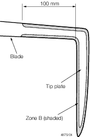
Figure 9.1.3 Severity Zone B at continuously
loaded blade tip
1.8.8 If a CPP blade has an integrally cast journal, the fillets of the journal
and the adjoining material up to a distance of 20 mm from the fillet run-outs are to be
regarded as Zone B, as indicated in Figure 9.1.5 Severity zones in integrally cast
CPP blade journals. The remainder of the surface of the journal may be
regarded as Zone C.
1.8.10 On completion of machining and grinding, the whole surface of each casting is
to be subjected to a liquid penetrant inspection in accordance with a procedure
acceptable to LR.
1.8.12 Liquid penetrant inspections on Zones B and C are to be performed by the
manufacturer and may be witnessed at the Surveyor’s request.
1.8.15 All defects requiring repair by welding in new propeller castings are to be
recorded on sketches showing their locations and dimensions. Copies of these sketches
are to be presented to the Surveyor prior to repair.
1.8.16 Where repairs have been made either by grinding, straightening or welding,
the repaired areas are to be subjected to dye liquid penetrant inspection in the
presence of the Surveyor, regardless of their location and/or severity zone.
1.8.17 Where no welds have to be made on a casting, the manufacturer is to provide
the Surveyor with a statement that this is the case.
1.8.18 Where it is suspected that a casting contains internal defects, or where
deemed necessary by the manufacturer or Surveyor, further volumetric NDE should be
carried out, where practical, in the form of radiographic and/or ultrasonic testing. The
acceptance criteria are to be agreed between the manufacturer and LR in accordance with
a recognised standard. ASTM E272 (Severity Level 2) or equivalent is to be the
radiographic acceptance standard for copper alloy castings.
1.8.19 Due to the attenuating effect of ultrasound within cast copper alloys, ultrasonic
testing may not be effective in some cases, depending on the shape/type/thickness, and
grain growth direction of the casting. Generally, ultrasonic testing of Cu 1 and Cu 2
grades is not effective. For Cu 3 and Cu 4, ultrasonic inspection of defects may be
possible and effective ultrasound penetration into the casting is to be practically
demonstrated on the item. This would normally be determined by way of back-wall
reflection, and/or target features within the casting. In the absence of any proposed
acceptance standard by the manufacturer, UT acceptance criteria is to comply with the
requirements of Ch 4, 4.6 Non-destructive examination 4.6.2.
1.8.20 Advanced NDE methods, as described in Ch 1, 5.11 Advanced NDE methods, may be applied to
Cu 3 and Cu 4 copper alloy castings for propellers, as appropriate to the material type,
thickness, complexity and geometry, as a substitute for, or complementary to
conventional ultrasonic or radiographic testing.
1.8.21 The measurement of dimensional accuracy is the responsibility of the
manufacturer but the report on dimensional inspection is to be presented to the Surveyor
who may require checks to be made and to witness such checks.
1.8.22 Static balancing is to be carried out on all propellers in accordance with
the approved plan. Dynamic balancing is necessary for propellers running above 500
rpm.
1.9 Rectification of defective castings
1.9.2 Where, in
the surface of the end face or bore of a propeller boss, local pores
are present which do not themselves adversely affect the strength
of the casting, they may be filled with a suitable plastic filler
after the appropriate preparation of the defective area. The foundry
is to maintain records and details of all castings which have been
so rectified.
1.9.3 Where unacceptable defects are found in a casting, they are to be removed
by mechanical means, and the surfaces of the resulting depressions are subsequently to
be ground smooth. Complete elimination of the defects is to be proved by adequate liquid
penetrant inspection.
1.9.4 Shallow grooves
or depressions resulting from the removal of defects may, at the discretion
of the Surveyor, be accepted provided that they will cause no appreciable
reduction in the strength of the castings and that they are suitably
blended by grinding.
1.9.5 Welded repairs
are to be undertaken only when they are considered to be necessary
and approved by the Surveyor. In general, welds having an area less
than 5 cm2 are to be avoided.
1.9.6 All weld
repairs are to be carried out in accordance with qualified procedures
by suitably qualified welders, and are to be completed to the satisfaction
of the Surveyor. Records are to be made available to the Surveyor.
1.9.7 Welding is
generally not permitted in Zone A and will only be allowed after special
consideration.
1.9.8 Prior approval
by the Surveyor is required for any welds in Zone B. Complete details
of the repair procedure are to be submitted for each case.
1.9.11 Where it is proposed to exceed the areas given in Table 9.1.3 Permissible rectification of new
propellers by welding, the nature and extent of the repair work are to be
approved by the Surveyor before commencement of the repair.
Table 9.1.3 Permissible rectification of new
propellers by welding
| Severity zone or region
|
Maximum
individual area of repair
|
Maximum total area of repairs
|
| Zone A
|
Weld repairs not generally permitted
|
| Zone B
|
Defects that are not deeper than (t/40) mm or 2
mm, whichever is greater, below the minimum local thickness are to be
removed by grinding. Defects which are deeper than allowable for removal by
grinding may be repaired by welding.
|
| Zone C
|
60
cm2 or 0,6% x S whichever is the greater
|
200
cm2 or 2% x S, whichever is the greater in combined
Zones B and C but not more than 100 cm2 or 0,8% x S,
whichever is the greater, in Zone B on the pressure side
|
| Other regions (see Note)
|
17
cm2 or 1,5% area of the region whichever is the greater
|
50
cm2 or 5% × area of the region whichever is the greater
|
| where
|
t = minimum local thickness in mm
|
|
|
S = area of one side of a blade = 0,79
|
|
|
D = finished diameter of propeller
|
|
|
B = developed area ratio
|
|
|
N = number of blades
|
Note Other regions include:
(a) the bore;
(b) the forward and aft faces of the boss;
(c) the outer surface of the boss to the start of the
blade root fillets;
(d) the inner face of a CPP blade palm;
(e) all surfaces of CPP nose cones;
(f) the surfaces of integral journals to CPP blades other
than the fillets.
|
1.9.12 The following definitions apply in relation to the assessment of indications when using
the liquid penetrant testing method:
- An indication is defined as the presence of detectable
bleed-out of the penetrant liquid from the material discontinuities appearing at
least 10 minutes after the developer has been applied (see Note 1).
- Relevant indication: Only indications which have any
dimension greater than 1,5 mm shall be considered relevant for the categorisation
of indications.
- Non-linear indication: an indication with a largest dimension
less than three times its smallest dimension (i.e. l < 3 w).
- Linear indication: an indication with a largest dimension
three or more times its smallest dimension (i.e. l ≥ 3 w).
- Aligned indications:
- Non-linear indications form an alignment when the
distance between indications is less than 2 mm and at least three
indications are aligned. An alignment of indications is considered to be a
unique indication and its length is equal to the overall length of the
alignment.
- Linear indications form an alignment when the distance
between two indications is smaller than the length of the longest
indication.
1: Where there is uncertainty
regarding the dimensions of the bleed-out indication size, either due to a large number
of small, grouped indications, or an indication experiences excessive bleed-out, the
penetrant testing process shall be repeated by strictly following the procedure.
Note In
exceptional circumstances, whereby the indication size cannot be accurately
determined, the actual discontinuity size may be further examined using visual
inspection methods, and augmented with the aid of magnification instruments, to
determine the actual size of the discontinuity, as visible on the surface of the
material.
1.9.13 Further examination is to be agreed with the Surveyor, and the Surveyor may, where
deemed necessary, request further NDE to ascertain the extent of indications, which may
include volumetric testing.
Table 9.1.4 Allowable number and size of
liquid penetrant indications in a reference area of 100 cm2
| Severity
Zones
|
Max. total number
of indications
|
Type of indications
(see Note 2)
|
Max. number of each
type (see Notes 3 and 4)
|
Max. acceptable
value for 'w’ or 'l' of indications (mm) (see Note 2)
|
| A
|
7
|
Non-linear
|
5
|
4
|
| Linear
|
2
|
3
|
| Aligned
|
2
|
3
|
| B
|
14
|
Non-linear
|
10
|
6
|
| Linear
|
4
|
6
|
| Aligned
|
4
|
6
|
| C
|
20
|
Non
linear
|
14
|
8
|
| Linear
|
6
|
6
|
| Aligned
|
6
|
6
|
Note
1. The reference area is defined as an
area of 0,01 m2, which may be square or rectangular,
with the major dimension not exceeding 250 mm. The area shall be
taken in the most unfavourable location relative to the indication
being evaluated.
Note
2. Non-linear, linear and aligned
indications are defined as follows:
|

|
Note
3. Single non-linear indications less
than 2 mm in Zone A and less than 3 mm in other zones are not
considered relevant.
Note
4. The total number of non-linear
indications may be increased to the maximum total number, or part
thereof, represented by the absence of linear or aligned
indications.
|
1.9.14 Areas which are prepared for welding are independent of their location and
are always to be assessed according to Zone A. The same applies to the welded areas
after being finished by machining and/or grinding.
1.10 Weld repair procedure
1.10.1 Welding is to be carried out under cover in positions free from draughts
and adverse weather conditions.
1.10.2 The manufacturer is to submit a detailed welding procedure specification
covering the weld preparation, welding parameters, filler metal, preheating, post-weld
heat treatment and inspection procedures.
1.10.3 Before welding is started, Welding Procedure Qualification tests are to be
carried out and witnessed by the Surveyor. Each welder is to be qualified in accordance
with the requirements of Ch 12, 5 Welder qualification tests.
1.10.4 The requirements of Ch 12, 4.2 Requirements for copper alloys are to be
followed for the welding procedure qualification with the following exceptions and
additions:
- The test assembly should consist of cast material and its
thickness should not be less than 30 mm.
- Bend test may be replaced with fracture test in accordance
with ISO 9017. Where fracture test is used, four fracture specimens are to be
tested, two extracted from the middle and two from the end of the test weld
length. The minimum length of each specimen is to be 20 mm and side notches are to
be used. Fracture test results are to be assessed in accordance with the
acceptance criteria specified for the Non-Destructive Examination in Ch 12, 2.5 Non-destructive examination (NDE) 2.5.5.
- The qualification range for base material thickness is given
in Table 9.1.5 Thickness approval range.
- Approval for a test made in any welding position is
restricted to that welding position.
- The approval is only valid for the welding consumable trade
name used in the welding procedure test.
Table 9.1.5 Thickness approval range
| Test assembly thickness, t (mm)
|
Thickness range approved
|
| t ≥ 30 mm
|
≥ 3 mm
|
1.10.5 Defects to be repaired by welding are to be removed completely by mechanical
means (e.g. grinding, chipping or milling). Removal of defects in accordance with the
requirements for Zone A is to be demonstrated by liquid penetrant inspection in the
presence of the Surveyor. The excavation is to be prepared in a manner which will allow
good fusion and is to be clean and dry.
1.10.6 Metal arc welding with the electrodes or filler wire used in the procedure
tests is to be used for all types of repairs. Welds should preferably be made in the
downhand (flat) position. Suitable preheat is to be applied before welding, and the
preheat temperature is to be maintained until welding is completed.
1.10.7 When flux coated electrodes are used they are to be dried immediately
before use, in accordance with the manufacturer's instructions.
1.10.8 All slag, undercuts and other defects are to be removed before the
subsequent run is deposited.
1.10.9 With the exception given in Ch 9, 1.10 Weld repair procedure 1.10.10, all weld repairs in areas of solid propellers
exposed to sea-water, and all repairs to separately cast blades, are to be stress relief
heat treated.
1.10.10 Stress relief heat treatment is not mandatory after welding Grade Cu 3
castings in Zone C unless a welding consumable susceptible to stress corrosion (e.g.
complying with the composition range of Grade Cu 4) is used. All welds in Zones A and B
however, must be stress relieved by heat treatment, regardless of alloy.
1.10.11 Propeller and propeller blades are to be stress relieved within the
following temperature ranges:
| alloy Grades Cu 1 and Cu 2
|
350°C to 550°C
|
| alloy Grade Cu 3
|
450°C to 500°C
|
| alloy Grade Cu 4
|
450°C to 600°C
|
Soaking times are to be in accordance with Table 9.1.6 Soaking times for stress relief
heat treatment of copper alloy propellers, and subsequent cooling from the soaking temperature
is to be suitably controlled to minimise residual stresses and is not to exceed 50°C per
hour until the temperature is below 200°C. Care should be taken to avoid heating
castings in the Grade Cu 3 alloy at temperatures between 300 and 400°C for prolonged
periods.
Table 9.1.6 Soaking times for stress relief
heat treatment of copper alloy propellers
| Stress relief
temperature °C (see Notes)
|
Alloy Grade Cu1 and Cu2
|
Alloy Grade Cu3 and Cu4
|
| Hours
per 25 mm of thickness
|
Maximum recommended total time hours
|
Hours
per 25 mm of thickness
|
Maximum
recommended total time hours
|
| 350
|
5
|
15
|
—
|
—
|
| 400
|
1
|
5
|
—
|
—
|
| 450
|
½
|
2
|
5
|
15
|
| 500
|
¼
|
1
|
1
|
5
|
| 550
|
¼
|
½
|
½
|
2
|
| 600
|
–
|
–
|
¼
|
1
|
Note
1. Treatment at 550°C is not applicable
to alloy Grade Cu3.
Note
2. Treatment at 600°C is only applicable
to alloy Grade Cu4.
|
1.10.12 Stress relief heat treatment is to be carried out, where possible, in
furnaces having suitable atmosphere and temperature control. Sufficient thermocouples
are to be attached to the casting to measure the temperature at positions of extremes of
thickness.
1.10.13 As an alternative to Ch 9, 1.10 Weld repair procedure 1.10.12, local stress relief heat treatment may be
accepted, provided that the Surveyor is satisfied that the technique will be effective
and that adequate precautions are taken to prevent the introduction of detrimental
temperature gradients. Where local stress relief heat treatment is approved, adequate
temperature control is to be provided. The area of the propeller or blade adjacent to
the repair is to be suitably monitored and insulated to ensure that the required
temperature is maintained and that temperature gradients are moderate. Care should be
taken to select the shape of an area to be heat treated which will minimise residual
stresses.
1.10.14 On completion, welds are to be ground smooth for visual examination and dye
penetrant inspection. Where a propeller or propeller blade is to be stress relief heat
treated, a visual examination is to be made before heat treatment, and both visual and
dye penetrant examinations are to be made after the stress relief heat treatment.
Irrespective of location, all weld repairs are to be assessed according to Zone A in
Table 9.1.4 Allowable number and size of
liquid penetrant indications in a reference area of 100 cm2
1.10.15 The foundry is to maintain full records detailing the weld procedure, heat
treatment and extent and location on drawings of repairs made to each casting. These
records are to be available for review by the Surveyor, and copies of individual records
are to be supplied to the Surveyor on request.
1.10.16 LR reserves the right to restrict the amount of repair work accepted from a
manufacturer when it appears that repetitive defects are the result of improper foundry
techniques or practices.
1.11 Straightening
1.11.1 The extent and procedure of straightening is to be agreed with the
Surveyor.
1.11.2 Static loading is to be used for hot and cold straightening of propeller.
1.11.3 Weld repaired areas may be subject to hot straightening, provided that it
can be demonstrated that weld properties are not impaired by the hot straightening
operations.
1.11.4 Hot straightening of a bent propeller blade or a pitch modification is to
be carried out after heating the bent region and approximately 500 mm wide zones on
either side of it to the temperature range given in Table 9.1.7 Hot straightening temperatures.
1.11.5 The heating for hot straightening is to be slow and uniform and the
concentrated flames such as oxyacetylene and oxypropane should not be used.
Sufficient time is to be allowed for the temperature to become uniform through the
full thickness of the blade section. The temperature is to be maintained within the
suggested range throughout the straightening operation. A thermocouple instrument or
temperature indicating crayons are to be used for measuring the temperature.
Table 9.1.7 Hot straightening temperatures
| Alloy Type
|
Hot straightening temperature °C
|
| CU1
|
500 - 800
|
| CU2
|
500 - 800
|
| CU3
|
700 - 900
|
| CU4
|
700 - 850
|
1.12 Identification
1.12.1 Castings
are to be clearly marked by the manufacturer in accordance with the
requirements of Ch 1 General Requirements. The following
details are to be shown on all castings which have been accepted:
-
Identification mark which will enable the full history of the item to
be traced including the manufacturer’s mark.
-
Alloy grade.
-
LR or Clasifications Register
and the abbreviated name of LR local office.
-
Personal stamp of
Surveyor responsible for the final inspection.
-
Date of final inspection.
-
Skew angle if in excess of 25°. See
Pt 5, Ch 7, 1 Plans and particulars of the Rules and Regulations for the Classification of Ships, July 2022 for
the definition of skew angle.
-
The number of the test certificate.
-
Ice class symbol, where applicable.
1.13 Certification of materials
1.13.2 The manufacturer
is to provide the Surveyor with the following particulars for each
casting:
-
Purchaser's name and order number.
-
Description of casting, to include diameter, number of blades, pitch,
direction of turning, and drawing number.
-
Alloy designation and/or trade name, and chemical composition of each
heat.
-
Heat or casting number.
-
Cast identification number if different from (d).
-
Details of heat treatment, where applicable.
-
Skew angle if in excess of 25°. See the relevant Rules for the
definition of skew angle.
-
Final weight of casting.
-
Results of non-destructive tests and details of test procedures.
-
Proportion of alpha-structure for CU1 and CU2 alloys.
-
Results of mechanical tests.
-
A sketch showing the location and extent of welding repairs (if
any).
- Shipbuilding project number, if known.
|