
Section
1 Introduction
1.1 General
1.1.1 This
Chapter contains information regarding the derivation of local design
loads that are to be used for the assessment of scantlings to local
loads as specified in Vol 1, Pt 6, Ch 2 Design Tools
1.1.2 The
formulae for ship motion loads given in this Chapter are suitable
for all ships that operate in the displacement mode. Ship motion loads
for ships that operate in the fully planing mode will need to be specially
considered.
1.2 Environmental conditions
1.2.1 The
environmental conditions for the determination of the local loads
are to be based on the normal environmental design criteria specified
in Vol 1, Pt 5, Ch 2, 2.3 Wave environment unless otherwise
stated.
1.2.2 The
wave height factor for local loads, f
Hs, is
dependent on the service area notation and is to be taken as follows:
|
f
Hs
|
= |
1,0 for SA1 service area notation, i.e. unrestricted sea-going
service |
otherwise
|
f
Hs
|
= |

|
| = |

|
f
Hs is not to be taken as less than
0,5
H
dw is given in Vol 1, Pt 5, Ch 2, 2.3 Wave environment 2.3.3.
1.2.4 The
local design loads for assessment of the residual strength notation, RSA, or for special loading conditions where the ship will
not experience severe weather or severe sea states may be adjusted
for the appropriate environmental conditions. A reduced wave height
factor, f
Hs, may be applied, see
Vol 1, Pt 5, Ch 3, 5.10 Design loads for RSA notation assessmentand Vol 1, Pt 5, Ch 3, 5.10 Design loads for RSA notation assessment 5.10.3.
1.3 Symbols and definitions
1.3.1 The symbols and definitions applicable to this Chapter are defined below or
in the appropriate sub-Section. LWL, B, BWL,
D, T and Cb are defined in Vol 1, Pt 3, Ch 1, 5.2 Principal particulars.
|
V
cr
|
= |
two thirds the cruising speed, in knots |
|
V
sp
|
= |
is to
be taken as the greater of the cruising speed or two thirds the sprint
speed, in knots. For ships where it is not required to maintain high
speeds in severe weather then the value of V
sp may
be specially considered
|
|
T
|
= |
mean draught at midships, in metres, to the design draught waterline
measured from the moulded baseline |
|
Tx
|
= |
local draught, in metres, measured from the underside of the keel to
the design draught waterline at the longitudinal position under consideration,
see
Figure 3.1.2 Definition of symbols. For the calculation of bottom impact
pressures, Tx (TFB) is to be taken as the
minimal draught for all operational loading conditions measured from the underside
of the keel to the operational waterline at the longitudinal position under
consideration, see
Vol 1, Pt 5, Ch 3, 4.2 Bottom impact pressure, IPbi 4.2.1. |
|
xwl
|
= |
longitudinal distance, in metres, measured forwards from the
aft end of the L
WL to the position or centre
of gravity of the item being considered
|
|
y
|
= |
transverse
distance, in metres, from the centreline to the centre of gravity
of the item being considered. y is positive to port and
negative to starboard
|
|
z
|
= |
vertical
distance, in metres, from the base line to the position or centre
of gravity of the item being considered. z is positive
above the baseline
Normally the following definitions
are to be applied:
For a longitudinally framed plate
panel, z is to be taken at the panel centre
For
a transversely framed plate panel, z is to be taken at
two thirds of the panel height
For short stiffener members: z is to be taken at the stiffener mid position
For
long stiffener members: z is generally to be taken at
the stiffener mid position, but may need to be specially considered,
especially when there is a significant pressure variation along its
length
|
|
∆ |
= |
moulded
displacement of the ship, in tonnes |
1.3.2
Froude
Number F
n.
The Froude number is a nondimensional
parameter which is the primary constituent part of the wave making
resistance and which dictates the maximum displacement speed. It is
defined as:
|
F
n
|
= |

|
where
|
g
|
= |
is the acceleration
due to gravity and is taken to be 9,81 m/s2
|
|
V
m
|
= |
is the
appropriate ship speed in m/s. |
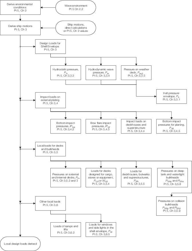
Figure 3.1.1 Overview of derivation of local design loads
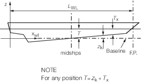
Figure 3.1.2 Definition of symbols
1.3.3
Design loading condition. The design loading condition is to be taken as the
draught condition with tanks and consumables, etc. in the departure state, see
also
Vol 1, Pt 5, Ch 4, 2.1 General 2.1.3. Where there is a significant
variation in loading conditions or operating modes, then it may be necessary to consider
additional loading conditions which represent the extremes of service requirements. For
example:
- a ship which can operate in displacement and non-displacement
modes;
- a ship which is required to operate at a temporary draught deeper than
the design draught for off-loading payload.
- a ship which is required to be involved in humanitarian emergency
evacuation incidents or similar situations where short term overloading
may be necessary.
1.3.4
LCG. The
LCG is the longitudinal centre of gravity of the ship measured in
metres from the aft end of the L
WL for the
design loading condition.
1.3.5
Displacement
mode. Displacement mode means the regime, whether at rest or
in motion, where the weight of the ship is fully or predominantly
supported by hydrostatic forces. Typically this applies to craft with
a Taylor Quotient, Γ, less than 3. However, some craft are designed
to plane with Γ less than 3 and these should be considered as
operating in the non-displacement mode.
1.3.6
Fully
planing mode or Non-displacement mode. Non-displacement mode
means the normal operational regime of a ship when non-hydrostatic
forces substantially or predominantly support the weight of the ship.
Typically this applies to craft with a Taylor Quotient, Γ, greater
than 3. However, some craft are designed not to plane with Γ greater
than 3 and these should be considered as operating in the displacement
mode unless they are classified as a high speed craft.
1.3.7 Taylor
Quotient Γ. The Taylor Quotient is defined as:
1.3.8
Support
girth G
S
. The support girth is the
girth distance at the LCG, in metres, and is to be calculated as follows:
- For craft with chines, it is to be taken as the distance around
the shell plate between the girth chine locations, see
Figure 3.1.3 Definition of girth chine location, B
C, B
WL and G
S when chine is
below deepest load waterline
. Girth chine location
is to be taken as the lowest chine above which the shell plate has
an angle to the horizontal greater than 50°.
- For craft where the design waterline intercepts the shell plate
below the bilge tangential point or the girth chine location, the
support girth is to be taken as the distance around the shell plate
up to the design waterline, see Fig. Figure 3.1.4 Definition of girth chine location, B
C, B
WL and G
S when chine is
above deepest load waterline
.
- For craft with round bilges, it is to be taken as the distance
around the shell plate between the bilge tangential points of the
hull. The bilge tangential point is defined as the tangential point
of the bilge with an oblique line sloped at 50° to the horizontal
at the LCG, see
Figure 3.1.5 Definition of bilge tangential point, B
C, B
WL and G
S
.
- For multi-hull craft, it is to be taken as the summation of girths
for each individual hull between the inner and outer bilge tangential
points or chines, as appropriate.
The definition aims to define the canoe body. Narrow keels and
skegs can be ignored.
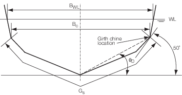
Figure 3.1.3 Definition of girth chine location, B
C, B
WL and G
S when chine is
below deepest load waterline
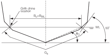
Figure 3.1.4 Definition of girth chine location, B
C, B
WL and G
S when chine is
above deepest load waterline

Figure 3.1.5 Definition of bilge tangential point, B
C, B
WL and G
S
|