
Section
5 Local design loads for decks and bulkheads
5.1 General
5.1.1 This
section gives formulations for design pressure loads for decks, watertight
and deep tank boundaries including decks and bulkheads.
5.1.2 The
loads acting on the deck structures are to reflect the intended purpose
for each deck. If it is envisaged that the role of the ship will be
such that it may be used for emergency evacuation incidents or similar
situations, then the appropriate design loads are to be considered
in the assessment. The maximum permissible deck loading are to be
recorded in the Operations Manual or Stability Information Book.
5.2 Pressure on external decks
5.2.1 The
standard pressure requirements for external decks are given in Vol 1, Pt 5, Ch 3, 3.5 Pressure on exposed and weather decks, Pwd. If the deck is also to be used
for cargo, heavy equipment or similar, then the loads specified in Vol 1, Pt 5, Ch 3, 5.4 Loads for decks designed for cargo or heavy equipment loads, Pcd and Wcd are also to be applied. Consideration
will be given to a reduction in the weather deck pressure loading
if it can be shown that the cargo or equipment stowage makes the weather
deck pressure requirements conservative.
5.3 Pressure on internal decks, P
in
5.3.1 The
pressure acting on internal decks, P
in, not
subject to cargo or heavy equipment loads is to be taken as:
|
P
in
|
= |
5 kN/m2 for accommodation spaces
|
|
P
in
|
= |
7,5 kN/m2 for main evacuation routes
|
|
P
in
|
= |
10 kN/m2 for workshop spaces
|
|
P
in
|
= |
20 kN/m2 for store spaces.
|
5.3.2 Alternatively
the design pressure is to be based on the static loading on the deck
with due allowance for inertial effects as follows:
|
P
in
|
= |
W
in ( 1 + a
z )
kN/m2
|
where the following values of static pressure are
to be assumed
|
W
in
|
= |
3 kN/m2 for accommodation spaces
|
|
W
in
|
= |
6 kN/m2 for workshop spaces
|
|
W
in
|
= |
12 kN/m2 for store spaces
|
a
z is defined in Vol 1, Pt 5, Ch 3, 2.3 Design accelerations 2.3.2.
5.3.3 The
hydrostatic design pressure for decks specified as watertight shall
be taken as that determined by the damage stability analysis and limit
of watertight integrity.
5.3.4 The
static design pressure for internal decks not specified as watertight
may be provided by the designer.
5.4 Loads for decks designed for cargo or heavy equipment loads, P
cd and W
cd
5.4.1 Where
the load applied to the deck can be considered as uniformly distributed,
the cargo deck design pressure, P
cd, is to
be taken as:
|
P
cd
|
= |
W
cd (1 + az) kN/m2
|
5.4.2 Where
the load applied to the deck is not uniformly distributed, the likely
actual forces and force distribution over the deck must be considered.
The forces are to include the following if appropriate:
- gravity
- inertial forces due to ship motion.
- wind loads
- forces imposed by the securing arrangements
- wave impact loads
- icing loads
where
W
ma is
the weight of each mass item on the deck as specified by the designer
in kN
5.5 Loads for deckhouses, bulwarks and superstructures, P
dh
5.5.1 The
design normal pressure, P
dh, for the side,
front and back panels of plating and stiffeners for deckhouses, bulwarks
and superstructures is given by:
where
|
C
1
|
= |
1,25C
2 for exposed deckhouse fronts
and superstructure fronts forward of 0,67L
R
|
| = |
1,15C
2 for exposed
deckhouse fronts and superstructure fronts aft of 0,67L
R
|
| = |
1,15 for exposed machinery casings |
| = |
0,8 for the side and back panels of deckhouses
that are stepped in from the deck edge by 1,0 m or more which are
also above the nominal wave limit height, H
w, see
Vol 1, Pt 5, Ch 3, 3.4 Hydrodynamic wave pressure, Pw 3.4.4
|
| = |
0,5 for non-exposed deckhouse and super structure
fronts, sides and backs which are also above the nominal wave limit
height |
| = |
1,0 elsewhere |
|
P
s
|
= |
is to
be taken at the height of the deck supporting the deckhouse front,
side or back panel under consideration, P
s is
defined in Vol 1, Pt 5, Ch 3, 3.2 Combined hydrostatic and hydrodynamic pressure on the shell plating, Ps
|
|
C
2
|
= |
1,2 for panels below the nominal wave limit height |
| = |
1,0 elsewhere |
|
|
= |
Typical values of C
1 are shown in Figure 3.5.1 Illustration of the C1 coefficients for deckhouse
and superstructure pressures
|
|
|
= |
Where there is more than one deckhouse, the front of the most
forward deckhouse will normally be considered exposed, whereas the
back of this deckhouse will be non-exposed. Normally, the front of
the deckhouse aft of this one will also be considered non-exposed. |

Figure 3.5.1 Illustration of the C1 coefficients for deckhouse
and superstructure pressures
5.6 Pressure height for deep tank bulkheads and boundaries, H
tk
5.6.1 The
design lateral pressure height for tank and deep tank bulkheads and
boundaries, H
tk, is to be taken as
|
H
tk
|
= |
the distance, in m, from the baseline to half the distance from
the top of the tank to the top of the overflow. For determination
of the maximum head, the top of the overflow is to be taken as not
less than 1,8 m above the crown of the tank, see
Figure 3.5.2 Pressure height for deep tank bulkheads
|
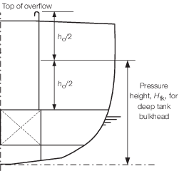
Figure 3.5.2 Pressure height for deep tank bulkheads
5.6.2 For
tanks which are connected to a filling tank system, H
tk may be taken as the distance, in m, from the baseline to the
highest point of the overflow pipe from the filling tank into the
overflow tank. Consideration may need to be given to the pressure
height for situations where any of the valves in the filling system
may be closed. The transfer pump must feed only into the filling tank
and must not be linked directly to the tanks.
5.6.3 In a
filling tank system, suitable measures are to be provided such that
the maximum design level in the system cannot be exceeded. Automatic
shutdown measures are to ensure a fail safe arrangement to avoid overfilling
the filling tank or the overflow tank. The overflow pipe is to be
of sufficient size to ensure that the filling trunk is not overfilled.
5.7 Pressure height for watertight bulkheads
and boundaries, Hda
5.7.1 The design lateral pressure height for watertight bulkheads and boundaries,
Hda, is to be taken as
-
for a watertight bulkhead design philosophy based on a SOLAS type
approach, i.e. to the top of a watertight bulkhead deck or freeboard deck,
see
Vol 1, Pt 3, Ch 2, 1.3 Watertight and weathertight integrity 1.3.8 and illustrated in Figure 2.1.1 .
Hda =
the vertical distance, in m, from baseline to a line 0,91 m above the top of the
watertight bulkhead at side, see
Figure 3.5.3 Pressure height for watertight bulkheads.
-
for a watertight bulkhead design philosophy based on a standard which
requires a damaged stability draught and heel envelope approach, e.g. the red risk
line approach, see
Vol 1, Pt 3, Ch 2, 1.3 Watertight and weathertight integrity 1.3.9 and illustrated in Figure 2.1.2 .
Hda
= the distance, in m, from baseline to the damaged stability draught envelope at
the centreline, see
Figure 3.5.3 Pressure height for watertight bulkheads.
Note: The effect of lesser angles of heel in the damage situation may lead
to an increase in the effective pressure height, especially in way of the forward end of
the ship where it may be necessary to consider Hda based on a zero
heel angle.
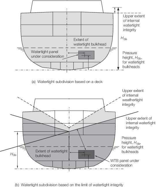
Figure 3.5.3 Pressure height for watertight bulkheads
5.8 Design pressures for watertight and deep tank bulkheads and boundaries
5.8.1 The
design normal pressure for bulkhead plating with stiffeners is to
be considered separately for the plating and the stiffeners. The design
normal pressure for the plating, P
bhp, is
to be taken as follows:
Deep Tank
ρg (H
tk – z
p) kN/m2
WT sub-division
based on the head normal to the line of watertight integrity
maximum of
10((H
da – z
p) cosθ +y
p sin
θ) kN/m2
10(H
da – z
p) kN/m2
where
|
ρ
|
= |
density
of fluid, in tonnes/m3, and is not to be taken as less
than 1,025
|
|
z
p
|
= |
distance above the baseline of a point one-third of the height,
above the lower edge, of the plate strake under consideration, z
p is illustrated in Figure 3.5.4
Z, distance above baseline for pressure head
for plating with horizontal stiffeners
for
horizontally stiffened plating and Figure 3.5.5
Z, distance above baseline for pressure head
for plating head for plating with vertical stiffeners
for vertically stiffened plating
|
|
y
p
|
= |
distance from the centreline of the mid-breadth of the plate
strake under consideration, y
p, is always
to be taken as positive
|
|
θ |
= |
the stipulated
damaged stability heel angle, see also
Vol 1, Pt 3, Ch 2, 1.3 Watertight and weathertight integrity For a SOLAS type approach, θ
is normally to be taken as 0,0.
|
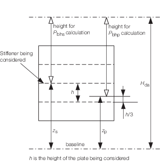
Figure 3.5.4
Z, distance above baseline for pressure head
for plating with horizontal stiffeners
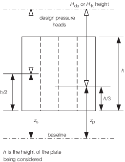
Figure 3.5.5
Z, distance above baseline for pressure head
for plating head for plating with vertical stiffeners
5.8.2 The
design normal pressure for the stiffener, P
bhs,
is to be taken as follows:
Deep Tank
ρg (H
tk - z
s) kN/m2 (Deep Tank)
WT sub-division
maximum of:
10((H
da - z
s) cos θ + y
s sin θ)
kN/m2
10(H
da - z
s) kN/m2
where
or
|
y
s
|
= |
distance from the centreline of the mid span of the stiffener
under consideration, y
s is always to be taken
as positive
|
|
ρ
|
= |
density
of fluid, in tonnes/m3, and is not to be taken as less
than 1,025.
|
5.8.3 The
appropriate design criteria are to be applied to the bulkhead plating
and stiffeners, see
Vol 1, Pt 6, Ch 5 Structural Design Factors It is not permissible to use watertight criteria for
a deep tank design head.
5.8.4 The
design impulse pressure,  bh, for the bulkhead plating and stiffeners
may be ignored, unless these members are likely to be subjected to
significant sloshing loads or similar. In this case it will be necessary
to determine the sloshing loads using a suitable direct calculation
procedure.
bh, for the bulkhead plating and stiffeners
may be ignored, unless these members are likely to be subjected to
significant sloshing loads or similar. In this case it will be necessary
to determine the sloshing loads using a suitable direct calculation
procedure.
5.9 Design pressures for collision bulkheads
5.9.1 The
design lateral pressure height for collision bulkheads, H
cb, is to be taken as:
|
H
cb
|
= |
the vertical distance, in m, from the baseline to 0,91 m above
the uppermost point of the collision bulkhead. |
5.9.2 The
design normal pressure for the collision bulkhead plating, P
bhp, is to be taken as:
|
P
bhp
|
= |
10 (H
cb – z
p)
kN/m2
|
where
|
z
p
|
= |
distance above baseline of a point one third of the height,
above the lower edge, of the plate strake under consideration. |
5.9.3 The
design normal pressure for bulkhead stiffeners, P
bhs,
is to be taken as:
|
P
bhs
|
= |
10 (H
cb – z
s)
kN/m2
|
5.9.5 If there
is a design requirement for the ship to be able to remain operational
after an incident which results in the collision bulkhead becoming
the primary watertight boundary to the sea, then it will be necessary
to design the collision bulkhead using the pressures for the shell
envelope, P
s, given in Vol 1, Pt 5, Ch 3, 3 Loads on shell envelope and the shell envelope design
criteria. It will also be necessary to consider the effects of wave
impact pressures, see
Vol 1, Pt 5, Ch 3, 4.3 Bow flare and wave impact pressures, IPbf,
using the design speed requirement after damage.
5.10 Design loads for RSA notation assessment
5.10.1 The
capability of transverse bulkheads, longitudinal bulkheads, watertight
decks and other structure to withstand any additional loads as a consequence
of damage, e.g. sloshing loads on watertight bulkheads, may need to
be specially considered. Pressure heads consistent with draughts and
heel angles determined from the damage stability analyses are to be
used for local scantling assessment.
5.10.2 Where
watertight boundaries for damage control purposes are specified in
the subdivision and stability standard, the nominated bounding decks
are to be assigned as watertight see
Vol 1, Pt 6, Ch 3, 10 Deck structures. The pressure heads used
in the assessment of damage control decks are to be the greater of
that determined from the Rules or that specified by the Owner.
5.10.3 The local design loads for structures subjected to additional loading as a
consequence of structural damage are to be taken as specified in this Chapter except
that the wave height factor, fHs, may be reduced, to account for the
lesser environmental requirements, as follows:
|
fHs
|
= |
may be
reduced by a factor of 1,85 |
5.10.4 Where
local strength issues need to be considered, the following local loads
are to be applied in the evaluation contained in Vol 1, Pt 6, Ch 4, 4.1 Application:
- Hydrostatic load due to flooding, taking account of the increase in
local draught.
- Wave and inertial loads in the damaged condition, derived using
the reduction factor given in Vol 1, Pt 5, Ch 3, 5.10 Design loads for RSA notation assessment 5.10.3.
- Local loads on watertight divisions as a consequence of flooding. For
the evaluation of local loads on watertight divisions, the standard design pressure,
Hda (see
Vol 1, Pt 5, Ch 3, 5.7 Pressure height for watertight bulkheads and boundaries, Hda)
may be applied. Alternatively the external hydrostatic and wave pressure load,
Ps, may be applied using the reduction factor given in Vol 1, Pt 5, Ch 3, 5.10 Design loads for RSA notation assessment 5.10.3.
- Wave impact loads need not be considered unless a significant
operational requirement is necessary following damage.
5.11 Design pressure for magazine decks and bulkheads
5.11.1 For
magazine structure which is assessed in accordance with Pt 4, Ch 1,6.4
the quasi-static design pressure is to be taken as follows:
|
P
mag
|
= |

|
where
|
W
e
|
= |
weapon equivalent weight of TNT, in kg |
|
V
|
= |
free
compartment volume, in m3.
|
|