
Section
4 Impact loads on external plating
4.1 General
4.1.1 The
effects of impact or slamming loads on the shell envelope are to be
considered. This section gives formulations for equivalent design
pressure loads. Alternatively the impact pressure loads may be derived
using suitable direct calculation methods.
4.1.2 The
methods below produce average instantaneous impact pressures which
need to be converted to equivalent static pressures by application
of a dynamic load factor, see
Vol 1, Pt 6, Ch 2, 5 Dynamic loading and Vol 1, Pt 6, Ch 3, 14 Strengthening for bottom slamming and Vol 1, Pt 6, Ch 3, 15 Strengthening for wave impact loads above waterline.
4.1.3 These
methods are based on the Ochi-Motter slamming approach and are equivalent
to the standard direct calculation procedure. The values of m
0, variance of the relative vertical motion, and m
1, variance of the relative vertical velocity, may be derived
using direct calculations. In this case the variances are to be based
on sea states as defined by the normal design assessment environmental
criteria, see
Vol 1, Pt 5, Ch 2, 2.3 Wave environment.
4.2 Bottom impact pressure, IP
bi
4.2.1 The
bottom impact pressure due to slamming,  bi, is to be derived using the method given
below. This method will produce impact pressures over the whole of
the underwater plating region:
bi, is to be derived using the method given
below. This method will produce impact pressures over the whole of
the underwater plating region:
|
IP
bi
|
= |
0,5k
sl
V
bs
2 kN/m2
|
where

|
= |
hull form shape coefficient |
| = |
 for βp ≥ 10 for βp ≥ 10
|
| = |
28 (1– tan(2βp)) for
βp < 10
|
|
β p
|
= |
deadrise angle,in degrees, see
Figure 3.4.1 Bow flare and bottom slamming angles
|
|
V
bs
|
= |
slamming velocity, in m/s, and is given by |
| = |

|
| = |
0 for  < 1 < 1
|
|
V
th
|
= |
threshold velocity for slamming, in m/s, to be taken as: |
| = |

|

|
= |
No. of slams in a 3 hour
period and is given by |
| = |

|

|
= |
probability of a slam
and is given by |
| = |
e–u
|
|
u |
= |

|

|
= |
distance of the centroid
of the area of plating or stiffener to the local design waterline |
| = |
z – (T
x + z
k)
|
|
m
1
|
= |
variance of the relative vertical velocity |
| = |
0,25 (ω
e
f
 H
r m)2
H
r m)2
|
|
m
0
|
= |
variance of the relative vertical motion |
| = |
0,25 (f
 H
r m)2
H
r m)2
|
|
ω
|
= |
effective
wave frequency based on 80 per cent ship length |
| = |

|
|
ω
e
|
= |
effective encounter wave frequency |
| = |

|
|
H
r m
|
= |
relative vertical motion based on V
sp, see
Table 3.2.1 Ship motions
|
f

|
= |
probability level correction
factor for relative vertical motion |
| = |
1,0 |
V
sp, z, z
k and T
x are defined in Vol 1, Pt 5, Ch 3, 1.3 Symbols and definitions
See
Figure 3.4.1 Bow flare and bottom slamming angles.
4.2.2 For
the purposes of deriving the dynamic load factor, the rise time of
the impact pressure may be taken as:
|
t
r
|
= |

|
It is assumed that the impact pressure may be represented
by a triangular pulse load.
4.3 Bow flare and wave impact pressures, IP
bf
4.3.1 This
Section is applicable to:
-
Bow flare region.
-
Sides and undersides
of sponsons.
-
Other parts of
the side shell plating close to and above the design waterline that
are expected to be subjected to wave impact pressures.
The bow flare wave impact pressure, wave impact pressure on
sponsons and other parts of the side shell plating above the design
waterline, IP
bf, in kN/m2, due
to relative motion is to be taken as:

|
= |
0,5 (k
bf
V
bf
2 + k
rv
H
rv
V
rv
2) kN/m2
|
where
|
k
bf
|
= |
hull form shape coefficient for wave impacts |
| = |
 for ψ ≥ 10 for ψ ≥ 10
|
| = |
28 (1 – tan(2 ψ)) for ψ <
10 |
|
V
bf
|
= |
wave impact
velocity, in m/s, and is given by |
| = |
 for N
bf ≥ 1 for N
bf ≥ 1 |
| = |
 for N
bf < 1 for N
bf < 1
|
|
V
thbf
|
= |
threshold velocity for wave impact, in m/s, to be taken as: |
| = |

|
|
N
bf
|
= |
No of wave impacts in a 3 hour period and is given by |
| = |

|
|
PR
bf
|
= |
probability of a wave impact and is given by e–u
|
|
u |
= |

|
|
k
rv
|
= |
hull form shape coefficient for impact due to forward speed |
| = |
 for α
p ≤ 80 for α
p ≤ 80
|
| = |
28 (1 – tan(2 (90 – α
p)))
for α
p > 80
|
|
H
rv
|
= |
relative wave heading coefficient |
| = |
1,0 for γ
p ≥
45
|
| = |
cos(45-γ
p) for γ
p < 45 and ≥ 0
|
| = |
0 for γ
p <
0
|
|
V
rv
|
= |
relative forward speed, in m/s |
| = |
0,515 V
sp sin(γp)
|
|
α
p
|
= |
buttock angle measured in the longitudinal plane, in degrees, see
Figure 3.4.1 Bow flare and bottom slamming angles
|
|
ψ |
= |
effective
deadrise angle in degrees.
For C
b >
0,6, ψ is to be taken as the maximum of αp and
βp, see
Figure 3.4.1 Bow flare and bottom slamming angles
For C
b ≤ 0,6,
ψ is to be taken as the maximum of αp and β
where
β = βp – 10°,
but is to be taken as not less than 0°
NOTE
The
10° deduction is to allow for the effects of roll motion on the
impact pressures.
|
|
γ
p
|
= |
waterline angle, measured in the horizontal plane, in degrees, see
Figure 3.4.1 Bow flare and bottom slamming angles
|
|
C
b
|
= |
Block coefficient as defined in Vol 1, Pt 3, Ch 1, 5 Definitions
|
|
|
= |
z
wl, m
1, m
0, are defined in 4.2 but are to be calculated using:
|
|
f
sl
|
= |
probability level correction factor for relative vertical motion |
| = |
1,0 for ships C
b ≤
0,6
|
| = |
1,2 for ships C
b >
0,6
|
Note Where only two angles are known and are measured in the
orthogonal planes, then the third angle may be obtained by the following
expression:
If the area of plating under consideration has a
waterline angle which is re-entrant or decreasing, e.g. in the stern
region, then the relative wave heading coefficient, H
rv, and the speed V
sp, used in the derivation
of H
r m, are to be taken as zero. V
sp is defined in Vol 1, Pt 5, Ch 3, 1.3 Symbols and definitions 1.3.1
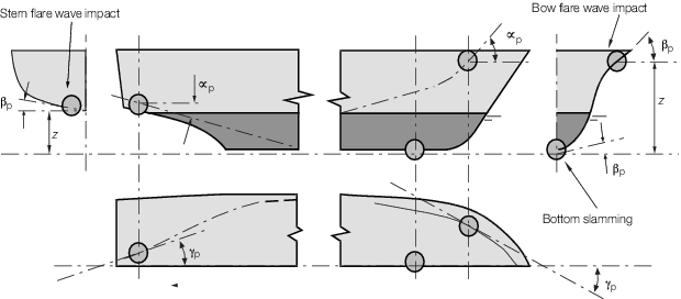
Figure 3.4.1 Bow flare and bottom slamming angles
4.3.2 For
the purposes of deriving the dynamic load factor, the rise time of
the wave impact pressure may be taken as:
|
t
r
|
= |

|
It is assumed that the wave impact pressure may be
represented by a triangular pulse load.
4.4 Impact loads on deckhouses and superstructures
4.5 Bottom impact pressure for ships operating in the planing regime
4.5.1 The
equivalent static bottom impact pressure due to slamming,  , at the LCG for planing hull forms is given by the following
expression: , at the LCG for planing hull forms is given by the following
expression:

|
= |

|
where
|
G
S
|
= |
support girth in metres, as defined in Vol 1, Pt 5, Ch 3, 1.3 Symbols and definitions 1.3.8
|
|
L
WL
|
= |
waterline length, in metres, see
Vol 1, Pt 5, Ch 3, 1.3 Symbols and definitions 1.3.1
|
|
a
op
|
= |
vertical acceleration as defined in Vol 1, Pt 5, Ch 3, 2.4 Design vertical acceleration for ships in the planing regime
|
|
k
dl
|
= |
hull form pressure factor |
| = |
54 |
|
|
= |
For craft in continuous contact with water: |

|
= |
0,5 for x = 0,0 L
WL
|
| = |
1,0 for x = 0,5 L
WL
|
| = |
1,0 for x = 0,75 L
WL
|
| = |
0,5 for x = 1,0 L
WL
|
Intermediate values to be determined by linear interpolation.
Otherwise = 1,0. = 1,0.
|