Section 
                     4 Design load systems for longitudinally effective components


                        4.1 Bottom shell structures (BS)


                              4.1.2 The
                                 design normal pressure, P
                                 BS, for the bottom
                                 shell plating and stiffeners is to be taken as:


                              where 


                              4.1.3 The
                                 design impulse pressure,  
                                 P
                                 BS, for the bottom shell plating
                                 and stiffeners is to be taken as


                                             P
                                             bi
                                              | 
                                       = | 
                                        kN/m2 (bottom
                                             impact)
                                              | 


                              where 


                              4.1.5 The
                                 design transverse load, LT
                                 BS, due to hydrostatic
                                 and hydrodynamic compressive loading is to be taken as follows:


                                       | 
                                                
                                             LT
                                             BS
                                              | 
                                       = | 
                                       –εBS 
                                             P
                                             SS 
                                             H
                                             d 
                                             S
                                             bs kN
                                              | 


                              where 


                                       | 
                                                
                                             H
                                             d
                                              | 
                                       = | 
                                       half the vertical distance from the keel to the first effective
                                             full breadth deck above the inner bottom, or above the keel, in m.
                                             If no effective full breadth decks exist, then H
                                             d is
                                             to be taken to the strength deck. H
                                             d is illustrated
                                             in Figure 2.4.2 Design parameter Hd for transverse
                                                load
                                                
                                              | 


                                       | 
                                                
                                             S
                                             bs
                                              | 
                                       = | 
                                       length of the bottom shell plating between major transverse
                                             bulkheads, in metres | 


                                       | 
                                                εBS
                                              | 
                                       = | 
                                       effectiveness
                                             of the bottom shell plating, i.e. the relative proportion of the load
                                             carried by the bottom shell as opposed to other structure such as
                                             the inner bottom, floors and bulkheads | 
                                        
                                          | = | 
                                          0,5 for full breadth double bottom structures | 
                                        
                                       
                                          | = | 
                                          1,0 for single bottom structures or partial
                                                breadth double bottom structures | 


                                 P
                                 SS is to be taken at a height H
                                 d/2 above the keel. P
                                 SS is
                                 defined in Vol  1, Pt  7, Ch  2,  3.6 External shell pressures 3.6.1


                              4.1.6 The
                                 design global shear force, Q
                                 D, may be ignored
                                 for the bottom plating.


                        4.2 Side shell structures (SS)


                              4.2.3 The
                                 design impulse pressure,  
                                 P
                                 SS, for the side shell plating
                                 and stiffeners is to be taken as follows:


                                 - 


up to the design
                                       waterline


                                       P
                                       SS =  
                                       P
                                       bi kN/m2 (bottom impact)


                                 - 


above the design
                                       waterline


                                       P
                                       SS =  
                                       P
                                       bf kN/m2 (bow flare
                                       impact)


                              where 


                                 P
                                 bi and  
                                 P
                                 bf are defined in Vol  1, Pt  7, Ch  2,  2.1 Nomenclature 2.1.2


                              4.2.5 The
                                 design vertical load, LV
                                 SS, supported by the
                                 side shell plating and stiffeners is to be taken as:


                                       | 
                                                
                                             LV
                                             SS
                                              | 
                                       = | 
                                       –εSS (S
                                             ss 
                                             B
                                             ss 
                                             P
                                             CD + L
                                             A +
                                             [F
                                             CD] ) kN
                                              | 


                              where 


                                       | 
                                                εSS
                                              | 
                                       = | 
                                       effectiveness
                                             of the side shell plating, i.e. the relative proportion of the load
                                             carried by the side shell as opposed to the bounding major transverse
                                             bulkheads | 
                                        
                                          | = | 
                                          0,5 | 


                                       | 
                                                
                                             L
                                             A
                                              | 
                                       = | 
                                       appropriate load, in kN, from pillar(s), bulkheads and side
                                             shell structure above the supported deck, assumed zero if there is
                                             none over. L
                                             A may be taken as LV
                                             BP for the supported bulkhead. LV
                                             PB is
                                             given in Vol  1, Pt  7, Ch  2,  5.8 Pillar bulkheads (PB)
                                              | 


                                       | 
                                                
                                             B
                                             ss
                                              | 
                                       = | 
                                       mean breadth of the supported deck plating, i.e. half the transverse
                                             distance from the side shell to longitudinal bulkheads, or effectively
                                             supported longitudinal girders, in metres | 


                                       | 
                                                
                                             S
                                             ss 
                                              | 
                                       = | 
                                       length of the side shell between major transverse bulkheads,
                                             in metres. | 


                        4.3 Strength deck and internal deck structures (DK)


                              4.3.1 The
                                 design normal pressure, P
                                 DK, for the deck
                                 plating and stiffeners is to be taken as the greater of the following,
                                 provided that the load component is applicable:


                                 - 


                                       P
                                       WD (weather
                                       deck pressure), see 
                                       Vol  1, Pt  7, Ch  2,  3.6 External shell pressures 3.6.2


                                 - 


                                         (interior deck pressure), see 
                                       Vol  1, Pt  7, Ch  2,  5.1 Deck structures (DK) 5.1.3


                                 - 


                                       P
                                       CD (cargo
                                       deck pressure), see 
                                       Vol  1, Pt  7, Ch  2,  5.1 Deck structures (DK) 5.1.2


                                 - 


                                       P
                                       tk (deep
                                       tank boundary, where appropriate).


                              4.3.3 The
                                 design load matrix, [F
                                 DK], in kN for the deck
                                 plating and stiffeners is to be taken as the combination of the following,
                                 as appropriate:


                              These loads are to be applied in addition to the
                                 design pressures above.


                              4.3.4 Normally,
                                 the design impulse pressure,  
                                 P
                                 DK, for the deck plating and stiffeners
                                 may be ignored. However, the design impulse pressure will need to
                                 be considered for decks designed to withstand helicopter or aircraft
                                 landing operations, cargo handling at sea or similar.


                              4.3.6 The
                                 design transverse load, LT
                                 DK, due to hydrostatic
                                 and hydrodynamic compressive loading is to be taken as follows, see
                                    also 
                                 Vol  1, Pt  7, Ch  2,  4.3 Strength deck and internal deck structures (DK) 4.3.8:


                                       | 
                                                
                                             LT
                                             DK


                                              | 
                                       = | 
                                       –εDK 
                                             P
                                             SS 
                                             H
                                             d 
                                             S
                                             dk kN
                                              | 


                              where 


                                       | 
                                                
                                             H
                                             d
                                              | 
                                       = | 
                                       half the vertical distance from the first full breadth deck
                                             below the deck under consideration to the first full breadth deck
                                             above this deck, or to the strength deck if there are no decks above,
                                             in metres | 


                                       | 
                                                εDK
                                              | 
                                       = | 
                                       effectiveness
                                             of the deck, i.e. the relative proportion of the load carried by the
                                             deck as opposed to other structure such as bulkheads | 
                                        
                                          | = | 
                                          0,8 | 


                                 P
                                 SS is to be taken at the
                                 mid height of the H
                                 d depth, P
                                 SS is defined in Vol  1, Pt  7, Ch  2,  3.6 External shell pressures 3.6.1


                                 H
                                 d is illustrated in Figure 2.4.2 Design parameter Hd for transverse
                                    load
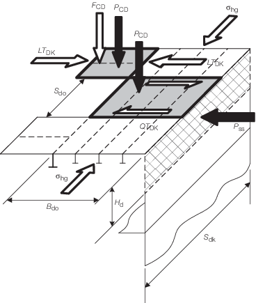


                                 Figure 2.4.4 Design loads for the deck structure


                              4.3.8 If the
                                 deck is not continuous across the full breadth, due to the presence
                                 of large openings, then LT
                                 DK may be taken
                                 as zero over the opening breadth. In this case it may be necessary
                                 to consider the local shear force in the deck plating due to hydrostatic
                                 and hydrodynamic loading on the longitudinal span of the deck. This
                                 shear force acts in the transverse direction and is to be taken as:


                                       | 
                                                
                                             QT
                                             DK
                                              | 
                                       = | 
                                       
                                             P
                                             SS 
                                             H
                                             d 
                                             S
                                             do/2 kN
                                              | 


                              where  


                                       | 
                                                
                                             S
                                             do
                                              | 
                                       = | 
                                       length of the deck plating between major transverse bulkheads
                                             or the length of the deck opening, whichever is lesser, in metres | 


                                 P
                                 SS and H
                                 d are
                                 defined in Vol  1, Pt  7, Ch  2,  4.3 Strength deck and internal deck structures (DK) 4.3.6


                              The
                                 shear area of the deck plate supporting this shear load is to be based
                                 on the breadth of the deck edge strip, B
                                 do.


                        4.4 Inner bottom structures (IB)


                              4.4.1 For
                                 all loading conditions, the design normal pressure,  , for the inner bottom plating and stiffeners is to be
                                 taken as the greater of:


                                 - 


                                         (interior deck pressure), see 
                                       Vol  1, Pt  7, Ch  2,  5.1 Deck structures (DK) 5.1.3


                                 - 


                                       P
                                       CD (cargo
                                       deck pressure), see 
                                       Vol  1, Pt  7, Ch  2,  5.1 Deck structures (DK) 5.1.2


                                 - 


                                       P
                                       tk (deep
                                       tank pressure, where appropriate).


                              4.4.2 For
                                 loading conditions which represent damaged situations, the design
                                 normal pressure,  , for the inner bottom plating and stiffeners is to be
                                 taken as the greater of the following. If this is greater than Vol  1, Pt  7, Ch  2,  4.4 Inner bottom structures (IB) 4.4.1:


                                 - 


                                       P
                                       da (damage
                                       head).


                                 - 


                                       P
                                       SS (pressure
                                       on shell plating, where appropriate).


                              4.4.4 The
                                 design impulse pressure for the inner bottom plating and stiffeners
                                 may be ignored.


                              4.4.6 The
                                 design transverse load,  , due to hydrostatic and hydrodynamic compressive loading
                                 is to be taken as follows:


                                              | 
                                       = | 
                                       –ε  
                                             P
                                             SS 
                                             H
                                             d 
                                             S
                                             ib kN
                                              | 


                              where 


                                       | 
                                                
                                             H
                                             d
                                              | 
                                       = | 
                                       half the vertical distance from the keel to the first full breadth
                                             deck above the inner bottom, in metres | 


                                                ε 
                                              | 
                                       = | 
                                       effectiveness of the inner
                                             bottom, i.e. the relative proportion of the load carried by the inner
                                             bottom as opposed to other structure such as the bottom shell, floors
                                             and bulkheads | 
                                        
                                          | = | 
                                          0,5 normally | 


                                 P
                                 SS is to be taken at a height
                                 of H
                                 d/2 above the keel, P
                                 SS is defined in Vol  1, Pt  7, Ch  2,  3.6 External shell pressures


                                 H
                                 d is illustrated in Figure 2.4.2 Design parameter Hd for transverse
                                    load


                              4.4.7 The
                                 design global shear force, Q
                                 D, may be ignored
                                 for the inner bottom plating.


                        4.5 Longitudinal bulkhead structures (LB)


                              4.5.2 The
                                 design normal pressure for longitudinal bulkhead plating with vertical
                                 stiffeners is to be considered separately for the plating and the
                                 vertical stiffeners. The design normal pressure for the plating, P
                                 LB, is to be taken as P
                                 BHP as given
                                 in Vol  1, Pt  7, Ch  2,  5.2 Transverse watertight and deep tank bulkheads (BH) 5.2.1. The design normal
                                 pressure for the stiffener, P
                                 LBS, is to be
                                 taken as P
                                 BHS as given in Vol  1, Pt  7, Ch  2,  5.2 Transverse watertight and deep tank bulkheads (BH) 5.2.1


                              4.5.3 The
                                 design impulse pressure,  
                                 P
                                 LB, for the longitudinal bulkhead
                                 plating and stiffeners may be ignored, unless these members are likely
                                 to be subjected to significant sloshing loads or similar.


                              4.5.7 If the
                                 longitudinal bulkhead is not continuous over the full depth of the
                                 ship then it will be necessary to consider the local shear force in
                                 the longitudinal bulkhead plating as the vertical load must be transferred
                                 into the supporting structure, such as transverse bulkheads. This
                                 shear force acts in the vertical direction and is to be taken as:


                              The shear area of the longitudinal bulkhead plate
                                 supporting this shear load is to be based on the depth of the longitudinal
                                 bulkhead between decks.


                        4.6 Bottom longitudinal girders (BG)


                              4.6.2 The
                                 design normal pressure, P
                                 BG, for girder web
                                 plating is to be taken as the greater of:


                                 - 


                                       P
                                       tk kN/m2 (Deep Tank, if applicable), see 
                                       Vol  1, Pt  7, Ch  2,  5.1 Deck structures (DK) 5.1.4


                                 - 


                                       P
                                       da kN/m2 (WT subdivision, only if applicable and for loading
                                       conditions which represent damaged situations), see 
                                       Vol  1, Pt  7, Ch  2,  5.1 Deck structures (DK) 5.1.4


                                 - 


5,0 (minimum value
                                       for no direct loading).


                              4.6.3 The
                                 design impulse pressure,  
                                 P
                                 BG, for the bottom girder web
                                 plating may be ignored, unless these members are subjected to sloshing
                                 loads or similar.


                              4.6.5 The
                                 design vertical load, LV
                                 BG, acting on the
                                 web plating of bottom girders is to be based on the supported loads.
                                 Typically these include downwards local inertial pressures, P
                                 CD, inertial forces, [F
                                 CD], and pillar
                                 bulkhead loads above, L
                                 A, all acting on the
                                 plating of the inner bottom or the bottom girder flange and the upwards
                                 buoyancy loads on the bottom shell plating, P
                                 BS.
                                 The design vertical load is to be taken as:


                                       | 
                                                
                                             LV
                                             BG
                                              | 
                                       = | 
                                        –εBG (B
                                             bg 
                                             S
                                             bg (P
                                             CD – P
                                             BS )
                                             + [F
                                             CD] + L
                                             A) kN
                                              | 


                              where 


                                       | 
                                                
                                             ε
                                             BG
                                              | 
                                       = | 
                                       effectiveness of the bottom girders, i.e. the relative proportion
                                             of the load carried by the bottom girders as opposed to other structure
                                             such as the transverse floors | 
                                        
                                          | = | 
                                          0,5 | 


                                       | 
                                                
                                             B
                                             bg
                                              | 
                                       = | 
                                       mean spacing of longitudinal girders or other primary longitudinal
                                             structure, in metres, see Note 2
                                              | 


                                       | 
                                                
                                             S
                                             bg
                                              | 
                                       = | 
                                       span or length of the longitudinal girder between transverse
                                             bulkheads, in metres | 


                                 P
                                 BS is defined in Vol  1, Pt  7, Ch  2,  4.1 Bottom shell structures (BS) 4.1.2


                                 P
                                 CD is defined in Vol  1, Pt  7, Ch  2,  5.1 Deck structures (DK) 5.1.2


                                 Note 
                                    1. For single bottom girders P
                                    CD is
                                    likely to be zero. In this situation B
                                    bg =
                                    span or length of the longitudinal girder between transverse bulkheads. P
                                    CD should be taken as the distributed machinery
                                    load, if it is not included in [F
                                    CD].


                                 Note 
                                    2. Where the girder is part of a longitudinally
                                    stiffened bottom structure with closely spaced floors, the mean spacing B
                                    bg may be taken as the spacing of the longitudinal
                                    stiffeners. For grillage or transversely stiffened systems then the
                                    spacing is to be taken as stated.
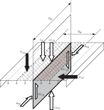


                                 Figure 2.4.6 Loads to be applied to longitudinal bulkhead plating
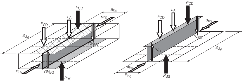


                                 Figure 2.4.7 Loads to be applied to bottom girders


                              4.6.6 The
                                 design shear force for the bottom girder web plating is to include
                                 local and global components.


                                 - 


The design global
                                       shear force is to be taken as Q
                                       D, as defined
                                       in Vol  1, Pt  7, Ch  2,  3.3 Design global loads – Intact conditions or Vol  1, Pt  7, Ch  2,  3.4 Design global loads – Damaged conditions or Residual Strength Assessment (RSA) conditions. If the girder depth is reasonably
                                       small then Q
                                       D may be ignored.


                                 - 


The local shear
                                       force component, QVBG, is due to the difference
                                       between the buoyancy and the inertial forces. It acts in the vertical
                                       direction and is to be taken as:


                                             | 
                                                      
                                                   QVBG
                                                    | 
                                             = | 
                                             εBG (B
                                                   bg
                                                   S
                                                   bg (P
                                                   CD – P
                                                   BS) + [F
                                                   CD] + L A)/2  | 


                              where 


                                       | 
                                                
                                             B
                                             bg
                                              | 
                                       = | 
                                       mean spacing of longitudinal girders or other primary longitudinal
                                             structure, in metres, see Note 2.
                                              | 


                              4.6.7 The
                                 design bending load for bottom girder primary member is to be taken
                                 as:


                               εBG (B
                                 bg 
                                 S
                                 bg (P
                                 CD – P
                                 BS )
                                 + [F
                                 CD] + L
                                 A) kN


                        4.7 Deck girders (DG)


                              4.7.1 The
                                 design normal pressure, P
                                 DG, for deck girder
                                 web plating may be ignored.


                              4.7.2 The
                                 design impulse pressure,  
                                 P
                                 DG, for deck girder web plating
                                 may be ignored, unless these members are subjected to sloshing loads
                                 or similar.


                              4.7.4 The
                                 design vertical load for deck girder webs may be ignored.


                              4.7.5 The
                                 design shear force for the deck girder web plating is to include local
                                 and global components.


                                 - 


The design global
                                       shear force is to be taken as Q
                                       D, as defined
                                       in Vol  1, Pt  7, Ch  2,  3.3 Design global loads – Intact conditions or Vol  1, Pt  7, Ch  2,  3.4 Design global loads – Damaged conditions or Residual Strength Assessment (RSA) conditions. If the girder depth is reasonably
                                       small then Q
                                       D may be ignored.


                                 - 


The local shear
                                       force component, QVDG, is due to the difference
                                       between the buoyancy and the inertial forces. It acts in the vertical
                                       direction and is to be taken as:


                                       | 
                                                
                                             QV
                                             DG
                                              | 
                                       = | 
                                       εBG (B
                                             dg 
                                             S
                                             dg 
                                             P
                                             CD + [F
                                             CD]
                                             + L
                                             A)/2 kN 
                                              | 


                              where 


                                       | 
                                                 εBG
                                              | 
                                       = | 
                                       effectiveness
                                             of the deck girders, i.e. the relative proportion of the load carried
                                             by the deck girders as opposed to other structure such as the deck
                                             beams | 
                                        
                                          | = | 
                                          0,5 | 


                                       | 
                                                
                                             S
                                             dg
                                              | 
                                       = | 
                                       span or length of the longitudinal girder between transverse
                                             bulkheads, in metres | 


                                       | 
                                                
                                             L
                                             A
                                              | 
                                       = | 
                                       load, in kN, from pillar(s) above, assumed zero if there is
                                             none over | 
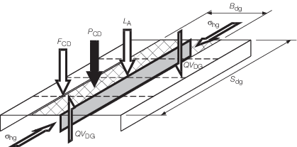


                                 Figure 2.4.8 Loads to be applied to deck girders


                              4.7.7 The
                                 design bending load for the deck girder primary member is to be taken
                                 as:


                              εBG (B
                                 dg 
                                 S
                                 dg 
                                 P
                                 CD + [F
                                 CD]
                                 + L
                                 A) kN.


                        4.8 Longitudinal stringers (ST)


                              4.8.1 This
                                 sub-Section covers stringers supporting side shell plating, horizontal
                                 girders on longitudinal bulkheads and also covers horizontal diaphragms
                                 fitted between a double skin. The design loads are illustrated in Figure 2.4.9 Design loads for longitudinal stringers


                              4.8.2 The
                                 design normal pressure, P
                                 ST, for the web plating
                                 of stringer may be ignored unless the stringer forms part of a tank
                                 boundary or watertight subdivision, i.e. a watertight horizontal diaphragm.
                                 In this case the design pressure is to be taken as the greater of


                                 - 


                                       P
                                       tk kN/m2 (Deep Tank, if applicable), see 
                                       Vol  1, Pt  7, Ch  2,  5.1 Deck structures (DK) 5.1.4


                                 - 


                                       P
                                       da kN/m2 (WT subdivision, only if applicable and for loading conditions
                                       which represent damaged situations), see 
                                       Vol  1, Pt  7, Ch  2,  5.1 Deck structures (DK) 5.1.4.


                                 - 


5,0 (minimum value
                                       for no direct loading).


                              4.8.3 The
                                 design impulse pressure,  
                                 P
                                 ST, for the web plating of stringer
                                 may be ignored, unless these members are subjected to sloshing loads
                                 or similar.


                              4.8.5 The
                                 design transverse load, LT
                                 ST, acting on the
                                 web plating of horizontal diaphragms is to be based on the pressure
                                 loads acting on the plating of the inner skin or longitudinal bulkhead P
                                 LB (outwards) and the side shell P
                                 SS (inwards). The design transverse load, LT
                                 ST,
                                 is to be taken as the lesser of:


                                 - 


–εST 
                                       B
                                       st 
                                       S
                                       st 
                                       P
                                       SS kN


                                 - 


–εST 
                                       B
                                       st 
                                       S
                                       st 
                                       P
                                       LB kN


                              where 


                                       | 
                                                εST
                                              | 
                                       = | 
                                       effectiveness
                                             of the horizontal diaphragms, i.e. the relative proportion of the
                                             load carried by the horizontal diaphragms as opposed to other structure
                                             such as the transverse web or normal frames | 
                                        
                                          | = | 
                                          0,5 | 


                                       | 
                                                
                                             H
                                             st
                                              | 
                                       = | 
                                       mean spacing, in metres, of stringers (or horizontal girders)
                                             and other primary horizontal structure, i.e. decks or similar | 


                                 P
                                 SS is to be taken as the
                                 side shell pressure at the height of the stringer, see 
                                 Vol  1, Pt  7, Ch  2,  3.6 External shell pressures 3.6.1. P
                                 SS is
                                 to be ignored for horizontal girders attached to longitudinal bulkheads.


                                 P
                                 LB is to be taken as the longitudinal
                                 bulkhead normal pressure at the height of the horizontal girder, see 
                                 Vol  1, Pt  7, Ch  2,  4.5 Longitudinal bulkhead structures (LB) 4.5.1 This is only
                                 required for longitudinal bulkheads that form part of a deep tank
                                 or watertight boundary.


                                 Note Where the horizontal diaphragm is part of a longitudinally
                                    stiffened structure with regular transverse webs, the mean spacing H
                                    st may be based on the longitudinal spacing. For
                                    grillage or transversely stiffened systems then the spacing is to
                                    be taken as originally stated.


                              4.8.6 The
                                 design transverse load, LT
                                 ST, for stringers
                                 and horizontal girders may be ignored.


                              4.8.7 The
                                 design shear force, QT
                                 ST, in the stringer
                                 web due to hydrostatic, hydrodynamic or tank loading acts in the transverse
                                 direction is to be taken as the greater of:


                                 - 


εST 
                                       H
                                       st 
                                       S
                                       st 
                                       P
                                       SS/2


                                 - 


εST 
                                       H
                                       st 
                                       S
                                       st 
                                       P
                                       LB/2


                              where 


                                       | 
                                                
                                             H
                                             st
                                              | 
                                       = | 
                                       mean spacing, in metres, of stringers (or horizontal girders)
                                             and other primary horizontal structure, i.e. decks or similar. | 


                              4.8.8 The
                                 design bending load for the deck girder primary member is to be taken
                                 as:


                                 - 


εST 
                                       H
                                       st 
                                       S
                                       st (P
                                       SS – P
                                       LB)


                              where 


                                       | 
                                                
                                             H
                                             st
                                              | 
                                       = | 
                                       mean spacing, in metres, of stringers (or horizontal girders)
                                             and other primary horizontal structure, i.e. decks or similar. | 


             |