
Section
5 Design load systems for structural components or longitudinally
ineffective material
5.1 Deck structures (DK)
5.1.2 For
weather decks and interior decks subjected to cargo loads or other
pressure loading then the following design pressure is to be used
for the plating and stiffeners if it is greater than that given in Vol 1, Pt 7, Ch 2, 5.1 Deck structures (DK) 5.1.1:
where
W
cd is
the static pressure exerted by the cargo, payload, stores or equipment
on the deck as specified by the designer in kN/m2, see
Vol 1, Pt 7, Ch 2, 2.1 Nomenclature 2.1.2 and see also
Vol 1, Pt 5, Ch 3, 5.4 Loads for decks designed for cargo or heavy equipment loads, Pcd and Wcd 5.4.1
w
f is given in Vol 1, Pt 7, Ch 2, 3.5 Inertial force load combination factor, wf 3.5.1
5.1.4 For
weather or internal decks which form part of a deep tank or watertight
boundary then the pressure loading is to be taken as the greater of
the following if this is greater than the above:
|
P
tk
|
= |
9,81ρ (H
tk – z)
kN/m2 (deep tank, if applicable)
|
|
P
da
|
= |
10(H
da – z) kN/m2 (WT
subdivision, only if applicable and for loading conditions which represent
damaged situations)
|
where
|
ρ
|
= |
specific
density of liquid in the tank, to be taken as not less than 1,025 |
|
z |
= |
distance above
the baseline of the mid depth of the deck plating |
H
tk and H
da are
defined in Vol 1, Pt 7, Ch 2, 2.1 Nomenclature 2.1.2
5.2 Transverse watertight and deep tank bulkheads (BH)
5.2.2 The
design impulse pressure,  P
BH, for the bulkhead plating and
stiffeners may be ignored, unless these members are likely to be subjected
to significant sloshing loads or similar.
P
BH, for the bulkhead plating and
stiffeners may be ignored, unless these members are likely to be subjected
to significant sloshing loads or similar.
5.2.3 The
design transverse load, LT
BH, due to hydrostatic
and hydrodynamic compressive loading is to be taken as follows:
|
LT
BH
|
= |
–εBH
P
SS
H
bh
S
bh kN
|
where
|
S
bh
|
= |
half the longitudinal distance between adjacent transverse bulkheads,
in metres |
|
εBH
|
= |
effectiveness
of the bulkhead, i.e. the relative proportion of the load carried
by the bulkhead as opposed to other structure such as decks |
εBH may be taken as 0,5
alternatively
εBH may be taken as
|
εBH
|
= |
H
bh/(2S
bh) for H
bh < S
bh
|
|
and |
= |
1 – S
bh/(2H
bh) for H
bh > S
bh
|
P
SS is to be taken at the
mid height of the H
bh depth, P
SS is defined in Vol 1, Pt 7, Ch 2, 3.6 External shell pressures 3.6.1
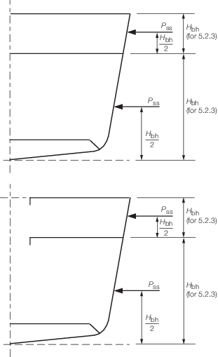
Figure 2.5.1 Design parameter H
bh for transverse
loads
5.2.4 The
design vertical load, LV
BH, supported by the
transverse bulkheads is to be based on the pressure loads acting on
the plating of the supported deck over, P
CD,
the local inertial forces, [F
CD], and the
bulkhead loads above, L
A. The design vertical
load is to be taken as
|
LV
BH
|
= |
–(B
bh
S
bh
P
CD + [F
CD] + L
A) kN
|
where
|
B
bh
|
= |
breadth of the deck supported by the bulkhead, in metres |
P
CD is defined in Vol 1, Pt 7, Ch 2, 5.1 Deck structures (DK) 5.1.2
5.2.5 Normally,
the design shear force, QVBH, may be ignored
for bulkhead plating. However, if the structural arrangement or load
paths are such that significant shear load is carried by the bulkhead,
then it should be considered, e.g. when the bulkhead is not continued
down to the bottom shell. In this case the design shear force, acting
in the vertical direction, is to be taken as
QVBH = LV
BH /2
kN
where
LV
BH is given
in Vol 1, Pt 7, Ch 2, 5.2 Transverse watertight and deep tank bulkheads (BH) 5.2.4
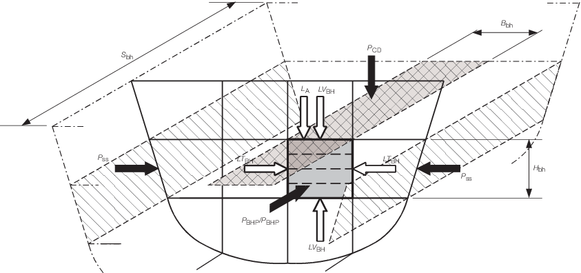
Figure 2.5.2 Design loads for bulkheads
5.3 Deckhouses, bulwarks and superstructures (DH)
5.3.1 The
design normal pressure, P
DH, for the plating
and stiffeners of deckhouses, bulwarks and the first tier and above
of superstructures is given by:
5.3.2 For
the side plating and longitudinal bulkheads of deckhouses and superstructures,
the design vertical load, LV
DH, at each intersecting
deck level is to be taken as follows: LV
DH =
–εDH (S
dh
B
dh
P
CD + L
A +
[F
CD]) kN
where
|
P
CD
|
= |
basic deck design pressure, as appropriate, plus any other local
loadings directly above the pillar, in kN/m2
|
|
εDH
|
= |
effectiveness
of the side plating or longitudinal bulkhead, i.e. the relative proportion
of the load carried by this plating as opposed to other structure
such as the transverse bulkheads |
| = |
0,5 |
S
dh
B
dh is
the effective deck area supported by the deckhouse side plating or
longitudinal bulkheads and can be taken as follows:
|
B
dh
|
= |
mean spacing of longitudinal bulkheads, side shell or effectively
supported longitudinal girders, in metres. |
|
S
dh
|
= |
span or length of the side plating or longitudinal bulkhead
between major deckhouse transverse bulkheads, in metres. |
5.3.3 For
transverse bulkheads of deckhouses and superstructures, the design
vertical load, LV
DH, at each intersecting
deck level is to be taken as follows:
|
LV
DH
|
= |
–εDH (S
dh
B
dh
P
CD + L
A +
[F
CD]) kN
|
where
|
εDH
|
= |
efficiency
of the transverse bulkheads i.e. the relative proportion of the load
carried by the transverse bulkheads as opposed to other structure
such as the side plating |
| = |
0,5 |
S
dh
B
dh is
the effective deck area supported by the transverse bulkhead and can
be taken as follows:
|
S
dh
|
= |
mean spacing of transverse bulkheads, in metres. |
|
B
dh
|
= |
breadth of the transverse bulkhead, in metres. |
5.3.4 For
decks of deckhouses, the design transverse load, LT
DH,
at each deck level may normally be ignored.
5.4 Transverse floors (FL)
5.4.1 The
design normal pressure, P
FL, for the web plating
of floors of double bottom or single bottom structures is to be taken
as the greater of the following:
-
P
tk kN/m2 (Deep tank floor).
-
P
da kN/m2 (WT subdivision, only if applicable and for loading conditions
which represent damaged situations).
-
5 kN/m2 (minimum
value).
where
P
da and P
tk are defined inVol 1, Pt 7, Ch 2, 5.1 Deck structures (DK) 5.1.4
5.4.2 The
design impulse pressure,  P
FL, for the web plating of floors
may be ignored, unless these members are subjected to sloshing loads
or similar.
P
FL, for the web plating of floors
may be ignored, unless these members are subjected to sloshing loads
or similar.
5.4.3 The
design vertical load, LV
FL, for the floors
is to be based on the pressure loads acting on the plating of the
inner bottom P
CD (downwards) and the bottom
shell P
BS (upwards), the local inertial forces
[F
CD] and pillar bulkhead loads above L
A. The design vertical load, LV
FL, is
to be taken as:
|
LV
FL
|
= |
–εFLV ( 
 (P
CD – P
BS)
+ [F
CD] + L
A) kN (P
CD – P
BS)
+ [F
CD] + L
A) kN
|
where
|
εFLV
|
= |
effectiveness
of the floors in the vertical direction, i.e. the relative proportion
of the load carried by the transverse floors as opposed to bottom
girders, etc. |
| = |
1,0 for the floor halfway between transverse
bulkheads |

|
= |
breadth of the transverse
floor between longitudinal bulkheads or side shell(s), in metres.
NOTE  may be full breadth may be full breadth
|
P
BS is defined in Vol 1, Pt 7, Ch 2, 4.1 Bottom shell structures (BS) 4.1.2
P
CD is defined in Vol 1, Pt 7, Ch 2, 5.1 Deck structures (DK) 5.1.2
Note
- For single bottom floors P
CD is likely
to be zero.
- It may be necessary to take account of the impact loading on the
bottom plating in the derivation of LVFL and QVFL.
5.4.4 The
design transverse load, LT
FL, for the floor
plating due to hydrostatic and hydrodynamic compressive loading is
to be taken as follows:
|
LT
FL
|
= |
–εFLT
P
SS
H
d
 kN kN
|
where
|
εFLT
|
= |
effectiveness of the floors in the transverse direction, i.e.
the relative proportion of the load carried by the floor plating as
opposed to other bottom structure |
| = |
0,3f
b for double bottom
structures
|
| = |
0,5f
b for single bottom
structures
|
|
f
b
|
= |
2,0 for bottom structures where transverse elastic buckling
of outer bottom plating is likely |
| = |
3,0 for bottom structures where transverse
elastic buckling of inner and outer bottom plating is likely |
| = |
1,0 otherwise |
P
SS and H
d are
to be taken as the values defined for the bottom structure in Vol 1, Pt 7, Ch 2, 4.1 Bottom shell structures (BS) 4.1.5
5.4.5 The
design shear force, QVFL, for the floor web
plating due to local loading acts in the vertical direction and is
to be taken as:
|
QVFL
|
= |
εFLV (
 (P
CD – P
BS)
+ [F
CD] + L
A)/2 kN (P
CD – P
BS)
+ [F
CD] + L
A)/2 kN
|
5.4.6 The
design bending load for bottom floor primary member is to be taken
as LV
FL.
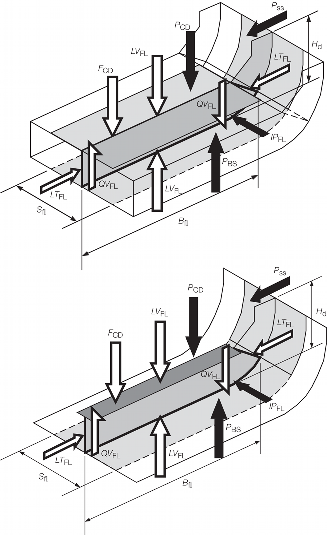
Figure 2.5.3 Loads to be applied to transverse
floors
5.5 Side frames and web frames (SF)
5.5.1 This
sub-Section covers side frames, web frames and frames supporting longitudinal
bulkheads.
5.5.2 The
design normal pressure, P
SF, for the web plating
of side frames may be ignored.
5.5.3 The
design impulse pressure,  P
SF, for the web plating of side
frames may be ignored, unless these members are subjected to sloshing
loads or similar.
P
SF, for the web plating of side
frames may be ignored, unless these members are subjected to sloshing
loads or similar.
5.5.4 The
design vertical load, LV
SF, for the side frames,
including the attached plating, is to be based on the pressure loads
acting on the plating of the supported deck over, P
CD,
the local inertial forces, [F
CD], and side
frame loads above, L
A. The design vertical
load is to be taken as:
|
LVSF
|
= |
– (B
fr
S
fr
P
CD + [F
CD] + L
A) kN
|
where
|
B
fr
|
= |
breadth of the deck supported by the side frame, in metres |
P
CD is defined in Vol 1, Pt 7, Ch 2, 5.1 Deck structures (DK) 5.1.2
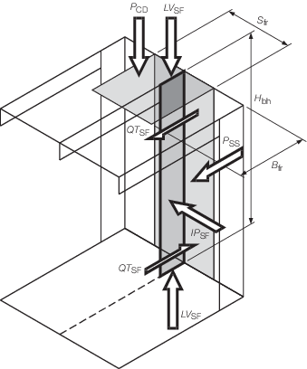
Figure 2.5.4 Loads to be applied to side frames
5.5.5 The
design transverse load, LT
SF, may be ignored
for the side frames.
5.5.6 The
design shear force, QT
SF, for the side frame
web plating due to local loading acts in the transverse direction
and is to be taken as:
|
QT
SF
|
= |
H
fr
S
fr
P
SS/2 kN
|
where
P
SS is to be taken at the
mid height of the side frame, P
SS is defined
in Vol 1, Pt 7, Ch 2, 3.6 External shell pressures 3.6.1
NOTE
It may be necessary to take account of the impact loading on
the side frame plating in the derivation of QT
SF.
5.5.7 The
design bending load for side frame or web frame primary member is
to be taken as:
H
fr
S
fr
P
SS for frames attached to side shell
H
fr
S
fr
P
LB for
frames attached to longitudinal bulkheads.
5.6 Deck beams (BM)
5.6.1 This
sub-Section covers deck beams and deep transverse beams supporting
deck structure.
5.6.2 The
design normal pressure, P
BM, for the web plating
of deck beams may be ignored.
5.6.3 The
design impulse pressure,  P
BM, for the web plating of deck
beams may be ignored, unless these members are subjected to sloshing
loads or similar.
P
BM, for the web plating of deck
beams may be ignored, unless these members are subjected to sloshing
loads or similar.
5.6.4 The
design vertical load, LV
BM, for the deck beam
may be ignored.
5.6.6 The
design shear force, QVBM, for the deck beam
web plating is to be based on the pressure loads acting on the plating
of the deck P
CD (downwards), the local inertial
forces [F
CD] and pillar bulkhead loads above L
A. The shear force acts in the vertical direction
and is to be taken as:
|
QVBM
|
= |
(B
bm
S
bm
P
CD + [F
CD] + L
A )/2
kN
|
where
|
B
bm
|
= |
span of the deck beams between longitudinal bulkheads, pillars
or side shell, in metres |
P
CD is defined in Vol 1, Pt 7, Ch 2, 5.1 Deck structures (DK) 5.1.2
5.6.7 The
design bending load for deck beam primary member is to be taken as:
-
(B
bm
S
bm
P
CD + [F
CD] + L
A) kN
5.7 Pillars (PI)
5.7.1 The
design load,  , supported by the pillar is to be taken as: , supported by the pillar is to be taken as:

|
= |
–(S
pi
B
pi
P
CD + L
A + [F
CD]) kN
|
where
|
P
CD
|
= |
inertial deck design pressure, as appropriate, plus any other
local loadings directly above the pillar, in kN/m2. Where
the pillar supports a deck area over which the design pressure varies,
then the summation of the these loads is to be used, see
Vol 1, Pt 7, Ch 2, 5.1 Deck structures (DK) 5.1.2
|
B
pi
S
pi is
the effective deck area supported by the pillar bulkhead
|
S
pi
|
= |
mean spacing of girders supported by the pillars, longitudinal
bulkheads or side shell, in metres |
 is not to be taken less than 5 kN. is not to be taken less than 5 kN.
5.7.2 When
any of the conditions below are satisfied then the pillar load should
be derived using direct calculation methods:
- where the structural arrangement is complex;
- where it is considered that the load in the pillar will not be
accurately represented by the above formulae, e.g. pillars supporting
decks in way of the ends of a long superstructure block;
- where the pillar is not supported underneath by the double bottom
or substantial structural members.
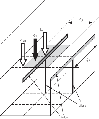
Figure 2.5.6 Loads supported by a pillar
5.8 Pillar bulkheads (PB)
5.8.1 The
vertical in-plane compressive load supported by a pillar bulkhead
is to be taken as:
|
LV
PB
|
= |
– (S
pb
B
pb
P
CD + L
A + [F
CD]) kN
|
where
|
L
A
|
= |
appropriate portion of the load or loads, in kN, from pillar(s)
or bulkhead(s) above, assumed zero if there is none over, may be taken
as  for the supported pillar or LV
PB for
the supported bulkhead for the supported pillar or LV
PB for
the supported bulkhead
|
S
pb, B
pb is
the effective deck area supported by the pillar bulkhead and can be
taken as follows:
-
For longitudinal
pillar bulkheads, see
Figure 2.5.7 Loads supported by a pillar bulkhead:
|
B
pb
|
= |
mean spacing of longitudinal bulkheads, side shell or effectively
supported longitudinal girders, in metres |
|
S
pb
|
= |
length of the pillar bulkhead between major transverse bulkheads
or effectively supported transverse web frames or similar, in metres |
-
For transverse
pillar bulkheads:
|
S
pb
|
= |
mean spacing of transverse bulkheads or effectively supported
transverse web frames or similar, in metres |
|
B
pb
|
= |
breadth of the pillar bulkhead between major longitudinal bulkheads
or the side shell, in metres. |
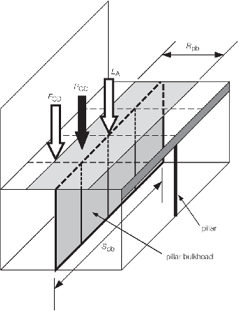
Figure 2.5.7 Loads supported by a pillar bulkhead
5.8.2 When
any of the conditions below are satisfied then the pillar bulkhead
load should be derived using direct calculation methods:
- where the structural arrangement is complex;
- where it is considered that the load in the pillar bulkhead will
not be accurately represented by the above formulae, e.g. pillar bulkheads
supporting decks in way of the ends of a long superstructure block;
- where the pillar bulkhead is not supported underneath by the double
bottom or substantial structural members.
|