
Section
3 Structural idealisation
3.1 General
3.1.1 The scantling
formulae in the Rules are normally based on elastic or plastic theory
using simple beam models supported at one or more points and with
varying degrees of fixity at the ends, in association with an appropriate
concentrated or distributed load for steel and aluminium craft.
3.1.2 Apart from
a local requirement for web or flange thicknesses, the stiffener,
beam or girder strength is defined by a section modulus and moment
of inertia requirement.
3.1.3 For the
derivation of scantlings for fibre composite structures, the formulae
are based on equivalent load carrying capability, with limitations
on both allowable stress and strain, in addition to deflection controls.
3.2 Geometric properties of sections
3.2.1 The symbols used in this sub-Section are defined as follows:
|
b
|
= |
the actual width, in metres, of the load-bearing plating, i.e.
one-half of the sum of spacings between parallel adjacent members or equivalent
supports |
|
t
p
|
= |
the thickness, in mm, of the attached plating. Where this varies,
the mean thickness over the appropriate span is to be used. |
Table 2.3.1 Values of factor f
|
|
f
|
|
f
|
| 0,5
|
0,19
|
3,5
|
0,69
|
| 1,0
|
0,30
|
4,0
|
0,76
|
| 1,5
|
0,39
|
4,5
|
0,82
|
| 2,0
|
0,48
|
5,0
|
0,88
|
| 2,5
|
0,55
|
5,5
|
0,94
|
| 3,0
|
0,62
|
6,0 and above
|
1,00
|
NOTE
Intermediate values to be obtained by linear
interpolation.
|
3.2.2 The effective geometric properties of rolled or built sections may be
calculated directly from the dimensions of the section and associated effective area of
attached plating. Where the web of the section is not normal to the attached plating,
and the angle exceeds 20o, the properties of the section are to be determined
about an axis parallel to the attached plating.
3.2.3 The geometric properties of rolled or built stiffener sections and of
swedges are to be calculated in association with effective area of attached load bearing
plating of thickness t
pmm and of width as given by Pt 6, Ch 3, 1.10 Effective width of attached plating or Pt 7, Ch 3, 1.11 Effective width of attached plating for steel and aluminium alloy construction
respectively. In no case, however, is the width of plating to be taken as greater than
either the spacing of the stiffeners or the width of the flat plating between swedges,
whichever is appropriate. The thickness, t
p, is the actual thickness of the attached plating. Where this varies, the
mean thickness over the appropriate span is to be used.
3.2.4 The effective section modulus of a corrugation over a spacing, s
c, is to be calculated from the dimensions and, for symmetrical corrugations,
may be taken as:
where d
w, b, t
p, c and t
w are measured, in mm, and are as shown in Figure 2.3.1 Corrugation. The value of b is to be taken not
greater than:
 for welded corrugations for welded corrugations
 for cold formed corrugations for cold formed corrugations
where σ0 is defined in Pt 3, Ch 3, 1.2 General.
The value of θ is not to be taken less than 40o. The moment of
inertia is to be calculated from:
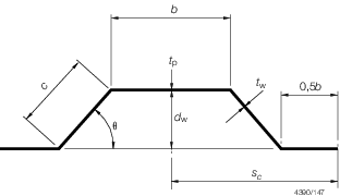
Figure 2.3.1 Corrugation
3.2.5 The section modulus of a double plate bulkhead over a spacing b may
be calculated as:
where d
w, b, t
p and t
w are measured, in mm, and are as shown in Figure 2.3.2 Double plate bulkhead.
3.2.6 The effective stiffness and the effective stress response of profiles of which the web
has openings with a height more than 50 per cent of the web depth, or where the width of
intact plate between openings is less than the maximum size of the openings, are to be
determined by direct calculation based on the actual arrangement of the openings.
3.2.7 The effective section modulus of a fabricated section may be taken as:
where
|
a
|
= |
the area of the face plate of the member, in cm2
|
|
d
w
|
= |
the depth, in mm, of the web between the inside of the face plate
and the attached plating. Where the member is at right angles to a line of
corrugations, the minimum depth is to be taken |
|
t
w
|
= |
the thickness of the web of the section, in mm |
|
A
|
= |
the area, in cm2, of the attached plating, see
Pt 3, Ch 2, 3.2 Geometric properties of sections 3.2.8. If the calculated value of A is less
than the face area a, then A is to be taken as equal to a
|
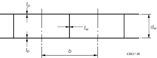
Figure 2.3.2 Double plate bulkhead
3.2.8 The geometric properties of primary support members (i.e. girders,
transverses, webs, stringers, etc.) are to be calculated in association with an
effective area of attached load bearing plating, A, determined as follows:
-
For a member attached to plane plating:
where f is as defined in Pt 3, Ch 2, 3.2 Geometric properties of sections 3.2.1.
-
For a member attached to corrugated plating and parallel to the
corrugations:
(See
Figure 2.3.1 Corrugation)
-
For a member attached to corrugated plating and at right angles to
the corrugations:
-
A is to be taken as equivalent to the area of the face plate of the
member.
3.3 Determination of span point
3.4 Calculation of hull section properties
|