
Section
1 General
1.1 Application
1.2 General
1.2.1 The formulae
contained within this Chapter are to be used in conjunction with the
design loadings from Pt 5 Design and Load Criteria to determine
the Rule scantling requirements.
1.3 Direct calculations
1.3.1 Where the
craft is of unusual design, form or proportions, or where the speed
of the craft exceeds 60 knots the scantlings are to be determined
by direct calculation.
1.3.2 The requirements
of this Chapter may be modified where direct calculation procedures
are adopted to analyse the stress distribution in the primary structure.
1.4 Equivalents
1.4.1 Clasifications
Register (hereinafter referred to as 'LR') will consider direct calculations
for the derivation of scantlings as an alternative and equivalent
to those derived by Rule requirements in accordance with Pt 3, Ch 1, 3 Equivalents.
1.5 Symbols and definitions
1.6 Rounding policy for Rule plating thickness
1.6.1 Where plating
thicknesses as determined by the Rules require to be rounded then
this is to be carried out to the nearest full or half millimetre,
with thicknesses 0,75 and 0,25 being rounded up.
1.7 Dimensional tolerance
1.7.1 Dimensional
tolerances for materials are to be in accordance with Ch 8 Aluminium Alloysof the Rules for the Manufacture,
Testing and Certification of Materials (hereinafter referred
to as the Rules for Materials), or an acceptable National or International
Standard.
1.7.2 The under
thickness tolerance acceptable for classification is to be considered
as the lower limit of a range of thickness tolerance which could be
found in the normal production of a conventional rolling mill manufacturing
material, on average, to the nominal thickness.
1.7.4 The minus
tolerance on sections (except for wide flats) is to be in accordance
with a National or International Standard.
1.7.5 The thickness
of plates and strip is to be measured at random locations whose distance
from an edge is to be at least 25 mm. Local surface depressions resulting
from imperfections and ground areas resulting from the elimination
of defects may be disregarded provided that they are in accordance
with the requirements of a National or International Standard.
1.7.6 The responsibility
for maintaining the required tolerances and making the necessary measurements
rests with the manufacturer/Builder. Occasional checking by the Surveyor
does not absolve the manufacturer/Builder from the responsibility.
1.8 Material properties
1.8.1 The basic
grade of aluminium alloy is taken as marine grade 5083-0 with the
following mechanical properties:
|
|
N/mm2
|
| 0,2 per cent proof stress
(minimum)
|
125
|
| Tensile strength
|
260
|
| Modulus of elasticity
|
69 x 103
|
1.8.2 Where other
alloy grades with differing mechanical properties are to be used,
due allowance is given in the determination of the Rule requirement
for plating thickness, section modulus, inertia and cross-sectional
area by use of the following correction factors:
-
Plating thickness
factor = 
-
Section modulus and
cross section area factor = k
a
where k
a is as defined in Pt 7, Ch 3, 1.5 Symbols and definitions 1.5.1.
1.9 High strength sheet and plate
1.9.1 Particular
attention is to be given to the welding procedures for the welding
of high strength sheet and plate. The 0,2 per cent yield strength
values in the welded condition will, in general, be significantly
less than in the unwelded condition. These reduced values are to be
used in the determination of the Rule scantlings.
1.10 High strength extrusions
1.10.1 The requirements
of Pt 7, Ch 3, 1.9 High strength sheet and plate are to be complied with.
However, special consideration will be given to the use of un-welded
strength properties for use in the determination of the Rule scantlings
provided that suitable compensation is provided in way of welding
on the face of the stiffener. This compensation can be provided by
butt-straps or other acceptable arrangements, see also
Pt 7, Ch 2, 4.25 Extruded `planking'.
1.10.2 The application
of high strength extrusions is in general limited to superstructures,
deckhouses, decks and bulkheads. Special consideration will be given
to their use in other areas.
1.10.3 Butt
welds and seams are to be carefully positioned clear of areas of high
stress and where practicable are to be orientated parallel to the
direction of the main stresses.
1.11 Effective width of attached plating
1.11.1 The effective
geometric properties of rolled or built sections are to be calculated
directly from the dimensions of the section and associated effective
area of attached plating. Where the web of the section is not normal
to the actual plating, and the angle exceeds 20o, the properties
of the section are to be determined about an axis parallel to the
attached plating.
1.11.3 The effective
width of attached plating to secondary members b
e is
to be taken as  but not greater than s. σa is
not to be taken as greater than 169 N/mm2 for aluminum
alloy. E, s and σa are as
defined in Pt 7, Ch 3, 1.5 Symbols and definitions 1.5.1. but not greater than s. σa is
not to be taken as greater than 169 N/mm2 for aluminum
alloy. E, s and σa are as
defined in Pt 7, Ch 3, 1.5 Symbols and definitions 1.5.1.
1.11.5 Where
primary stiffening members support areas of plating of the extruded
plank type, or the floating frame system is used, the effect of the
plating attached to the secondary stiffening members is to be ignored
when calculating the actual section modulus and inertia of the primary
stiffening members, i.e. the full section modulus and inertia are
to be provided by the primary stiffening member only, see also
Pt 7, Ch 2, 4.26 Aluminium/steel transition joints.
1.12 Other materials
1.12.1 Special
consideration will be given to the use of materials other than aluminium
alloy. Details of the type of material, the specification to which
it was manufactured and its mechanical properties are to be submitted
for appraisal.
1.13 Fibre reinforced plastic (FRP)
1.14 Convex curvature correction
1.14.1 The thickness
of plating as determined by the Rules may be reduced where significant
curvature exists between the supporting members. In such cases a plate
curvature correction factor may be applied:
|
γ |
= |
plate curvature
factor |
|
|
= |
1 - h/s, and is not to be taken as less than 0,7
|
|
h
|
= |
the
distance, in mm, measured perpendicularly from the chord length s (i.e.
spacing) to the highest point of the curved plating arc between the
two supports.
|
See
Figure 3.1.1 Convex curvature.
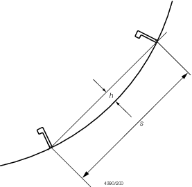
Figure 3.1.1 Convex curvature
1.15 Aspect ratio correction
1.15.1 The thickness
of plating as determined by the Rules may be reduced when the panel
aspect ratio is taken into consideration. In such cases a panel aspect
ratio correction factor may be applied:
|
β |
= |
aspect ratio
correction factor |
|
|
= |
A
R(1
- 0,25A
R) for A
R ≤
2
|
where
|
A
R
|
= |
panel aspect ratio |
|
|
= |
panel length/panel
breadth. |
1.16 Plating general
1.16.1 The requirements
for the thickness of plating, t
p, is, in general,
to be in accordance with the following:
s, γ, β, p, σa are
as defined in Pt 7, Ch 3, 1.5 Symbols and definitions 1.5.1.
1.17 Stiffening general
1.17.1 The requirements
for section modulus, inertia and web area of stiffening members are
in general to be in accordance with the following:
-
Section modulus:
p, s,  e and σa are as defined in Pt 7, Ch 3, 1.5 Symbols and definitions.
-
Inertia:
p, s,  e, and E are as defined in Pt 7, Ch 3, 1.5 Symbols and definitions 1.5.1.
-
Web area:
p, s,  e, and τa are as defined in Pt 7, Ch 3, 1.5 Symbols and definitions 1.5.1.
1.18 Geometric properties and proportions of stiffener sections
1.18.1 From
structural stability and local buckling considerations, the proportions
of stiffening members are, in general, to be in accordance with Table 3.1.2 Stiffener proportions.
1.19 Determination of span point
1.19.1 The effective
length of span,  e, of a stiffening member is generally less
than the overall length,
e, of a stiffening member is generally less
than the overall length,  , by an amount which depends on the design of the end connections.
The span points, between which the value of , by an amount which depends on the design of the end connections.
The span points, between which the value of  e is measured, are to be determined as follows:
-
For rolled or built-up
secondary stiffening members:
The span point is to be taken at the point where the depth of
the end bracket, measured from the face of the secondary stiffening
member, is equal to the depth of the member, see
Figure 3.1.2 Span points. Where there is no end bracket,
the span point is to be measured between primary member webs.
-
For primary support
members:
The span point is to be taken at a point distant, b
e from the end of the member, where
where b
e, b
b, d
w and d
B are as shown in Figure 3.1.2 Span points.
1.19.2 Where
the stiffener member is inclined to a vertical or horizontal axis
and the inclination exceeds 10o, the span is to be measured
along the member.
Table 3.1.1 Section modulus, inertia and web
area coefficients
Load
Model
|
Position
|
Position
|
Web area
coefficient
|
Section modulus
coefficient
|
Inertia
coefficient
|
Application
|
| 1
|
2
|
3
|
ΦA
|
ΦZ
|
ΦI
|
| (a)
|
|
1
2
3
|
1/2
-
1/2
|
1/12
1/24
1/12
|
-
1/384
-
|
Primary
and other members where the end fixity is considered encastre
|
| (b)
|
|
1
2
3
|
1/2
-
1/2
|
1/10
1/10
1/10
|
-
1/288
-
|
Local,
secondary and other members where the end fixity is considered to be
partial
|
| (c)
|
|
1
2
3
|
5/8
-
3/8
|
1/8
9/128
-
|
-
1/185
-
|
Various
|
| (d)
|
|
1
2
3
|
1
-
-
|
1/2
-
-
|
-
-
1/8
|
Various
|
| (e)
|
|
1
2
3
|
1/2
-
1/2
|
-
1/8
-
|
-
5/384
-
|
Hatch
covers, glazing and other members where the ends are simply
supported
|
Table 3.1.2 Stiffener proportions
| Type of
stiffener
|
Requirement
|
| (1) Flat bar
|
Minimum web thickness:
|
| (2) Rolled or built sections
|
(a) Minimum web
thickness:
|
|
|
(b) Maximum unsupported face plate (or
flange) width:
|
| Symbols
|
|
t
w = web thickness of stiffener with unstiffened webs, in mm
d
w = web depth of stiffener, in mm
b
f = face plate (or flange) unsupported width, in mm
t
f = face plate (or flange) thickness, in mm
|
1.19.3 Where
the stiffening member is curved then the span is to be taken as the
effective chord length between span points.
1.19.4 Where
there is a pronounced turn of bilge, chine or the structure is significantly
pitched, the span may be measured as in Figure 3.1.2 Span points.
1.19.5 It is
assumed that the ends of stiffening members are substantially fixed
against rotation and displacement. If the arrangement of supporting
structure is such that this condition is not achieved, consideration
will be given to the effective span to be used for the stiffener.
1.20 Secondary member end connections
1.20.2 Where
bracketed end connections are fitted in accordance with these requirements,
they may be taken into account in determining the effective span of
the member.
1.21 Scantlings of end brackets
1.21.1 Where
a longitudinal strength member is cut at a primary support and the
continuity of strength is provided by brackets, the scantlings of
the end brackets are to be such that their section modulus and effective
cross-sectional area are not less than those of the member. Care is
to be taken to ensure correct alignment of the brackets on each side
of the primary member.
1.21.2 In other
cases the scantlings of the bracket are to be based on the modulus
as follows:
-
Bracket connecting
stiffener to primary member - modulus of the stiffener.
-
Bracket at the head
of a main transverse frame where frame terminates - modulus of the
frame.
-
Brackets connecting
lower deck beams or longitudinals to the main frame in the forward
0,5L
R - modulus of the frame.
-
Elsewhere - the
lesser modulus of the members being connected by the bracket.
1.21.5 The lengths, a and b of the arms are to be measured from the
plating to the toe of the bracket and are to be such that:
-
a + b ≥ 2,0 b
b
-
a ≥
0,8 b
b
-
b ≥
0,8 b
b
where a and b are the actual lengths
of the two arms of the bracket, in mm, measured from the plating to
the toe of the bracket.
 b
b
|
= |

|
|
Z |
= |
the section modulus
of the secondary member, in cm3
|
In no case is  b to be taken as less than twice the web depth
of the stiffener on which the bracket scantlings are to be based.
b to be taken as less than twice the web depth
of the stiffener on which the bracket scantlings are to be based.
1.21.6 The free
edge of the bracket is to be stiffened where any of the following
apply:
-
The section modulus, Z, exceeds 500 cm3.
-
The length of free
edge exceeds 40 times the bracket thickness.
-
The bracket is fitted
at the lower end of main transverse side framing.
1.21.7 Where
a face flat is fitted, its breadth, b
f, is
to be not less than:
but not less than 40 mm
1.21.8 Where
the edge is stiffened by a welded face flat, the cross-sectional area
of the face flat is to be not less than:
-
0,017 k
a
b
f
T
B cm2 for
offset edge stiffening.
-
0,014 k
a
b
f
T
B cm2 for
symmetrically placed stiffening.
|
b
f
|
= |
breadth of face flat, in mm |
|
T
B
|
= |
the thickness of the bracket, in mm |
1.21.9 Where
the stiffening member is lapped onto the bracket, the length of overlap
is to be adequate to provide for the required area of welding. In
general, the length of overlap is not to be less than  , or the depth of stiffener, whichever is the greater. , or the depth of stiffener, whichever is the greater.
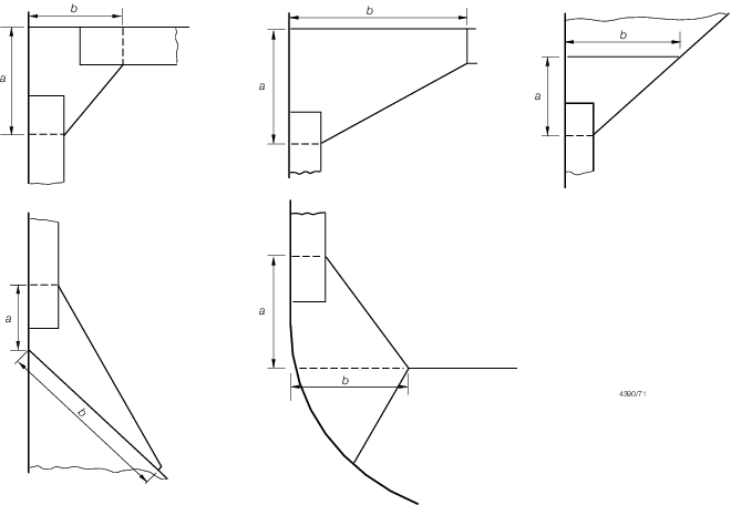
Figure 3.1.3 Stiffener end brackets
1.21.10 Where
the free edge of the bracket is hollowed out, it is to be stiffened
or increased in size to ensure that the modulus of the bracket through
the throat is not less than that of the required straight edged bracket.
1.21.11 The
arrangement of the connection between the stiffener and the bracket
is to be such that at no point in the connection is the actual modulus
reduced to less than that of the stiffener with associated plating.
1.21.12 The
design of end connections and their supporting structure is to be
such as to provide adequate resistance to rotation and displacement
of the joint.
1.22 Primary member end connections
1.22.1 The requirements
for section modulus and inertia (if applicable) of primary members
are given in the appropriate Chapter. The scantling requirements for
primary member end connections in dry spaces and in tanks of all craft
types are generally to comply with the requirements of Pt 7, Ch 3, 1.21 Scantlings of end brackets, taking Z as the section
modulus of the primary member.
1.22.2 Primary
members are to be so arranged as to ensure effective continuity of
strength, and abrupt changes of depth or section are to be avoided.
Where members abut on both sides of a bulkhead, or on other members,
arrangements are to be made to ensure that they are in alignment.
Primary members in tanks are to form a continuous line of support
and wherever possible, a complete ring system.
1.22.3 The members
are to have adequate lateral stability and web stiffening and the
structure is to be arranged to minimise hard spots and other sources
of stress concentration. Openings are to have well rounded corners
and smooth edges and are to be located having regard to the stress
distribution and buckling strength of the panel.
1.22.4 Primary
members are to be provided with adequate end fixity by end brackets
or equivalent structure. The design of end connections and their supporting
structure is to be such as to provide adequate resistance to rotation
and displacement of the joint and effective distribution of the load
from the member.
1.22.5 Where
the primary member is supported by structure which provides only a
low degree of restraint against rotation, the member is generally
to be extended beyond the point of support and thereafter tapered
and/or scarfed into the adjacent structure over a distance generally
not less than two frame spaces.
1.22.6 Where
primary members are subject to concentrated loads, particularly if
these are out of line with the member web, additional strengthening
may be required.
1.22.7 The thickness
of the bracket is to be not less than that of the primary member web.
The free edge of the bracket is to be stiffened.
1.22.8 Where
a deck girder or transverse is connected to a vertical member on the
shell or bulkhead, the scantlings of the latter may be required to
be increased to provide adequate stiffness to resist rotation of the
joint.
1.22.9 Where
a member is continued over a point of support, such as a pillar or
pillar bulkhead stiffener, the design of the end connection is to
be such as to ensure the effective distribution of the load into the
support. Proposals to fit brackets of reduced scantlings, or alternative
arrangements, will be considered.
1.22.10 Connections
between primary members forming a ring system are to minimise stress
concentrations at the junctions. Integral brackets are generally to
be radiused or well rounded at their toes. The arm length of the bracket,
measured from the face of the member, is to be not less than the depth
of the smaller member forming the connection.
1.23 Tank boundary penetrations
1.23.1 Where
structural members pass through the boundary of a tank, and leakage
into the adjacent space could be hazardous or undesirable, full penetration
welding is to be adopted for the members for at least 150 mm on each
side of the boundary. Alternatively a small scallop of suitable shape
may be cut in the member close to the boundary outside the compartment,
and carefully welded all round.
1.24 Web stability
1.24.1 Primary members are to be supported by tripping brackets. The tripping
brackets supporting asymmetrical sections are to be spaced no more than two secondary
frames apart. The tripping brackets supporting symmetrical sections are to be spaced no
more than four secondary frames apart.
1.24.2 Tripping
brackets are in general required to be fitted at the toes of end brackets
and in way of heavy or concentrated loads such as the heels of pillars. See also LR's Guidance Notes for Structural Details.
1.25 Openings in the web
1.25.1 Where
openings are cut in the web, the depth of opening is not to exceed
50 per cent of the web depth, and the opening is to be so located
that the edges are not less than 25 per cent of the web depth from
the face plate. The length of opening is not to exceed the web depth
or 60 per cent of the secondary member spacing, whichever is the greater,
and the ends of the openings are to be equidistant from the corners
of cut-outs for secondary members. Where larger openings are proposed,
the arrangements and compensation required will be specially considered.
1.25.2 Openings
are to have smooth edges and well rounded corners.
1.26 Continuity and alignment
1.26.1 The arrangement
of material is to be such as will ensure structural continuity. Abrupt
changes of shape or section, sharp corners and points of stress concentration
are to be avoided.
1.26.2 Where
members abut on both sides of a bulkhead or similar structure, care
is to be taken to ensure good alignment.
1.26.3 Pillars
and pillar bulkheads are to be fitted in the same vertical line wherever
possible, and elsewhere arrangements are to be made to transmit the
out of line forces satisfactorily. The load at head and heel of pillars
is to be effectively distributed and arrangements are to be made to
ensure the adequacy and lateral stability of the supporting members.
1.26.4 Continuity
is to be maintained where primary members intersect and where the
members are of the same depth, a suitable gusset plate is to be fitted, see
Figure 3.1.4 Primary member intersection.
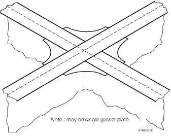
Figure 3.1.4 Primary member intersection
1.26.5 End connections
of structural members are to provide adequate end fixity and effective
distribution of the load into the supporting structure.
1.26.6 The toes
of brackets, etc. are not to land on unstiffened panels of plating.
Special care is to be taken to avoid notch effects at the toes of
brackets, by making the toe concave or otherwise tapering it off, see
also LR's Guidance Notes for Structural Details.
1.26.7 Particular
attention is to be paid to the design of the end bracket toes in order
to minimise stress concentrations. Sniped face plates which are welded
onto the edge of primary member brackets are to be carried well around
the radiused part of the bracket toe and are to incorporate a taper
not exceeding one in three. Where sniped face plates are welded adjacent
to the edge of primary member brackets, adequate cross sectional area
is to be provided through the bracket toe at the end of the snipe.
In general, this area measured perpendicular to the face plate, is
to be not less than 60 per cent of the full cross-sectional area of
the face plate, see
Figure 3.1.5 Bracket toe construction.
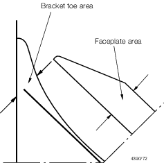
Figure 3.1.5 Bracket toe construction
1.27 Arrangement with offset stiffener
1.27.1 Where
the stiffeners of the double bottom floors and transverse bulkheads
are unconnected to the secondary members and offset from them, see
Figure 3.1.6 Arrangement with offset stiffener, the collar arrangement
for the secondary members are to satisfy the requirements of Pt 7, Ch 3, 1.28 Arrangements at intersection of continuous secondary and primary members. In addition, the fillet welds
attaching the lugs to the secondary members are to be based on a weld
factor of 0,44 for the throat thickness. To facilitate access for
welding the offset stiffeners are to be located 50 mm from the slot
edge furthest from the web of the secondary member. The ends of the
offset stiffeners are to be suitably tapered and softened.
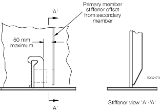
Figure 3.1.6 Arrangement with offset stiffener
1.27.2 Alternative
arrangements will be considered on the basis of their ability to transmit
load with equivalent effectiveness. Details of the calculations made
and testing procedures are to be submitted.
1.28 Arrangements at intersection of continuous secondary and primary
members
1.28.1 Cut-outs
for the passage of secondary members through the webs of primary members,
and the related collaring arrangements, are to be designed to minimise
stress concentrations around the perimeter of the opening and in the
attached hull envelope or bulkhead plating. The critical shear buckling
stress of the panel in which the cut-out is made is to be investigated.
Cut-outs for longitudinals will be required to have double lugs in
areas of high stress.
1.28.2 The cross-sectional areas of connections are to be determined from the load transmitted
through each component in association with its appropriate permissible stress.
1.28.4 Total load, P, transmitted to the primary member from the secondary member is to
be derived by:
where
|
s |
= |
secondary stiffener spacing, mm |
|
S |
= |
primary stiffener spacing, m |
|
p |
= |
design plating pressure, kN/m2 |
|
P |
= |
total load, kN |
1.28.5 The arrangement of lug/collar/direct connection to the primary web
stiffener determines the load apportioned to each component. The effect on each
component of the intersection is to be assessed, as appropriate, for shear and direct
stress. Where the web stiffener is not connected to the secondary member, the load,
P, is transmitted through the lug/collar/direct connection.
1.28.6 The breadth of cut-outs is to be as small as practicable, with the top edge
suitably radiused. Cut-outs are to have smooth edges, and the corner radii are to be as
large as practicable. Where the web depth is greater than 100 mm the corner radii are to
be a minimum of 20 per cent of the breadth of the cut-out or 20 mm, whichever is the
greater, and for large cut-outs greater than 250 mm deep, the web plate connection to
the hull envelope, or bulkhead, should end in a smooth tapered `soft toe'. Recommended
shapes of cut-out are shown in Figure 3.1.7 Cut-outs and connections, but consideration will be given to other shapes
on the basis of maintaining equivalent strength and minimising stress concentration,
see also LR's Guidance Notes for Structural Details.
1.28.7 Consideration
is to be given to the provision of adequate drainage and unimpeded
flow of air and water when designing the cut-outs and connection details.
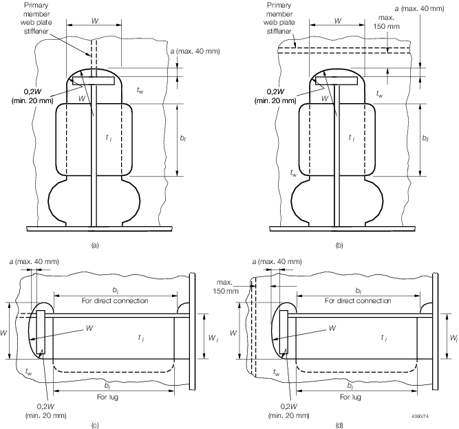
Figure 3.1.7 Cut-outs and connections
1.28.8 Asymmetrical
secondary members are to be connected on the heel side to the primary
member web plate. Additional connection by lugs on the opposite side
may be required.
1.28.9 Symmetrical
secondary members are to be connected by lugs on one or both sides,
as necessary.
1.28.10 Where
the primary member stiffener is connected to the secondary member
it is to be aligned with the web of the secondary member, except where
the face plate of the latter is offset and abutted to the web, in
which case the stiffener connection is to be lapped.
1.28.11 Fabricated
longitudinals having the face plate welded to the underside of the
web, leaving the edge of the web exposed, are not recommended for
side shell and longitudinal bulkhead longitudinals. Where it is proposed
to fit such sections, a symmetrical arrangement of connection to transverse
members is to be incorporated. This can be achieved by fitting backing
structure on the opposite side of the transverse web or bulkhead.
1.28.12 Where
a bracket is fitted to the primary member web plate in addition to
a connected stiffener it is to be arranged on the opposite side to,
and in alignment with the stiffener. The arm length of the bracket
is to be not less than the depth of the stiffener, and its cross-sectional
area through the throat of the bracket is to be included in the calculation
of the area of the primary web stiffener in way of the connection.
1.28.13 Alternative
arrangements will be considered on the basis of their ability to transmit
load with equivalent effectiveness. Details of the calculations made
and testing procedures are to be submitted.
1.29 Openings
1.29.1 Manholes,
lightening holes and other cut-outs are to be avoided in way of concentrated
loads and areas of high shear. In particular, manholes and similar
openings are not to be cut in vertical or horizontal diaphragm plates
in narrow cofferdams or in floors and double bottom girders close
to their span ends, or below the heels of pillars, unless the stresses
in the plating and the panel buckling characteristics have been calculated
and found satisfactory.
1.29.2 Manholes,
lightening holes and other openings are to be suitably framed and
stiffened where necessary.
1.29.3 Air and
drain holes, notches and scallops are to be kept at least 200 mm clear
of the toes of end brackets and other areas of high stress. Openings
are to be well rounded with smooth edges. Closely spaced scallops
are not permitted. Widely spaced air or drain holes may be accepted,
provided that they are of elliptical shape, or equivalent, to minimise
stress concentration and are, in general, cut clear of the weld connection.
1.30 Fittings and attachments, general
1.31 Bilge keels and ground bars
1.31.1 It is
recommended that bilge keels are not to be fitted in the forward 0,3L
R region on ships intended to navigate in ice conditions.
1.31.2 Bilge
keels are to be attached to a continuous ground bar as shown in Figure 3.1.8 Bilge keel construction. Butt welds in shell plating,
ground bar and bilge keels are to be staggered.
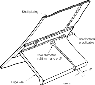
Figure 3.1.8 Bilge keel construction
1.31.3 The thickness
of the ground bar is to be not less than the thickness of the bottom
shell or 8 mm, whichever is the greater, but need not be taken as
greater than 15 mm.
1.31.4 The material
class, grade and quality of the ground bar are to be similar to those
of the adjacent shell plating.
1.31.5 The ground
bar is to be connected to the shell with a continuous fillet weld
and the bilge keel to the ground bar with a light continuous fillet
weld.
1.31.6 Direct
connection between ground bar butt welds and shell plating, and between
bilge keel butt welds and ground bar is to be avoided.
1.31.7 The end
details of bilge keels and intermittent bilge keels, where adopted,
are to be as shown in Figure 3.1.9 Bilge keel end design.
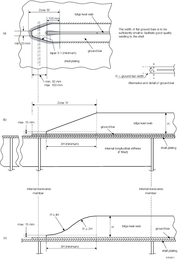
Figure 3.1.9 Bilge keel end design
1.31.10 An
internal transverse support is to be positioned as close as possible
to halfway between the end of the bilge keel web and the end of the
ground bar, see
Figure 3.1.9 Bilge keel end design(b).
1.31.12 For
craft over 65 m in length, L
R, holes are to
be drilled in the bilge keel butt welds. The size and position of
these holes are to be as illustrated in Figure 3.1.8 Bilge keel construction. Where the butt weld has been subject to non-destructive
examination the stop hole may be omitted.
1.31.14 Within
zone 'B' (see
Figure 3.1.9 Bilge keel end design(a)),
welds at the ends of the ground bar and the bilge plating, and at
the ends of the bilge keel web and ground bar, are to have weld factors
of 0,44 and 0,34 respectively. These welds are to be ground and to
blend smoothly with the base materials.
1.31.15 A plan
of the bilge keels is to be submitted for approval of material grades,
welded connections and detail design.
1.32 Other fittings and attachments
1.32.1 Gutterway
bars at the upper deck are to be so arranged that the effect of main
hull stresses on them is minimised.
1.32.2 Minor
attachments, such as pipe clips, staging lugs and supports, are generally
to be kept clear of toes of end brackets, corners of openings and
similar areas of high stress. Where connected to asymmetrical stiffeners,
the attachments may be in line with the web providing the fillet weld
leg length is clear of the offset face plate or flange edge. Where
this cannot be achieved the attachments are to be connected to the
web, and in the case of flanged stiffeners they are to be kept at
least 25 mm clear of the flange edge. On symmetrical stiffeners, they
may be connected to the web or to the centreline of the face plate
in line with the web.
1.32.3 Where
necessary in the construction of the craft, lifting lugs may be welded
to the hull plating but they are not to be slotted through. Where
they are subsequently removed, this is to be carried out by mechanical
cutting close to the plate surface, and the remaining material and
welding ground off. After removal the area is to be carefully examined
to ensure freedom from cracks or other defects in the plate surface.
|