
Section
4 Joints and connections
4.1 General
4.1.1 Requirements
are given in this Chapter for welding connection details, aluminium/steel
transition joints, aluminium/wood connection, riveting of light structure
and chemical bonding.
4.1.2 Welded
joints are to be detailed such that crevices or inaccessible pockets
capable of retaining dirt or moisture are avoided. Where cavities
are unavoidable, they are to be sealed by welding or protective compounds
or made accessible for inspection and maintenance.
4.2 Weld symbols
4.2.1 Weld symbols,
where used, are to conform to a recognised National or International
Standard. Details of such Standards are to be indicated on the welding
schedule, which is to be submitted for appraisal.
4.3 Welding schedule
4.3.1 A welding
schedule containing not less than the following information is to
be submitted:
-
Weld throat thickness
or leg lengths.
-
Grades, tempers,
and thicknesses of materials to be welded.
-
Locations, types
of joints and angles of abutting members.
-
Reference to welding
procedures to be used.
-
Sequence of welding
of assemblies and joining up of assemblies.
4.4 Butt welds
4.4.1 All structural
butt joints are to be made by means of full penetration welds and,
in general, the edges of plates to be joined by welding are to be
bevelled on one or both sides of the plates. Full details of the proposed
joint preparation are to be submitted for approval, see also
Pt 7, Ch 2, 4.19 Joint preparation.
4.4.2 Where butt
welds form a T-junction, the leg of the T is, where practicable, to
be completed first including any back run. During the welding operation
special attention is to be given to the completion of the weld at
the junction, which is to be chipped back to remove crater cracks,
etc. before the table is welded.
4.4.3 For guidance
purposes, a number of typical joint preparations for TIG and MIG welding
are shown in Table 2.4.1 Typical joint preparations for TIG
welding of aluminium alloys and Table 2.4.2 Typical joint preparations for
semi-automatic MIG welding respectively.
Table 2.4.1 Typical joint preparations for TIG
welding of aluminium alloys
| Thickness
(mm)
|
Joint
design
|
Welding
position/comments
|
| 2,5 –
3,0
|

|
Flat
Horizontal
Vertical
Overhead
|
| 3,0 –
10,0
|

|
Flat and
Vertical
V = 60o
Horizontal and
Overhead
V = 90o –
110o
|
| Symbols and definitions
|
|
V
w
|
= |
weld preparation angle, in degrees |
|
Table 2.4.2 Typical joint preparations for
semi-automatic MIG welding
| Thickness
(mm)
|
Joint
design
|
Welding
position/comments
|
| 5,0 –
6,5
|
|
Flat
|
| 7,0 –
15,0
|

|
Flat
Horizontal
Vertical
Overhead
One sided welding with
temporary backing
|
| 12,0 –
25,0
|

|
All
positions
|
| Symbols and definitions
|
|
t
p
|
= |
plate thickness, in mm |
|
4.5 Fillet welds
4.5.2 The length, in mm, of any weld fillet in any intermittent welding arrangement is to be
at least 10tp or 40 mm, whichever is the greater but need not exceed
75mm.
4.5.3 For ease of welding, it is recommended that the ratio of the web height to
the flange breadth be greater than or equal to 1,5, see
Figure 2.4.2 Web height/flange breadth
ratio.

Figure 2.4.2 Web height/flange breadth
ratio
Table 2.4.3 Weld factors
| Item
|
Weld
factor
|
Remarks
|
| (1)
|
General application:
|
|
except
as required below
|
|
|
(a) Shell envelope boundary,
including sea chests and hull penetrations
|
Full
penetration
|
For hull
penetrations, fitted with a flange or other support, equivalent arrangements
may be considered.
|
|
|
(b) Watertight plate
boundaries
|
0,34
|
|
|
|
(c) Non-tight plate
boundaries
|
0,13
|
|
|
|
(d) Longitudinals,
frames, beams,and other secondary members to shell, deck, or bulkhead
plating
|
0,10
|
|
|
|
0,13
|
in tanks
|
|
|
0,21
|
in way of end connections
|
|
|
(e) Panel stiffeners
|
0,10
|
|
|
|
(f) Overlap welds
generally
|
0,27
|
|
|
|
(g)
Longitudinals of the flat-bar type to plating
|
|
see
Pt 7, Ch 2, 4.8 Double continuous fillet welding 4.8.5
|
| (2)
|
Bottom construction:
|
|
|
|
|
(a) Non-tight centre
girder
|
|
|
|
|
|
0,27
0,21
|
|
|
|
(b) Non-tight boundaries of
:
|
|
|
|
|
- floors, girders and
- brackets
|
0,21
0,27
|
- in way of 0,1 x span at ends
- in way of brackets at lower end of main frame
|
|
|
Watertight bottom girders
|
0,34
|
|
|
|
Connection of girder to inner bottom
in way of longitudinal bulkheads supported on inner bottom
|
0,44
|
|
|
|
(c) Inner bottom longitudinals,
or face flat to floors reverse frames
|
0,13
|
|
|
|
(d) Connection of floors to
inner bottom where bulkhead supported on tank top. The supporting floors are
to be continuously welded to the inner bottom
|
0,44
|
Weld size based on floor thickness
Weld material compatible with floor material
|
| (3)
|
Hull framing:
|
|
|
|
|
(a) Webs of web frames and
stringers:
|
|
|
|
|
|
|
|
| (4)
|
Decks and supporting
structure:
|
|
|
|
|
(a) Weather deck plating to
shell
|
0,44
|
|
|
|
Other decks to shell and bulkheads
(except where forming tank boundaries)
|
0,21
|
generally continuous
|
|
|
(b) Webs of cantilevers to deck
and to shell in way of root bracket
|
0,44
|
|
|
|
(c) Webs of cantilevers to
face plate
|
0,21
|
|
|
|
(d) Girder webs to deck clear
of end brackets
|
0,10
|
|
|
|
(e) Girder webs to deck in way
of end brackets
|
0,21
|
|
|
|
(f)Web of girder to face
plate
|
0,10
|
|
|
|
(g) Pillars:
|
|
|
|
|
- fabricated
- end connections
- end connections (tubular)
|
- 0,10
- 0,34
- full penetration
|
|
|
|
(h) Girder web connections and
brackets in way of pillar heads and heels
|
0,21
|
continuous
|
| (5)
|
Bulkheads and tank construction:
|
|
|
|
|
(a) Plane and
corrugated watertight bulkhead boundary at bottom, bilge, inner bottom, deck
and connection to shelf plate, where fitted
|
0,44
|
Weld size to be based on thickness of
bulkhead
|
|
|
|
Weld material to be compatible with
bulkhead plating material
|
|
|
(b) Secondary members where
acting as pillars
|
0,13
|
|
|
|
(c) Non-watertight pillar
bulkhead boundaries
|
0,13
|
|
|
|
(d) Perforated flats and wash
bulkhead boundaries
|
0,10
|
|
|
|
(e) Deep tank horizontal
boundaries at vertical corrugations
|
full
penetration
|
|
| (6)
|
Structure in machinery space:
|
|
|
|
|
(a) Centre girder to keel and
inner bottom
|
0,27
|
no scallops to inner bottom
|
|
|
(b) Floors to centre girder in
way of engine thrust bearers
|
0,27
|
|
|
|
(c) Floors and girders to shell
and inner bottom
|
0,21
|
|
|
|
(d) Main engine foundation
girders:
|
|
|
|
|
|
deep penetration to depend on design
|
edges to be prepared with maximum
root 0,33tp deep penetration, generally
|
|
|
|
deep penetration to depend on design
|
edges to be prepared with maximum root
0,33tp deep penetration, generally
|
|
|
(e) Floors to main engine
foundation girders
|
0,27
|
|
|
|
(f) Brackets, etc. to main
engine foundation girders
|
0,21
|
|
|
|
(g) Transverse and
longitudinal framing to shell
|
0,13
|
|
| (7)
|
Superstructures and deckhouses:
|
|
|
|
|
(a) Connection of external
bulkheads to deck
|
0,34
|
1st and 2nd
tier erections
|
|
|
|
0,21
|
elsewhere
|
|
|
(b) Internal bulkheads
|
0,13
|
|
| (8)
|
Steering control systems:
(a) Rudder:
|
|
|
|
|
|
0,44
|
|
|
|
- mainpiece to side plates and webs
|
|
|
|
|
(b) Slot welds inside plates
|
|
|
|
|
(c) Remaining construction
|
|
|
|
|
(d) Fixed and steering
nozzles:
|
|
|
|
|
|
0,44
|
|
|
|
|
0,21
|
|
|
|
(e) Fabricated housing and
structure of thruster units, stabilisers, etc.:
|
|
|
|
|
|
0,44
|
|
|
|
|
0,21
|
|
| (9)
|
Miscellaneous fittings and
equipment:
|
|
|
|
|
(a) Rings for manhole type
covers, to deck or bulkhead
|
0,34
|
|
|
|
(b) Frames of shell and
weathertight bulkhead doors
|
0,34
|
|
|
|
(c) Stiffening of
doors
|
0,21
|
|
|
|
(d) Ventilator, air pipes,
etc. coamings to deck
|
0,34
0,21
|
Load
Line Positions 1 and 2
elsewhere
|
|
|
(e) Ventilator, etc.
fittings
|
0,21
|
|
|
|
(f) Scuppers and discharges,
to deck
|
0,44
|
|
|
|
(g) Masts, crane pedestals,
etc. to deck
|
0,44
|
full
penetration welding may be required
|
|
|
(h) Deck machinery seats to
deck
|
0,21
|
generally
|
|
|
(j) Mooring equipment
seats
|
0,21
|
generally, but increased or full penetration may be required
|
|
|
(k) Bulwark stays to
deck
|
0,21
|
|
|
|
(l) Bulwark attachment to
deck
|
0,34
|
|
|
|
(m) Guard rails, stanchions,
etc. to deck
|
0,34
|
|
|
|
(n) Bilge keel ground bars to
shell
|
0,34
|
continuous fillet weld, minimum throat thickness 4 mm
|
|
|
(o) Bilge keels to ground
bars
|
0,21
|
light
continuous or staggered intermittent fillet weld, minimum throat thickness 3
mm
|
|
|
(p) Fabricated anchors
|
full
penetration
|
|
4.5.4 The leg length of the weld is to be not less than  times the specified throat thickness. times the specified throat thickness.
4.5.5 The plate thickness t
p to be used in Pt 7, Ch 2, 4.5 Fillet welds 4.5.1 is generally to be that of the thinner of the two
parts being joined. Where the difference in thickness is considerable, the size of
fillet will be specially considered.
4.6 Throat thickness limits
4.6.2 Where the throat thickness calculated in Pt 7, Ch 2, 4.5 Fillet welds 4.5.1 is less than the overriding minimum value, as
required by Table 2.4.4 Throat thickness limits, the limiting value is to be taken as the
greater of the two. The upper limit for the throat thickness is, in general, to be as
required by Table 2.4.4 Throat thickness limits. Throat thicknesses above this limit will be
specially considered.
Table 2.4.4 Throat thickness limits
| Item
|
Throat thickness
mm
|
| Minimum
|
Maximum
|
| (1) Double
continuous welding
|
0,21tp
|
0,44tp
|
| (2) Intermittent
welding
|
0,27tp
|
0,44tp or 4,5
|
| (3) All welds,
overriding minimum:
|
|
|
|
|
(a) Plate thickness tp≤7,5
mm
|
|
|
|
|
Hand or automatic welding
|
3,0
|
—
|
|
|
Automatic deep penetration welding
|
3,0
|
—
|
|
|
(b) Plate thickness tp≥ 7,5 mm
|
|
|
|
|
Hand or automatic welding
|
3,25
|
—
|
|
|
Automatic deep penetration welding
|
3,0
|
—
|
|
Note 1. In all cases the limiting value is to be taken as the greatest of
the applicable values above.
Note 2. Where tp exceeds 25 mm, the limiting values may
be calculated using a notional thickness equal to 0,4
(tp + 25) mm.
Note 3. The maximum throat thicknesses shown are intended only as a design
limit for the approval of fillet welded joints. Any welding in excess of
these limits is to be to the Surveyor’s satisfaction.
|
4.7 Single sided welding
4.7.1 Temporary
backing bars for single sided welding may be austenitic stainless
steel, glass tape, ceramic, or anodized aluminium of the same material
as the base metal. Backing bars are not to be made of copper to avoid
weld contamination and corrosion problems.
4.7.2 Temporary
backing bars are to be suitably grooved in way of the weld to ensure
full penetration.
4.8 Double continuous fillet welding
4.8.3 In the impact area, for welding arrangements where tp ≤
8mm and the requirements of Pt 7, Ch 2, 4.5 Fillet welds (considering
 ) and Pt 7, Ch 2, 4.6 Throat thickness limits are complied with, it is
permitted to reduce the length of the weld to not less than 80 per cent of the total
length of a theoretical double continuous weld joining the elements in the arrangement.
Welding is to be by an intermittent staggered arrangement, see
Figure 2.4.3 Overlapping intermittent staggered
welding. This
requirement does not supersede others relating to end connections. ) and Pt 7, Ch 2, 4.6 Throat thickness limits are complied with, it is
permitted to reduce the length of the weld to not less than 80 per cent of the total
length of a theoretical double continuous weld joining the elements in the arrangement.
Welding is to be by an intermittent staggered arrangement, see
Figure 2.4.3 Overlapping intermittent staggered
welding. This
requirement does not supersede others relating to end connections.

Figure 2.4.3 Overlapping intermittent staggered
welding
4.8.5 Double continuous fillet welding is to be adopted in the following
locations and may be used elsewhere if desired:
-
Boundaries of weathertight decks and erections, including hatch
coamings, companionways and other openings.
-
Boundaries of tanks, watertight compartments and gastight
compartments or in spaces or locations where condensation, spray or leakage water
can accumulate.
-
Main engine seatings.
-
Bottom framing structure in way of machinery and jet room spaces of
high speed craft as appropriate.
-
The side and bottom shell structure in the impact area of high speed
craft (see
Pt 7, Ch 2, 4.8 Double continuous fillet welding 4.8.3).
-
The underside of the cross-deck structure in the impact area of high
speed multi-hull craft.
-
Structure in way of ride control systems, stabilisers, foils, lifting
devices, thrusters, bilge keels, foundations and other areas subject to high
stresses.
-
The shell structure in the vicinity of the propeller blades.
-
Stiffening members to plating in way of end connections, scallops and
of end brackets to plating in the case of lap connections.
-
Primary and secondary members to plating in way of end connections,
and end brackets to plating in the case of lap connections.
-
Face flats to webs of built-up/fabricated stiffening members in way
of knees/end brackets and for a distance beyond such knees/end brackets of not
less than the web depth of stiffener in way.
- Locations where double continuous welding is required to qualify
assumptions used in structural calculations, e.g. weld of girder flange in way of
large cutout in the web.
4.8.6 In all locations where double continuous fillet welds are required, the
fillet welds shall be continued around the ends of stiffeners or cut-outs to seal all
edges.
4.8.7 Where intermittent welding is permitted, the length of double continuous
fillet welding required in way of primary and secondary member end connections to
plating is as shown in Pt 7, Ch 2, 4.8 Double continuous fillet welding 4.8.8 and is not to be less than the
greater of the following:
- the web depth of the smaller stiffening member extending either side of
a stiffener crossing (weld length is required on both sides of the crossing
members);
- twice the height of the stiffening member extending from either end of
the stiffener if the stiffener is sniped;
- the height of the stiffening member plus the leg length of the attached
bracket if the stiffener is bracketed; or
- 0,1 x stiffener span.
4.8.8 Proposals to reduce the double continuous weld lengths for secondary
members may be specially considered provided that supporting documentation is submitted
which considers effects such as strength, stiffness and dynamic loading frequency and
other fatigue aspects.

Figure 2.4.4 Extent of double continuous
welding at end connections of primary and secondary members
4.9 Intermittent fillet welding (staggered/chain)
4.9.1 Staggered or chain intermittent welding may be used, outside of the impact
area in the side and bottom shell or the underside of the crossdeck structure of high
speed craft. Supporting evidence is to be provided and agreed by LR demonstrating that
no intermittent welding is applied in the impact areas of high speed craft, see
Lloyd’s Register Guidance Note – Extent of double continuous welding for special
service craft. Consideration should be given to the relevant service area
notation, service type notation and craft type notation.
4.10 Connections of primary structure
4.10.1 Depending
on the structural design of the joint and design loads on the primary
member, full penetration welding of flanges and web plates may be
required to attain full section properties in the end connections
of primary members. See also
Pt 6, Ch 3, 1.22 Primary member end connections. Otherwise weld factors for the connections of
primary structure are given in Table 2.4.3 Weld factors.
4.10.2 The weld
connection to shell, deck or bulkhead is to take account of the material
lost in the notch where longitudinals or stiffeners pass through the
member. Where the width of notch exceeds 15 per cent of the stiffener
spacing, the weld factor is to be multiplied by:
4.10.3 Where direct calculation procedures have been adopted, the weld factors for
the 0,1 x overall length at the ends of the members will be considered in relation to
the calculated loads.
4.11 Primary and secondary member end connection welds
4.11.1 Welding
of end connections of primary members is to be such that the area
of welding is not less than the cross-sectional area of the member,
and the weld factor is to be not less than 0,34 in tanks or 0,27 elsewhere.
4.11.3 The area
of weld, A
w, is to be applied to each arm
of the bracket or lapped connection.
4.11.4 Where
a longitudinal strength member is cut at a primary support and the
continuity of strength is provided by brackets, the area of weld is
to be not less than the cross-sectional area of the member.
4.12 Weld connection of strength deck plating to sheerstrake
4.12.1 The weld
connection of strength deck plating to sheerstrake is to be by double
continuous fillet welding with a weld factor of 0,44. The welding
procedure, including joint preparation, is to be specified and the
procedure qualified and approved for individual Builders.
Table 2.4.5 Secondary member end connections
welds
| Connection
|
Weld area, A
w in cm2
|
Weld factor
|
|
(1) Stiffener welded direct to plating
|
0,25A
s or 6,5 cm2 whichever is the greater
|
0,34
|
|
(2) Bracketless connection of stiffeners or stiffener lapped
to bracket or bracket lapped to stiffener:
|
|
|
|
(a) in dry space
|
|
0,27
|
|
(b) in tank
|
|
0,34
|
|
(c) main frame to tank side bracket in 0,15 L
R forward
|
as (a) or (b)
|
0,34
|
|
(3) Bracket welded to face of stiffener and bracket
connection to plating
|
-
|
0,34
|
|
(4) Stiffener to plating for 0,1 x span at ends, or in way
of the end bracket if that be greater
|
-
|
0,34
|
| Symbols
|
|
A
s
|
= |
cross section area of the stiffener, in cm2
|
|
A
w
|
= |
the area of the weld, in cm2, and is
calculated as total length of weld, in cm, x throat thickness, in
cm |
|
Z
|
= |
the section modulus, in cm3, of the
stiffener on which the scantlings of the end bracket are based |
|
|
|
4.13 Air and drain holes
4.13.1 Air and
drain holes are to be kept clear of the toes of brackets, etc. Openings
are to be well rounded with smooth edges, see also LR's Guidance Notes for Structural Details.
4.14 Notches and scallops
4.14.1 Notches
and scallops are to be kept clear of the toes of brackets, etc. Openings
are to be well rounded with smooth edges. Details of scallops are
shown in Figure 13.2.1 Weld dimensions and types in Chapter
13 of the Rules for Materials.
4.14.2 Scallops
are to be of such a size, and in such a position that a satisfactory
weld can be made around the ends of openings.
4.15 Watertight collars
4.15.1 Watertight
collars are to be fitted, where stiffeners are continuous through
watertight or oiltight boundaries, see also LR's Guidance
Notes for Structural Details.
4.16 Lug connections
4.16.1 The area
of the weld connecting secondary stiffeners to primary structure in
the bottoms of the hulls and cross-deck structure in areas subjected
to impact pressures is to be not less than the shear area from the
Rules. This area is to be obtained by fitting two lugs or by other
equivalent arrangements. Some typical lug connections are shown in Figure 2.4.5 Typical lug connections and Figure 3.1.7 Cut-outs and connections in Chapter 3.
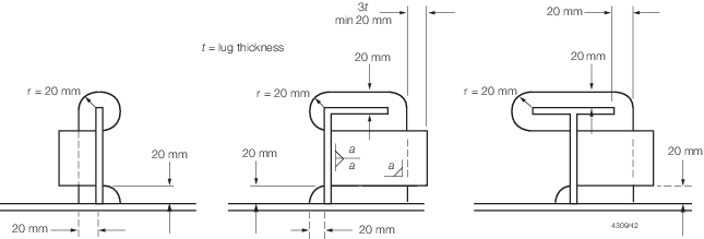
Figure 2.4.5 Typical lug connections
4.16.2 Lugs
or tripping brackets are to be fitted where shell longitudinals are
continuous through web frames in way of highly stressed areas of the
side shell (e.g. in way of fenders, etc).
4.16.3 Lugs
or tripping brackets are also to be fitted where continuous secondary
stiffeners are greater than half the depth of the primary stiffeners.
4.17 Insert plates
4.17.1 Where
thick insert plates are butt welded to thin plates, the edge of the
thick plate may require to be tapered. The slope of the taper is generally
not to exceed one in three.
4.17.2 The corners
of insert plates are to be suitably radiused.
4.18 Doubler plates
4.18.1 Doubler
plates are to be avoided in areas where corrosion may be a problem
and access for inspection and maintenance is limited.
4.18.2 Where
doubler plates are fitted, they are to have well radiused corners
and the perimeter is to be continuously welded. Large doubler plates
are also to be suitably slot welded, the details of which are to be
submitted for consideration.
4.19 Joint preparation
4.20 Construction tolerances
4.21 Riveting of light structure
4.21.1 Where
it is proposed to adopt riveted construction, full details of the
rivets or similar fastenings, including mechanical test results, are
to be indicated on the construction plans submitted for approval or
a separate riveting schedule is to be submitted.
4.21.2 Samples
may be required of typical riveted joints made by the Builder under
representative construction conditions and tested to destruction in
the presence of the Surveyor in shear, tension, compression or peel
at LR's discretion.
4.21.3 Where
riveting strength data sheets have been issued by a recognised Authority,
the values quoted in these sheets will normally be accepted for design
purposes.
4.21.4 Where
two dissimilar metals are to be joined by riveting, precautions are
to be taken to eliminate electrolytic corrosion to LR's satisfaction,
and where practicable, the arrangements should be such as to enable
the joint to be kept under observation at each survey without undue
removal of lining and other items.
4.21.5 Where
a sealing compound is used to obtain an airtight or watertight joint,
details are to be submitted of its proposed use and of any tests made
or experience gained in its use for similar applications.
4.21.6 Aluminium
alloy rivets in accordance with Ch 8, 2 Aluminium alloy rivets of
the Rules for Materials are to be used where practicable. However,
in the case of composite structures, including steel and GRP, consideration
will be given to the use of steel rivets. In such cases, the mating
surfaces are to be coated with a sealing paint.
4.21.7 Sealing
paints or compounds are not to be used with hot driven rivets.
4.22 Chemical bonding of structure
4.22.1 Where
chemical bonding of aluminium alloy of any load-bearing structure
is proposed, details of the materials and the processes to be used
are to be submitted for approval. These details are to include test
results of samples manufactured under LR survey under workshop conditions
to verify the strength, ageing effects and moisture resistance.
4.22.2 The adhesive
manufacturer's recommendations in respect of the specified jointing
system, comprising preparation of the surfaces to be adhered, the
adhesive, bonding and curing processes, are to be strictly followed
as variation of any step can severely affect the performance of the
joint.
4.22.3 Meticulous
preparation is essential where the joint is to be made by chemical
bonding. The method of producing bonded joints is to be documented
so that the process is repeatable after the procedure has been properly
established.
4.22.4 Bonded
joints are suitable for carrying shear loads, but are not in general
to be used in tension or where the load causes peeling or other forces
tending to open the joint. Loads are to be carried over as large an
area as possible.
4.22.5 Bonded
joints are to be suitably supported after assembly for the period
necessary to allow the optimum bond strength of the adhesive to be
to be developed. Entrained air pockets are to be avoided.
4.22.6 The use
of adhesives for main structural joints is not to be contemplated
unless considerable testing has established its validity, including
environmental testing and fatigue testing where considered necessary
by LR.
4.23 Triaxial stress considerations
4.23.1 Particular
care is to be taken to avoid triaxial stresses which may result from
poor joint design. Detailed joint design is of particular importance
in aluminium structures more so than many other materials. Some recommendations
in this respect are contained in LR's Guidance Notes for Structural
Details.
4.24 Butt straps
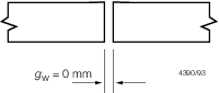
4.24.1 In general,
the scantling derivation of welded structures are to be determined
using the mechanical properties of the aluminium alloy in the welded
condition in accordance with Pt 7, Ch 2, 2.4 Mechanical properties for design.
However, where stiffeners are butt welded, special consideration will
be given to the use of suitable butt straps on the flanges which sufficiently
reinforce the area of the weld to allow the scantlings to be determined
using the unwelded mechanical properties. The butt weld is to be completed
and generally made flush with the flange of the stiffening member
before the butt strap is fitted and the butt strap weld is to be continuous.
Where this jointing method is proposed, the scantlings, arrangements
and locations of all joints and butt straps are to be submitted. Additionally,
LR may require mechanical tests to be carried out to demonstrate the
effectiveness of such arrangements.
4.25 Extruded `planking'
4.25.1 Joints
between adjacent extruded aluminium alloy planking, and the attachment
of the planking to the supporting structure is in general to be by
means of continuous welding.
4.25.2 The planking
is generally not to be included in the determination of the section
properties for both section modulus and inertia. However, special
consideration will be given to the inclusion of such materials on
the basis of the efficiency of the connection to the supporting structure.
4.26 Aluminium/steel transition joints
4.26.1 Provision
is made in this Section for explosion bonded composite aluminium/steel
transition joints used for connecting aluminium structures to steel
plating. Such joints are to be used in accordance with the manufacturer's
requirements, see also
Ch 8, 4 Aluminium/steel transition jointsof
the Rules for Materials.
4.26.2 Transition
joints are to be manufactured by an approved producer in accordance
with an approved specification which is to include the maximum temperature
allowable at the interface during welding.
4.26.5 Intermediate
layers between the aluminium and steel may be used, in which case
the material of any such layer is to be specified by the manufacturer
and is to be recorded in the approval certificate. Any such intermediate
layer is then to be used in all production transition joints.
4.26.6 Bimetallic
joints where exposed to seawater or used internally within wet spaces
are to be suitably protected to prevent galvanic corrosion.
4.27 Aluminium/wood connection
4.27.1 To minimise
corrosion of aluminium when in contact with wood in a damp or marine
environment the timber is to be primed and painted in accordance with
good practice. Alternatively the surface of the aluminium in contact
with the timber is to be coated with a substantial thickness of a
suitable sealant.
4.27.2 Timbers
such as western red cedar, oak and chestnut are not, unless well seasoned,
to be directly in contact with aluminium.
4.27.3 Timber
preservatives of the following types should be avoided: copper napthanate,
copper-chrome-arsenate, borax-boric acid.
|