
Section
8 Deck structures
8.1 General
8.1.1 The deck
plating is to be supported by transverse beams with fore and aft girders
or by longitudinals with deep transverse beams. The transverse and
deep transverse beams are to align with side main frames and side
web frames respectively.
8.1.2 Beams are
to be fitted at every frame and bracketed to the frames. Strong beams
and deep transverse beams are to align with and be effectively connected
to the side web frames. They are also to be fitted at the ends of
large openings in the deck.
8.1.3 The deck
plating and supporting structure are to be suitably reinforced in
way of cranes, masts, derrick posts and deck machinery.
8.1.4 Primary
stiffening members are to be continuous and substantially bracketed
at their end connections to maintain continuity of structural strength.
8.1.5 Secondary
stiffening members are to be effectively continuous and bracketed
at their end connections as appropriate.
8.1.7 The ends
of beams, longitudinals, girders and transverses are to be effectively
built into the adjacent structure, or equivalent arrangements provided.
8.1.8 Tripping
brackets are to be fitted on deep webs.
8.1.9 Deck structures
subject to concentrated loads, are to be suitably reinforced. Where
concentrations of loading on one side of a stiffening member may occur,
such as pillars out of line, the member is to be adequately stiffened
against torsion. Additional reinforcements may be required in way
of localised areas of high stress.
8.2 Strength/weather deck plating
8.2.3 It is recommended
that the working areas of the weather deck have an anti-slip surface.
8.2.4 Where decks
are sheathed with wood or other materials, details of the method of
attachment are to be submitted. See also
Pt 7, Ch 3, 2.4 Sheathing.
8.3 Lower deck/inside deckhouse plating
8.4 Accommodation deck plating
8.5 Cargo deck plating
8.6 Decks forming crowns of tanks
8.6.1 Decks forming
the crown of tanks are to comply with the requirements for the appropriate
deck, and are to be additionally examined for compliance with the
requirements for deep tank plating given in Pt 7, Ch 3, 7.4 Deep tank plating.
8.7 Strength/weather deck stiffening
8.7.1 The Rule
requirements for section modulus, inertia and web area for the strength/weather
deck primary stiffening are to be determined from the general
equations given in Pt 7, Ch 3, 1.17 Stiffening general, using
the design pressure heads from Pt 5, Ch 3, 3.1 Hull structures or Pt 5, Ch 4, 3.1 Hull structures for
non-displacement or displacement craft as appropriate, and the coefficients ΦZ, ΦI, and ΦA as detailed in Table 3.1.1 Section modulus, inertia and web
area coefficients for the load model (a).
8.7.2 The Rule
requirements for section modulus, inertia and web area for the strength/weather
deck secondary stiffening are to be determined from the general
equations given in Pt 7, Ch 3, 1.17 Stiffening general, using
the design pressure heads from Pt 5, Ch 3, 3.1 Hull structures or Pt 5, Ch 4, 3.1 Hull structures for
non-displacement or displacement craft as appropriate, and the coefficients ΦZ, ΦI, and ΦA as detailed in Table 3.1.1 Section modulus, inertia and web
area coefficients for the load model (b).
Special consideration will be given to the application of other load
models subject to the structural arrangement and degree of end fixity
provided.
8.7.3 Longitudinal
framing is, in general, to be adopted at the strength deck outside
line of openings, but special consideration will be given to proposals
for transverse framing.
8.8 Lower deck/inside deckhouse stiffening
8.8.1 The Rule
requirements for section modulus, inertia and web area for lower deck/inside
deckhouse stiffening are to be determined from the general equations
given in Pt 7, Ch 3, 1.17 Stiffening general using the design
pressure head from Pt 5, Ch 3, 3.1 Hull structures or Pt 5, Ch 4, 3.1 Hull structures for non-displacement or
displacement craft as appropriate and the coefficients ΦZ, ΦI, and ΦA as detailed in Table 3.1.1 Section modulus, inertia and web
area coefficients. Primary members are assumed
to be load model (a) and secondary members load model (b). However,
special consideration will be given to the application of other load
models subject to the structural arrangement and degree of end fixity
provided.
8.9 Accommodation deck stiffening
8.10 Cargo deck stiffening
8.10.1 The Rule
requirements for section modulus, inertia and web area for cargo deck
stiffening are to be determined from the general equations given in Pt 7, Ch 3, 1.17 Stiffening general using the design pressure head
from Pt 5, Ch 3, 3.1 Hull structures or Pt 5, Ch 4, 3.1 Hull structures for non-displacement or
displacement craft as appropriate and the coefficients Φ
Z, Φ
I, and Φ
A as
detailed in Table 3.1.1 Section modulus, inertia and web
area coefficients. Primary
members are assumed to be load model (a) and secondary members load
model (b). However, special consideration will be given to the application
of other load models subject to the structural arrangement and degree
of end fixity provided.
8.10.2 In addition,
where the cargo comprises wheeled vehicles, the requirements of Pt 7, Ch 5, 3 Vehicle decks are to be complied with.
8.11 Deck openings
8.11.1 All openings
are to be supported by an adequate framing system, pillars or cantilevers.
When cantilevers are used scantlings may be derived from direct calculations.
8.11.2 Where
stiffening members terminate in way of an opening they are to be attached
to carlings, girders, transverses or coaming plates.
8.11.3 The corners
of large hatchways in the strength/weather deck within 0,5L
R amidships are to be elliptical, parabolic or rounded, with
a radius generally not less than 1/24 of the breadth of the opening.
8.11.4 Where
elliptical corners are arranged, the major axis is to be fore and
aft, the ratio of the major to minor axis is to be not less than two
to one nor greater than 2,5 to one, and the minimum half-length of
the major axis is to be defined by  1 in Figure 3.8.1 Hatch opening geometry.
Where parabolic corners are arranged, the dimensions are also to be
as shown in Figure 3.8.1 Hatch opening geometry.
1 in Figure 3.8.1 Hatch opening geometry.
Where parabolic corners are arranged, the dimensions are also to be
as shown in Figure 3.8.1 Hatch opening geometry.

Figure 3.8.1 Hatch opening geometry
8.11.5 Where
the corners are parabolic or elliptical, insert plates are not required.
8.11.6 For other
shapes of corner, insert plates of the size and extent shown in Figure 3.8.2 Inserts in way of hatch openingwill, in general, be required.
The required thickness of the insert plate is to be not less than
25 per cent greater than the adjacent deck thickness, outside line
of openings.
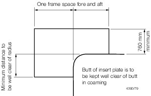
Figure 3.8.2 Inserts in way of hatch opening
8.11.7 For lower
decks the corners of large openings are to be rounded, with a radius
generally not less than 1/24 of the breadth of the opening.
8.11.8 Insert
plates will be required at lower decks in way of any rapid change
in hull form to compensate for loss of deck cross-sectional area.
Otherwise, insert plates will not normally be required.
8.11.9 Adequate
transverse strength is to be provided in the deck area between large
hatch openings, subjected to transverse and buckling loads.
8.12 Sheathing
8.13 Novel features
8.13.1 Where
large or novel hatch openings are proposed, detailed calculations
are to be submitted to demonstrate that the scantlings and arrangements
in way of the openings are adequate to maintain continuity of structural
strength.
|