
Section
8 Deck Structures
8.1 General
8.1.1 The deck
structure may be of either single skin or sandwich construction and
is to be supported by transverse beams with fore and aft girders or
by longitudinals with deep transverse beams.
8.1.2 Beams are
to be fitted at each frame position and be bracketed to the side frames.
Strong beams and deep transverse beams are to align with and be effectively
connected to the side web frames. They are also to be fitted at the
ends of large openings in the deck.
8.1.3 The ends
of beams, longitudinals, girders and transverses are to be effectively
built into the adjacent structure, or equivalent arrangements provided.
8.1.4 Primary
stiffening members are to be continuous and substantially bracketed
at their end connections to maintain continuity of structural strength.
8.1.5 Secondary
stiffening members are to be effectively continuous and bracketed
at their end connections as appropriate.
8.1.6 Deck structures
subject to concentrated loads, such as pillars out of line, are to
be suitably reinforced. Where concentrations of loading on one side
of a stiffener may occur, the stiffener is to be adequately stiffened
against torsion. Additional reinforcements may be required in way
of localised areas of high stress.
8.1.8 Tripping
brackets are to be fitted on deep webs.
8.2 Symbols and definitions
8.3 Strength/weather deck laminate
8.3.1 The bending
moment assumed to be carried by the strength/weather deck plating
is to be not less than that determined from Pt 8, Ch 3, 1.9 Plate and sandwich laminates 1.9.1, using the design pressure from Pt 5, Ch 3, 3.1 Hull structures or Pt 5, Ch 4, 3.1 Hull structures for
non-displacement or displacement type craft as appropriate. This bending
moment is to be applied to laminates of both single skin and sandwich
construction in the determination of the panel scantling required
by Pt 8, Ch 3, 8.3 Strength/weather deck laminate 8.3.2 and Pt 8, Ch 3, 8.3 Strength/weather deck laminate 8.3.4 respectively.
8.3.3 In no case
is the minimum thickness of single skin plating to be taken as less
than 4 mm.
8.3.6 Special
consideration may be given to laminate thicknesses lesser than that
required by Pt 8, Ch 3, 8.3 Strength/weather deck laminate 8.3.3 and Pt 8, Ch 3, 8.3 Strength/weather deck laminate 8.3.5, provided that all of the structural
strength requirements of the Rules are complied with, a satisfactory
water barrier is provided, see
Pt 8, Ch 3, 2.3 Sandwich skin laminate 2.3.1, and the equivalent impact resistance is demonstrated
as required by Pt 8, Ch 3, 2.8 Impact considerations 2.8.2.
8.3.8 It is recommended
that working areas of the weather deck have an anti-slip surface.
8.3.9 Where decks
are sheathed with wood or other materials, details of the method of
attachment are to be submitted, see also
Pt 8, Ch 3, 2.9 Sheathing.
8.4 Lower deck/inside deckhouse deck laminate
8.4.1 The bending
moment assumed to be carried by the lower deck/inside deckhouse deck
plating is to be not less than that determined from Pt 8, Ch 3, 1.9 Plate and sandwich laminates 1.9.1, using the design pressure from Pt 5, Ch 3, 3.1 Hull structures or Pt 5, Ch 4, 3.1 Hull structures for non-displacement or
displacement type craft as appropriate. This bending moment is to
be applied to laminates of both single skin and sandwich construction
in the determination of the panel scantling required by Pt 8, Ch 3, 8.4 Lower deck/inside deckhouse deck laminate 8.4.2 and Pt 8, Ch 3, 8.4 Lower deck/inside deckhouse deck laminate 8.4.4 respectively.
8.4.3 In no case
is the minimum thickness of single skin plating to be taken as less
than 3 mm.
8.5 Accommodation deck laminate
8.5.2 Sandwich
timber, plywood or other forms of deck construction will be considered
on the basis of equivalent strength and stiffness.
8.6 Cargo deck laminate
8.6.1 The bending
moment assumed to be carried by the cargo deck plating is to be not
less than that determined from Pt 8, Ch 3, 1.9 Plate and sandwich laminates 1.9.1,
using the design pressure from Pt 5, Ch 3, 3.1 Hull structures or Pt 5, Ch 4, 3.1 Hull structures for
non-displacement or displacement type craft as appropriate. This bending
moment is to be applied to laminates of both single skin and sandwich
construction in the determination of the panel scantling required
by Pt 8, Ch 3, 8.6 Cargo deck laminate 8.6.2 and Pt 8, Ch 3, 8.6 Cargo deck laminate 8.6.4 respectively.
8.6.3 In no case
is the minimum thickness of single skin plating to be taken as less
than 4 mm.
8.6.6 Special
consideration may be given to laminate thicknesses lesser than that
required by Pt 8, Ch 3, 8.6 Cargo deck laminate 8.6.3 and Pt 8, Ch 3, 8.6 Cargo deck laminate 8.6.5, provided that all of the structural
strength requirements of the Rules are complied with, a satisfactory
water barrier is provided, see
Pt 8, Ch 3, 2.3 Sandwich skin laminate 2.3.1, and the equivalent impact resistance is demonstrated
as required by Pt 8, Ch 3, 2.8 Impact considerations 2.8.2.
8.7 Decks forming crown of tanks
8.7.1 Decks forming
the crowns of tanks are to comply with the requirements for the appropriate
deck, and are to be additionally examined for compliance with the
requirements for deep tanks given in Pt 8, Ch 3, 7.4 Deep tanks.
8.8 Strength/weather deck stiffening
8.8.1 The Rule
requirements for bending moment, shear force, shear stress and deflection
for the strength/weather deck primary stiffeners are
to be determined from the general equations given in Pt 8, Ch 3, 1.15 Stiffeners general, using the design pressure from Pt 5, Ch 3, 3.1 Hull structures or Pt 5, Ch 4, 3.1 Hull structures for non-displacement or
displacement type craft as appropriate, and the coefficients ΦM, ΦS and Φδ as indicated in Table 3.1.10 Shear force, bending moment and
deflection coefficients for the load model (a).
8.8.2 The Rule
requirements for bending moment, shear force, shear stress and deflection
for the strength/weather deck secondary stiffeners are
to be determined from the general equations given in Pt 8, Ch 3, 1.15 Stiffeners general, using the design pressure from Pt 5, Ch 3, 3.1 Hull structures or Pt 5, Ch 4, 3.1 Hull structures for non-displacement or
displacement type craft as appropriate, and the coefficients ΦM, ΦS and Φδ as indicated in Table 3.1.10 Shear force, bending moment and
deflection coefficients for the load model (b).
Special consideration will be given to the application of other load
models subject to the structural arrangement and degree of end fixity
provided.
8.9 Lower deck/inside deckhouse stiffening
8.9.1 The Rule
requirements for bending moment, shear force, shear stress and deflection
for the lower deck/inside deckhouse stiffeners are to be determined
from the general equations given in Pt 8, Ch 3, 1.15 Stiffeners general,
using the design pressure from Pt 5, Ch 3, 3.1 Hull structures or Pt 5, Ch 4, 3.1 Hull structures for
non-displacement or displacement type craft as appropriate, and the
coefficients ΦM, ΦS and Φδ as
indicated in Table 3.1.10 Shear force, bending moment and
deflection coefficients for
the appropriate load model. Primary members are assumed to be load
model (a), secondary members are, in general, assumed to load model
(b), however special consideration will be given to the application
of other load models subject to the structural arrangement and degree
of end fixity provided.
8.10 Accommodation deck stiffening
8.11 Cargo decks
8.11.1 The Rule
requirements for bending moment, shear force, shear stress and deflection
for cargo deck stiffeners are to be determined from the general equations
given in Pt 8, Ch 3, 1.15 Stiffeners general, using the design
pressure from Pt 5, Ch 3, 3.1 Hull structures or Pt 5, Ch 4, 3.1 Hull structures for non-displacement or
displacement type craft as appropriate, and the coefficients ΦM, ΦS and Φδ as indicated in Table 3.1.10 Shear force, bending moment and
deflection coefficients for the appropriate load
model. Primary members are assumed to be load model (a), secondary
members are, in general, assumed to be load model (b), however special
consideration will be given to the application of other load models
subject to the structural arrangement and degree of end fixity provided.
Additionally where the cargo comprises wheeled vehicles the requirements
of Pt 8, Ch 5, 3 Vehicle decks are to be complied with.
8.12 Deck openings
8.12.1 All openings
are to be supported by an adequate framing system, pillars or cantilevers.
When cantilevers are used, stiffening requirements may be derived
from direct calculations.
8.12.2 Where
stiffening members are stopped in way of an opening, they are to be
attached to carlings, girders, transverses or coamings.
8.12.3 The corners
of large hatchways in the strength/weather deck within 0,5L amidships
are to be elliptical, parabolic or rounded, with a radius generally
not less than 1/24 of the breadth of the opening.
8.12.4 Where
elliptical corners are arranged, the major axis is to be fore and
aft, the ratio of the major to minor axis is to be not less than two
to one, nor greater than 2,5 to 1, and the minimum half-length of
the major axis is to be defined by l
1 in Figure 3.8.1 Hatch opening geometry. Where parabolic corners
are arranged, the dimensions are also to be as shown in Figure 3.8.1 Hatch opening geometry.
8.12.5 Where
the corners are parabolic or elliptical, increased thickness of laminate
will, in general, not be required.
8.12.6 For other
shapes of corner, reinforcement of the size and extent shown in Figure 3.8.2 Reinforcement in way of hatch opening will, in general, be required.
The required weight of reinforcement is to be not less than 25 per
cent greater than the adjacent deck laminate.
8.12.7 For lower
decks the corners of large openings are to be rounded, with a radius
generally not less than 1/24 of the breadth of the opening.

Figure 3.8.1 Hatch opening geometry
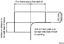
Figure 3.8.2 Reinforcement in way of hatch opening
8.12.8 Reinforcement
as given in Pt 8, Ch 3, 8.12 Deck openings 8.12.6 will be required
at lower decks in way of rapid change in hull form to compensate for
loss of deck cross-sectional area. Otherwise, reinforcement will not
normally be required.
8.12.9 Adequate
transverse strength is to be provided in the deck area between large
hatch openings and subjected to transverse and buckling loads.
8.13 Sheathing
8.14 Novel features
8.14.2 Where
large or novel hatch openings are proposed, detailed calculations
are to be submitted to demonstrate that the scantlings and arrangements
in way of the openings are adequate to maintain continuity of structural
strength.
|