
Section
3 Load cases
3.1 General
3.1.1 The
standard load cases, given in Table 2.3.1 Load combinations, are to be considered. The purpose of these load cases
is to ensure that the longitudinal, transverse and shear strength
of the hull structure complies with the acceptance criteria given
in Vol 4, Pt 1, Ch 2, 5 Acceptance criteria.
Table 2.3.1 Load combinations
| Wave direction
|
Load cases
|
Load components (see Note 1)
|
|
|
|
A. M
swh
|
B. M
sws
|
C. M
wh
|
D. M
ws
|
E. M
h
|
F. M
sph
|
G. M
sps
|
H. M
lt
|
I. M
tt
|
J. θmax
|
|
|
(1)
|
1,0
|
—
|
1,0
|
—
|
—
|
0,3
|
—
|
—
|
–0,2
|
—
|
| Head
Seas
|
(2)
|
—
|
1,0
|
—
|
1,0
|
—
|
—
|
0,3
|
—
|
–0,2
|
—
|
|
|
(3)
|
1,0
|
—
|
0,1
|
—
|
—
|
1,0
|
—
|
0,2
|
—
|
—
|
| Beam
Seas
|
(4)
|
—
|
1,0
|
—
|
0,1
|
—
|
—
|
1,0
|
0,2
|
—
|
—
|
| Oblique Seas
|
(5)
|
(see Note 2)
|
—
|
—
|
–0,3
|
0,4
|
—
|
1,0
|
0,3
|
—
|
|
|
(6)
|
(see Note 2)
|
—
|
—
|
1,0
|
0,4
|
—
|
—
|
0.2
|
—
|
|
|
(7)
|
1,0
|
—
|
—
|
0,2
|
–0,2
|
0,6
|
—
|
—
|
1,0
|
—
|
|
|
(8)
|
—
|
1,0
|
—
|
—
|
—
|
—
|
—
|
—
|
—
|
1,0
|
Note
1. For each load case the load components
give the proportion of the Rule moments to be applied. All moments
should be positive.
Note
2. The still water bending moment to be
used is that which results in the highest stress for the load case
under consideration.
|
3.2 Load cases – Global model
3.2.1 The
load cases, 1–8, as described in Table 2.3.1 Load combinations, are to be comprised of the proportion of global load
components as indicated. In each load case, one of the load components
is maximised. The load components may be combined by superposition.
3.3 Load cases – Local model
3.3.1 In general,
all load cases specified in Table 2.3.1 Load combinations are to be investigated to identify areas that require
local fine mesh analysis.
3.3.2 The
fine mesh analysis can be carried out by means of separate local finite
element models, in conjunction with the boundary conditions obtained
from the global coarse mesh model. Alternatively, fine mesh zones
may be incorporated into the global coarse mesh model.
3.3.3 Where
appropriate, secondary loads such as pressure loads are to be applied
in conjunction with the boundary displacements obtained from the global
model.
3.4 Component A – Still water loads, hog - Component B –
Still water loads, sag
3.4.1 The
still water loads are to be applied to the global finite element model
regardless of whether Rule loads are being applied or loads calculated
by direct calculation.
3.4.2 Hog
and sag still water load cases are to be analysed fulfilling the following
criteria:
-
Ship upright and
at or near to the maximum draught.
-
The still water
bending moment cases are to approximate, as far as is possible, the
assigned, or specified, permissible still water bending moment condition
distributions. It may only be necessary to include one loading condition;
if there is not a large variation in the deadweight distribution.
3.4.3 The
following still water loads are to be included:
-
Self weight –
as generated from the modelled hull structure, suitably factored to
achieve the specified steel weight, including the position of the
LCG. In this respect, it may be useful to divide the model longitudinally
into a number of material zones, each of which can have a separate
factored value for the steel density.
-
Machinery,
outfit and other equipment – all major items to be applied
as point loads or pressure loads at the correct locations. Minor or
unknown items may be included in the steel weight.
-
Buoyancy
loads – to be applied as pressure loads , ρgh,
on wetted shell elements, where h is the distance of
the element centroid below the still waterline.
-
Ballast
and fuel oil – to be applied as pressure loads on tank
boundaries, based on the actual liquid head and density.
-
Containers –
vertical point loads to be applied at each corner of the stack base,
whether above or below deck.
-
Cargo, payload,
passengers or vehicles – as point loads, uniformly distributed
loads or pressure loads at the correct locations.
3.5 Component C – Vertical wave bending moment, hog - Component
D – Vertical wave bending moment, sag
3.5.1 The
vertical wave bending moment load cases are to be applied by using
a static wave balance program. Separate cases are required for the
hog and sag conditions. Each case is comprised of a wave with the
following properties:
-
A wavelength equal
to LBP
-
A wave crest amidships
for the hogging condition and a wave trough amidships for the sagging
condition
-
A sinusoidal wave
profile
-
A wave height
sufficient to induce the Rule hogging or sagging design vertical wave
bending moment (VWBM) amidships, as given in Vol 1, Pt 5, Ch 4, 2.4 Vertical wave bending moment.
3.5.2 The
wave height required to induce the required bending moment will need
to be derived by trial and error using a suitable longitudinal strength
program. The ship is to be balanced on the wave and the resulting
draught, trim and wave parameters are to be used for determination
of external pressure distribution. This wave is to be determined for
both the hog and sag condition.
3.5.3 The
pressure values to be applied should not include the pressure component
or buoyancy loads due to the still water condition.
3.6 Component E – Horizontal wave bending moment
3.6.1 The
Rule horizontal bending moment distribution, as described in Figure 2.3.1 Horizontal wave moment distribution, is to be modelled by
applying longitudinal force pairs at each transverse bulkhead position
in the plane of the side shell. These loads are to be distributed
longitudinally along the depth of the side hull structure or of the
centre hull structure at the forward and aft ends where the side hull
structure has terminated. When integrated along the ship length, the
incremental moment couples are to generate the Rule horizontal wave
bending moment distribution specified in Vol 1, Pt 5, Ch 4, 2.6 Horizontal bending moment.
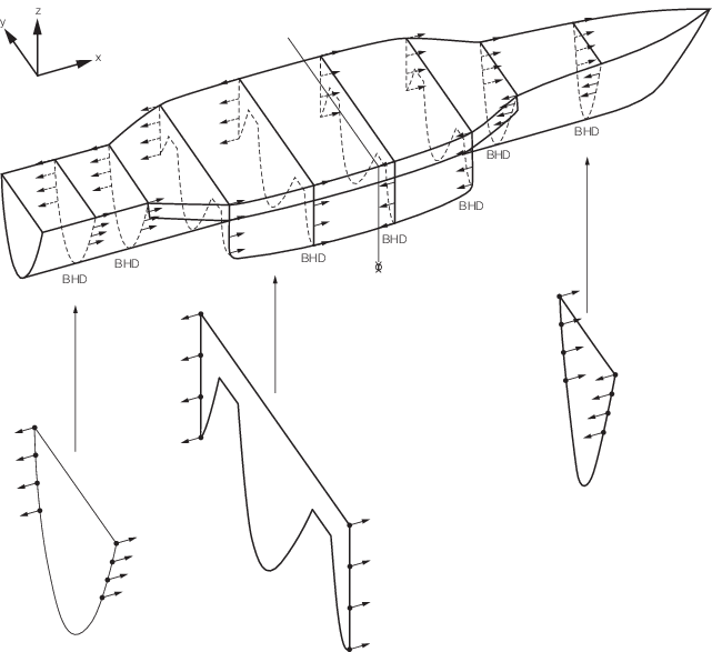
Figure 2.3.1 Horizontal wave moment distribution
3.7 Component F – Splitting moment, hog - Component G –
Splitting moment sag
3.7.1 The
splitting moment occurs when the waves force the side hulls away from
(sag) or towards (hog) the centre hull, resulting in stresses in the
cross-deck structure.
3.7.2 The
splitting moment may be achieved by applying simplified line loads,
in the directions depicted in Figure 2.3.2 Splitting moment, hog for hog and Figure 2.3.3 Splitting moment, sag for
sag, at the following locations:
-
A line load is
to be applied vertically on the length of the keel of each of the
side hulls.
-
A line load is
also to be applied transversely, near the keel in way of supporting
structure, along the length of the outboard side of both side hulls.
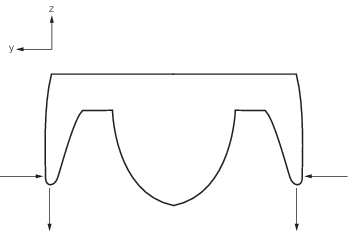
Figure 2.3.2 Splitting moment, hog
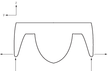
Figure 2.3.3 Splitting moment, sag
3.7.3 The
magnitude of the distributed loads should be determined so that the
resulting splitting moment distribution along the cross-deck is equal
to that specified in Vol 1, Pt 5, Ch 4, 3.1 Splitting moment.
3.7.4 Alternatively,
uniformly distributed loads may be applied to the side hulls in order
to achieve the Rule splitting moment distribution. In the sag case,
these loads would act on the inside of the side hulls and in the case
of the hog would act on the outside of the side hulls. The loads would
consist of a hydrostatic head, as well as a dynamic component sufficient
to generate the Rule splitting moment value.
3.8 Component H – Longitudinal torsional moment
3.8.2 The
moment is to be applied as a distributed force couple on all nodes
in the 'vertical' portion of the bulkhead where it intercepts the
side shell.
3.8.3 The
torsional moment, T, required at each bulkhead position
can be calculated from:
where
|
M
Tf
|
= |
is the Rule torsional moment value midway between the bulkhead
under consideration and the next bulkhead forward |
|
M
Ta
|
= |
is the Rule torsional moment value mid-way between the bulkhead
under consideration and the next bulkhead aft. |
3.8.4 Other
proposed methods of modelling the Rule hydrodynamic torque distribution
will be specially considered.
3.9 Component I – Transverse torsional moment
3.10 Component J – Maximum roll
3.10.1 A
static roll angle of 30° is to be applied to the model. The draft
and trim are to be adjusted in order to balance the hydrostatic loads
and the displacement. Still water loads are to be included in this
load case. All loads subject to gravity are to be resolved into their
correct components given the heeled position of the ship.
|