
Section
7 Welding and structural details
7.1 Application
7.1.1 Requirements are given in this Section for the following:
- Welding-connection details, defined practices and sequence,
consumables and equipment, procedures, workmanship and inspection.
- End connection scantlings and constructional details for
longitudinals, beams, frames and bulkhead stiffeners.
- Primary member proportions, stiffening and construction
details.
7.2 Welding – general
7.2.1 The plans to be submitted for approval are to indicate clearly details of the welded
connections of main structural members, including the type and size of welds. This
requirement includes welded connections to steel castings. The information to be
submitted should include the following:
- Whether weld sizes given are throat thicknesses or leg
lengths.
- Grades and thicknesses of materials to be welded.
- Location, types of joints and angles of abutting
members.
- Reference to welding procedures to be used.
- Sequence of welding of assemblies and joining up of
assemblies.
7.3 Welding – fillet welds
7.3.2 Where double continuous fillet welding is proposed, the throat thickness is to be
determined taking  equal to 1,0. equal to 1,0.
7.3.3 The leg length of the weld is to be not less  than times the specified throat thickness. than times the specified throat thickness.
7.3.4 The plate thickness, tp, to be used in the above calculation is
generally to be that of the thinner of the two parts being joined. Where the
difference in thickness is considerable, the size of fillet will be considered.
7.3.5 Where the thickness of the abutting member of the connection (e.g. the web of a
stiffener) is greater than 15 mm and exceeds the thickness of the table member (e.g.
plating), the welding is to be double continuous and the throat thickness of the
weld is to be not less than the greatest of the following:
- 0,21 times thickness of the table member. The table
member thickness used need not exceed 25 mm.
- 0,21 (0,27 in tanks) times half the thickness of the
abutting member.
- As required by Table 4.7.2 Throat thickness
limits.
7.3.7 Double continuous fillet welding is to be adopted in the following locations, and may
be used elsewhere if desired:
- Boundaries of weathertight decks and erections,
including hatch coamings, companionways and other openings.
- Boundaries of tanks and watertight compartments.
- All lap welds in tanks.
- Primary and secondary members to plating in way of end
connections, and end brackets to plating in the case of lap connections.
- Where Pt 3, Ch 4, 7.3 Welding – fillet welds 7.3.5
applies.
- All water ballast tanks.
- Other connections or attachments, where considered
necessary, and in particular the attachment of minor fittings to higher
tensile steel plating.
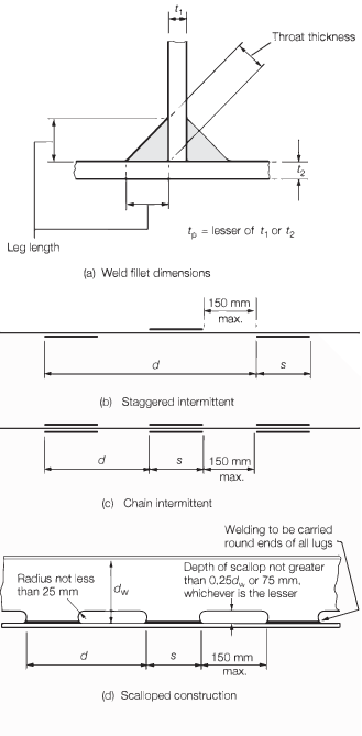
Figure 4.7.1 Weld dimensions and types
7.3.8 Where intermittent welding is used, the welding is to be made double continuous in
way of brackets, lugs and scallops and at the orthogonal connections with other
members.
7.3.9 As an alternative to intermittent welding, single-sided welding may be used. Only
mechanised single-sided welding is acceptable although manual single-sided welding
may be used at non-critical locations, e.g. deck house stiffeners. Where
single-sided welding is used, the welding is to be made double continuous in way of
brackets, lugs and scallops and at the orthogonal connections with other members.
7.3.10 Where structural members pass through the boundary of a tank, and leakage into the
adjacent space could be hazardous or undesirable, full penetration welding is to be
adopted for the members for at least 150 mm on each side of the boundary.
Alternatively, a small scallop of suitable shape may be cut in the member close to
the boundary outside the compartment, and carefully welded all round.
Table 4.7.1 Weld factors
| Item
|
Weld factor
|
Remarks
|
| (1)
|
General
application:
|
|
except as required below:
|
|
|
Watertight
plate boundaries
|
0,34
|
|
|
|
Non-tight
plate boundaries
|
0,13
|
|
|
|
Longitudinals,
frames, beams and other secondary members to shell, deck or bulkhead
plating
|
0,10
|
|
|
|
|
0,13
|
in tanks
|
|
|
|
0,21
|
in way of end connections
|
|
|
Panel
stiffeners, etc.
|
0,10
|
|
|
|
Overlap welds
generally
|
0,27
|
|
|
|
Longitudinals
of the flat-bar type to plating
|
|
see Note 2
|
| (2)
|
Bottom
construction in way of tanks:
|
|
|
|
|
Non-tight centre girder:
|
to keel
|
0,27
|
|
|
|
|
to bottom
|
0,21
|
no scallops
|
|
|
|
|
0,21
|
in way of 0,2 times span at ends
|
|
|
Non-tight
boundaries of floors, girders and brackets
|
0,27
|
in way of brackets at lower end of main
frame
|
|
|
Watertight bottom girders
|
|
0,34
|
|
|
|
Connection of
girder to inner bottom in way of longitudinal bulkheads supported on
inner bottom
|
0,44
|
|
|
|
Connection of
floors to inner bottom in way of plane bulkheads, bulkhead stools or
corrugated and double plate bulkheads supported on inner bottom. The
supporting floors are to be continuously welded to the inner
bottom
|
0,44
|
Weld material compatible with floor
material
|
| (3)
|
Hull framing:
|
|
|
|
|
|
Webs of web frames:
|
to shell
|
0,16
|
|
|
|
|
to face plate
|
0,13
|
|
|
|
Tank side
brackets to shell and inner bottom
|
0,34
|
|
| (4)
|
Decks and supporting structure:
|
|
|
|
|
|
Strength deck plating to shell
|
|
|
As shown in Table 4.7.5 Weld connection
of strength deck plating to sheerstrake but alternative
proposals will be considered
|
|
|
Webs of
cantilevers to deck and to shell in way of root bracket
|
0,44
|
|
|
|
Webs of cantilevers to face plate
|
|
0,21
|
|
|
|
Pillars:
|
fabricated
|
0,10
|
|
|
|
|
end connections
|
0,34
|
see Note 1
|
|
|
|
end connections (tubular)
|
full penetration
|
|
|
|
Girder web
connections and brackets in way of pillar heads and heels
|
|
continuous
|
| (5)
|
Bulkheads and
tank construction:
|
|
|
|
|
Plane, double
plate and corrugated watertight bulkhead boundary at bottom, bilge,
inner bottom, deck and connection to shelf plate, where
fitted
|
0,44
|
weld size to be based on
thickness of bulkhead plating
weld material to be
compatible with bulkhead plating material
|
|
|
Shelf plate connection to stool
|
|
0,44
|
weld size to be based on
thickness of bulkhead plating
weld material to be
compatible with bulkhead plating material
|
|
|
Plane, double
plate and corrugated bulkhead boundaries in way of deep
tanks:
|
|
|
|
|
- Boundary at
bottom, bilge, inner bottom and deck
|
0,44
|
|
|
|
- Connection
of stool and bulkhead to lower stool shelf plating
|
full penetration
|
|
|
|
- Connection
of stool and bulkhead plating to upper stool shelf plate
|
0,44
|
|
|
|
- Connection
of bulkhead plating to hopper and topside tanks
|
0,44
|
|
|
|
- Connection
of bulkhead plating to side shell
|
0,34
|
|
|
|
Secondary
members where acting as pillars
|
0,13
|
|
|
|
Non-watertight
pillar bulkhead boundaries
|
0,13
|
|
|
|
Perforated
flats and wash bulkhead boundaries
|
0,10
|
|
| (6)
|
Structure in
pump room:
|
|
|
|
|
Centre girder
to keel and inner bottom
|
0,27
|
|
|
|
Floors to
centre girder in way of machinery seating
|
0,27
|
|
|
|
Floors and
girders to shell and inner bottom
|
0,21
|
|
|
|
Machinery
seating to supporting structure
|
0,21
|
|
|
|
Transverse and longitudinal framing to shell
|
0,13
|
|
| (7)
|
Miscellaneous
fittings and equipment:
|
|
|
|
|
Rings for
manhole type covers, to deck or bulkhead
|
0,34
|
|
|
|
Primary and
secondary stiffening of tank covers
|
0,13
|
|
|
|
Ventilator,
air pipe, etc. coamings to deck and fittings
|
0,21
|
|
|
|
Scuppers and discharges, to deck
|
|
0,44
|
|
|
|
Deck machinery seats to deck
|
|
0,21
|
generally
|
|
|
Mooring equipment seats
|
|
0,21
|
generally, but increased or full
penetration welding may be required
|
|
|
Guard rails, stanchions, etc. to
deck
|
|
0,34
|
|
|
Note 1. Where pillars are fitted inside tanks or under watertight
flats, the end connection is to be such that the tensile stress
in the weld does not exceed 108 N/mm2.
Note 2. The throat
thickness of the weld is to be determined by Pt 3, Ch 4, 7.3 Welding – fillet welds 7.3.5. For longitudinals within D/4 of the strength
deck and with a thickness less than 100 mm, the throat thickness
need not exceed 5,5 mm.
|
7.4 Welding of primary structure
7.4.2 The weld connection to shell, deck or bulkhead is to take account of the material
lost in the notch where longitudinals or stiffeners pass through the member. Where
the width of notch exceeds 15 per cent of the stiffener spacing, the weld factor is
to be multiplied by:
7.4.3 Where direct calculation procedures have been adopted, the weld factors for the 0,2 x
overall length at the ends of the members will be considered in relation to the
calculated loads.
7.4.4 The throat thickness limits given in Table 4.7.2 Throat thickness
limits are
to be complied with.
Table 4.7.2 Throat thickness
limits
| Item
|
Throat thickness, in mm
|
|
|
Minimum
|
Maximum
|
| (1)
|
Double continuous
welding
|
0,21tp
|
0,44tp
|
| (2)
|
Intermittent welding
|
0,27tp
|
0,44tp or 4,5
|
| (3)
|
All welds, overriding
minimum
|
|
|
| (a)
|
Plate thickness
tp ≤ 7,5 mm
|
|
|
|
|
Hand or automatic
welding
|
3,0
|
-
|
|
|
Automatic deep penetration
welding
|
3,0
|
-
|
| (b)
|
Plate thickness
tp > 7,5 mm
|
|
|
|
|
Hand or automatic
welding
|
3,25
|
-
|
|
|
Automatic deep penetration
welding
|
3,0
|
-
|
|
Note 1. In all
cases, the limiting value is to be taken as the greatest of the
applicable values given above.
Note 2. Where
tp exceeds 25 mm, the limiting values can
be calculated using a notional thickness equal to
0,4(tp + 25) mm, but is not to be taken as
less than 25 mm.
Note 3. The maximum
throat thicknesses shown are intended only as a design limit for
the approval of fillet welded joints. Any welding in excess of
these limits is to be to the Surveyor's satisfaction.
|
Table 4.7.3 Connections of primary structure
| Primary member face area, in cm2
|
|
Weld factor
|
| Exceeding
|
Not
exceeding
|
Position
see Note 1
|
In
tanks
|
|
In dry
spaces
|
|
|
|
|
|
To face
plate
|
To
plating
|
To face
plate
|
To
plating
|
|
|
30,0
|
At ends
|
0,21
|
0,27
|
0,21
|
0,21
|
|
|
|
Remainder
|
0,10
|
0,16
|
0,10
|
0,13
|
| 30,0
|
65,0
|
At ends
|
0,21
|
0,34
|
0,21
|
0,21
|
|
|
|
Remainder
|
0,13
|
0,27
|
0,13
|
0,16
|
| 65,0
|
95,0
|
At ends
|
0,34
|
0,44
see Note 2
|
0,21
|
0,27
|
|
|
|
Remainder
|
0,27
|
0,34
|
0,16
|
0,21
|
| 95,0
|
130,0
|
At
ends
|
0,34
|
0,44
see Note 2
|
0,27
|
0,34
|
|
|
|
Remainder
|
0,27
|
0,34
|
0,21
|
0,27
|
| 130,0
|
|
At ends
|
0,44
|
0,44
see Note 2
|
0,34
|
0,44
see Note 2
|
|
|
|
Remainder
|
0,34
|
0,34
|
0,27
|
0,34
|
|
Note 1. The weld factors ‘at ends' are to be applied for 0,2 times
the overall length of the member from each end, but at least
beyond the toes of the member end brackets. On vertical webs the
increased welding may be omitted at the top but is to extend at
least 0,3 times the overall length from the bottom.
Note 2. Where the web plate thickness is increased locally, the
weld size may be based on the thickness clear of the increase
but is to be not less than 0,34 times the increased
thickness.
|
Table 4.7.4 Secondary member end connection welds
| Connection
|
Weld area, Aw, in cm2
|
Weld factor
|
| (1) Stiffener welded direct to
plating
|
0,25As or 6,5
cm2 whichever is the greater
|
0,34
|
| (2) Bracketless connection of stiffeners or
stiffener lapped to bracket or bracket lapped to stiffener:
|
|
0,27
|
| (a) In dry space
|

|
0,34
|
| (b) In tank
|

|
0,34
|
| (3) Bracket welded to face of stiffener and
bracket connection to plating
|
-
|
0,34
|
| (4) Stiffener to plating for 0,1 times span
at ends, or in way of end bracket if that be greater
|
-
|
0,34
|
| Symbols
|
|
As |
= |
cross-sectional area of the stiffener, in cm2
|
|
Aw |
= |
the area of the weld, in cm2, and is
calculated as total length of weld, in cm, times throat
thickness, in cm |
|
Z |
= |
the section modulus, in cm2, of
the stiffener on which the scantlings of the bracket are
based, see
Pt 3, Ch 4, 7.8 Secondary member end connections
|
|
|
|
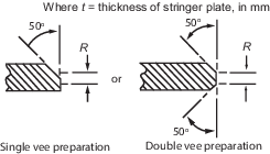
Table 4.7.5 Weld connection of strength deck plating to sheerstrake
| Item
|
Deck stringer plate thickness, mm
|
Weld type
|
| 1
|
t ≤ 15
|
Double continuous fillet weld with a weld
factor of 0,44
|
| 2
|
15 < t ≤ 20
|
Single vee preparation to provide included
angle of 50° with root  in conjunction with a continuous
fillet weld having a weld factor of 0,39; or in conjunction with a continuous
fillet weld having a weld factor of 0,39; or
Double vee
preparation to provide included angles of 50° with root 
|
| 3
|
t > 20
|
Double vee preparation to provide included
angles of 50° with root  but not to exceed 10 mm but not to exceed 10 mm
|
|
|
Note 1. Welding procedure, including joint preparation, is to be
specified. Procedure is to be qualified and approved for
individual Builders.
Note 3. For thickness t in excess of 20 mm the deck stringer
plate can be bevelled to achieve a reduced thickness at the weld
connection. The length of the bevel is in general to be based on
a taper not exceeding 1 in 3 and the reduced thickness is in
general to be not less than 0,65 times the thickness of the deck
stringer plate or 20 mm, whichever is the greater.
Note 4. Alternative connections will be considered.
|
7.5 Welding of primary and secondary end connections
7.5.1 Welding of end connections of primary members is to be such that the area of welding
is not less than the cross-sectional area of the member, and the weld factor is to
be not less than 0,34 in tanks or 0,27 elsewhere.
7.5.3 The area of weld, Aw, is to be applied to each arm of the bracket
or lapped connection.
7.5.4 Where a longitudinal strength member is cut at a primary support and the continuity
of strength is provided by brackets, the area of weld is to be not less than the
cross-sectional area of the member.
7.6 Welding equipment, consumables and procedure
7.6.6 A sufficient number of skilled supervisors is to be provided to ensure an effective
and systematic control at all stages of welding operations.
7.7 Inspection of welds
7.7.1 Effective arrangements are to be provided by the Shipbuilder for the inspection of
finished welds to ensure that all welding has been satisfactorily completed.
7.7.5 Checkpoints are not to be identified on the ship’s structural components prior to the
welding taking place.
7.7.6 For ultrasonic examination the length of each checkpoint is to be 0,5 m and for
radiographic examination the length is to be a minimum of 0,3 m. At weld
intersections, examination is to be in both weld directions.
7.7.7 The Builder is to provide the Surveyor with all the NDE reports of the checkpoints.
These reports are to be available for the Surveyor to review within a short time
after inspection, normally considered to be within 10 working days of the
examination being carried out. Where welds are repaired, the NDE report is to
include details of examination of both the defective weld and of the re-weld.
7.7.8 Where the Surveyor notes that a checkpoint has been repaired without
record of the original defect, the Shipyard is to carry out additional examinations
on additional lengths of weld. These lengths are to be adjacent to and on both sides
of the defective checkpoint. These additional examinations are to be carried out in
the presence of the Surveyor and reported in accordance with Pt 3, Ch 4, 7.7 Inspection of welds 7.7.7.
7.7.9 Where checkpoints are found to contain continuous or semi-continuous
defects, additional lengths of weld adjacent to and on both sides of the defective
length are to be subject to further volumetric examination. The NDE reports are to
be submitted in accordance with Pt 3, Ch 4, 7.7 Inspection of welds 7.7.7.
Table 4.7.6 Checkpoint locations
| Item
|
Location
|
Checkpoints
|
| Intersections of butts and seams of fabrication and
section welds
|
Throughout
|
|
| (a) hull envelope, shell envelope and deck structure
plating:
|
|
- at highly stressed areas, see
Note 1
- remainder
|
all
|
| 1 in 2
|
| (b) longitudinal and transverse bulkheads
|
1 in 2
|
| (c) inner bottom plating:
|
1 in
2
|
| Butt welds in plating
|
Throughout
|
1 m in 25 m,
see Notes 2 and 3
|
| Seam welds in plating
|
Throughout
|
1 m in 100
m
|
| Butt welds in longitudinals
|
Hull envelope within 0,4L amidships
|
1 in 10 welds, see Note 4
|
| Hull envelope outside 0,4L amidships
|
1 in 20
welds
|
| Bilge keel butt welds
|
Within 0,4L amidships
|
all
|
| Remainder
|
1 in
3
|
| Structural items when made with full penetration welding as
follows:
|
Throughout
|
|
| connection of stool and bulkhead to lower stool shelf
plating
|
|
1 m in 20 m
|
| vertical corrugations to an inner bottom
|
|
1 m in 20 m
|
| hopper knuckles
|
|
1 m in 10 m
|
| sheerstrake to deck stringer
|
|
1 m in 20 m
|
| hatchways coaming to deck
|
Hatchway ends within 0,4L amidships
|
all
|
| Hatchway ends outside 0,4L amidships
|
1 in 2
|
| Remainder
|
1 in 40
m
|
|
Note 1. Typically those at sheerstrake, deck stringer, keel strake
and turn of bilge.
Note 2. Checkpoints in butt welds and seam welds are in addition to
those at intersections.
Note 3. Welds at inserts used to close openings in hull envelope
plating are to be checked by NDE.
Note 4. Particular attention is to be given to repair rates in butt
welds in longitudinals. Additional welds are to be tested if
defects such as lack of fusion or incomplete penetration are
observed in more than 10 per cent of the welds examined.
|
7.8 Secondary member end connections
7.8.1 Secondary members, i.e. longitudinals, beams, frames and bulkhead stiffeners forming
part of the hull structure, are generally to be connected at their ends in
accordance with the requirements of this sub-Section. Where it is desired to adopt
bracketless connections, the proposed arrangements will be individually considered.
7.8.2 Where end connections are fitted in accordance with these requirements, they can be
taken into account in determining the effective span of the member.
7.8.4 The symbols used in this sub-Section are defined as follows:
|
a, b |
= |
the actual lengths of the two arms of the bracket, in mm, measured from
the plating to the toe of the bracket |
|
bf |
= |
the breadth of the flange, in mm |
|
t |
= |
the thickness of the bracket, in mm |
|
Z |
= |
the section modulus of the secondary member, in cm3. |
7.8.5 Where a longitudinal strength member is cut at a primary support and the continuity
of strength is provided by brackets, the scantlings of the brackets are to be such
that their section modulus and effective cross-sectional area are not less than
those of the member. Care is to be taken to ensure correct alignment of the brackets
on each side of the primary member.
7.8.6 In other cases the scantlings of the bracket are to be based on the modulus as
follows:
- Bracket connecting stiffener to primary member: modulus of
the stiffener.
- Bracket at the head of a main transverse frame where frame
terminates: modulus of the frame.
- Elsewhere: the lesser modulus of the members being connected
by the bracket.
7.8.8 The lengths, a and b, of the arms of end brackets are to be
measured from the plating to the toe of the bracket and are to be such that:
- a + b ≥ 2,0l
- a ≥ 0,8l
- b ≥ 0,8l
but in no case is l to be taken as less than twice the web depth of the
stiffener on which the bracket scantlings are to be based.
7.8.9 The length of arm of tank side and hopper side brackets is to be not less than 20 per
cent greater than that required above.
7.8.11 The free edge of the bracket is to be stiffened where any of the following apply:
- The section modulus, Z, exceeds 2000 cm3.
- The length of free edge exceeds 50t mm.
- The bracket is fitted at the lower end of main transverse
side framing.
7.8.12 Where a flange is fitted, its breadth is to be not less than:
but not less than 50 mm
7.8.13 Where the edge is stiffened by a welded face flat, the cross-sectional
area of the face flat is to be not less than:
- 0,009btt cm2 for
offset edge stiffening.
- 0,014btt cm2 for
symmetrically placed stiffening.
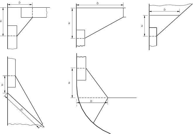
Figure 4.7.2 Diagrammatic arrangements
of stiffener end brackets
Table 4.7.7 Thickness of
brackets
| Bracket
|
Thickness, in mm
|
Limits
|
| Minimum
|
Maximum
|
| With edge
stiffened:
|
|
|
|
| (a) in dry spaces
|

|
6,5
|
12,5
|
| (b) in tanks
|

|
7,5
|
13,5
|
| Unstiffened
brackets
|
|
|
|
| (a) in dry spaces
|

|
7,5
|
-
|
| (b) in tanks
|

|
8,5
|
-
|
7.8.14 Where the stiffening member is lapped on to the bracket, the length of overlap is to
be adequate to provide for the required area of welding. In general, the length of
overlap should be not less than  or the depth of stiffener, whichever is the greater. or the depth of stiffener, whichever is the greater.
7.8.15 Where the free edge of the bracket is hollowed out, it is to be stiffened or
increased in size to ensure that the modulus of the bracket through the throat is
not less than that of the required straight edged bracket.
7.8.16 The arrangement of the connection between the stiffener and the bracket is to be such
that at no point in the connection is the modulus reduced to less than that of the
stiffener with associated plating.
7.8.17 The design of end connections and their supporting structure is to be such as to
provide adequate resistance to rotation and displacement of the joint.
7.8.18 For arrangements where end brackets are not perpendicular to the adjacent plating the
strength of the brackets, in terms of lateral stability, may need to be specially
considered.
7.9 Construction details for primary members
7.9.1 The requirements for section modulus and inertia (if applicable) of
primary members are given in Pt 3, Ch 4, 4 Hull envelope framing. This Section
includes the requirements for proportions, stiffening and construction details for
primary members in dry spaces and in tanks.
7.9.2 The requirements of this sub-Section can be modified where direct calculation
procedures are adopted to analyse the stress distribution in the primary
structure.
7.9.3 The symbols used in this sub-Section are defined as follows:
|
dw |
= |
depth of member web, in mm |
|
k |
= |
higher tensile steel factor, see
Pt 3, Ch 2, 1.2 Steel
|
|
tw |
= |
thickness of member web, in mm |
|
Af |
= |
area of member face plate or flange, in cm2 |
|
Sw |
= |
spacing of stiffeners on member web, or depth of unstiffened web, in
mm. |
7.9.4 Primary members are to be so arranged as to ensure effective continuity of strength,
and abrupt changes of depth or section are to be avoided. Where members abut on both
sides of a bulkhead, or on other members, arrangements are to be made to ensure that
they are in alignment. Primary members in tanks are to form a continuous line of
support and wherever possible, a complete ring system.
7.9.5 The members are to have adequate lateral stability and web stiffening and the
structure is to be arranged to minimise hard spots and other sources of stress
concentration. Openings are to have well rounded corners and smooth edges and are to
be located having regard to the stress distribution and buckling strength of the
panel.
7.9.6 Primary members are to be provided with adequate end fixity by end brackets or
equivalent structure. The design of end connections and their supporting structure
is to be such as to provide adequate resistance to rotation and displacement of the
joint and effective distribution of the load from the member.
7.9.7 Where the primary member is supported by structure which provides only a low degree
of restraint against rotation, the member is generally to be extended for at least
two frame spaces, or equivalent, beyond the point of support before being
tapered.
7.9.8 Where primary members are subject to concentrated loads, particularly if these are
out of line with the member web, additional strengthening could be required.
7.9.12 Primary members are to be supported by tripping brackets. The tripping brackets
supporting asymmetrical sections are to be spaced no more than two secondary frames
apart. The tripping brackets supporting symmetrical sections are to be spaced no
more than four secondary frames apart.
7.9.13 Tripping brackets are also to be fitted at the toes of end brackets and in way of
heavy or concentrated loads such as the heels of pillars.
Table 4.7.8 Minimum thickness of primary members
| Item
|
Requirement
|
| (1) Member web plate, see Note
|
tw = 0,01Sw
but not less than 7 mm in dry spaces and 8 mm
in tanks
|
| (2) Member face plate
|

|
| (3) Deck plating forming the upper flange of
underdeck girders
|

and 10 per cent
greater for hatch side girders.
Width of
plate is to be not less than 700 mm
|
|
Note For primary members having a web depth exceeding 1500 mm,
the arrangement of stiffeners will be individually
considered, and stiffening parallel to the member face plate
could be required.
|
7.9.14 Where the ratio of unsupported width of face plate (or flange) to its thickness
exceeds 16:1, the tripping brackets are to be connected to the face plate and on
members of symmetrical section the brackets are to be fitted on both sides of the
web.
7.9.15 Intermediate secondary members can be welded directly to the web or connected by
lugs.
7.9.16 Where the depth of web of a longitudinal girder at the strength deck within
0,4L amidships exceeds  additional longitudinal web stiffeners are to be
fitted at a spacing not exceeding the value given in (a) or (b) as appropriate, with
a maximum of additional longitudinal web stiffeners are to be
fitted at a spacing not exceeding the value given in (a) or (b) as appropriate, with
a maximum of  for higher tensile steel members. In cases where
this spacing is exceeded, the web thickness is, in general, to be suitably
increased. for higher tensile steel members. In cases where
this spacing is exceeded, the web thickness is, in general, to be suitably
increased.
7.9.17 The arm length of unstiffened end brackets is not to exceed 100tw.
Stiffeners parallel to the bracket face plate are to be fitted where necessary to
ensure that this limit is not exceeded.
7.9.18 Web stiffeners can be flat bars of thickness tw and depth
0,1dw, or 50 mm, whichever is the greater. Alternative
sections of equivalent moment of inertia can be adopted.
7.9.19 Where openings are cut in the web, the depth of opening is not to exceed 25 per cent
of the web depth, and the opening is to be so located that the edges are not less
than 40 per cent of the web depth from the face plate. The length of opening is not
to exceed the web depth or 60 per cent of the secondary member spacing, whichever is
the greater, and the ends of the openings are to be equidistant from the corners of
cut-outs for secondary members. Where larger openings are proposed, the arrangements
and compensation required will be considered.
7.9.20 Openings are to have smooth edges and well-rounded corners.
7.9.21 Cut-outs for the passage of secondary members are to be designed to minimise the
creation of stress concentrations. The breadth of cut-out is to be kept as small as
practicable and the top edge is to be rounded, or the corner radii made as large as
practicable. The extent of direct connection of the web plating, or the scantlings
of lugs or collars, is to be sufficient for the load to be transmitted from the
secondary member.
7.9.22 End connections of primary members are generally to comply with the requirements for
secondary member end connections, taking Z as the section modulus of the
primary member.
7.9.23 The thickness of the bracket is to be not less than that of the primary member web.
The free edge of the bracket is to be stiffened.
7.9.24 Where a deck girder or transverse is connected to a vertical member on the shell or
bulkhead, the scantlings of the latter could be required to be increased to provide
adequate stiffness to resist rotation of the joint.
7.9.25 Where a member is continued over a point of support, such as a pillar or pillar
bulkhead stiffener, the design of the end connection is to be such as to ensure the
effective distribution of the load into the support. Proposals to fit brackets of
reduced scantlings, or alternative arrangements, will be considered.
7.9.26 Connections between primary members forming a ring system are to minimise stress
concentrations at the junctions. Integral brackets are generally to be radiused or
well-rounded at their toes. The arm length of the bracket, measured from the face of
the member, is to be not less than the depth of the smaller member forming the
connection.
7.10 Continuity and alignment
7.10.1 The arrangement of material is to be such as will ensure structural continuity.
Abrupt changes of shape or section, sharp corners and points of stress concentration
are to be avoided.
7.10.2 Where members abut on both sides of a bulkhead or similar structure, care is to be
taken to ensure good alignment.
7.10.3 Pillars and pillar bulkheads are to be fitted in the same vertical line wherever
possible, and elsewhere arrangements are to be made to transmit the out of line
forces satisfactorily. The load at head and heel of pillars is to be effectively
distributed and arrangements are to be made to ensure the adequacy and lateral
stability of the supporting members.
7.10.4 Continuity is to be maintained where primary members intersect and where the members
are of the same depth, a suitable gusset plate is to be fitted.
7.10.5 End connections of structural members are to provide adequate end fixity and
effective distribution of the load into the supporting structure.
7.10.6 The toes of brackets etc. should not land on unstiffened panels of plating. Special
care should be taken to avoid notch effects at the toes of brackets, by making the
toe concave or otherwise tapering it off.
7.10.7 Where primary and/or secondary members are constructed of higher tensile
steel, particular attention is to be paid to the design of the end bracket toes in
order to minimise stress concentrations. Sniped face plates which are welded onto
the edge of primary member brackets are to be carried well around the radiused
bracket toe and are to incorporate a taper not exceeding 1 in 3. Where sniped face
plates are welded adjacent to the edge of primary member brackets, an adequate
cross-sectional area is to be provided through the bracket toe at the end of the
snipe. In general, this area measured perpendicular to the face plate, is to be not
less than 60 per cent of the full cross-sectional area of the face plate, see
Figure 4.7.3 Bracket toe construction.
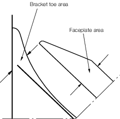
Figure 4.7.3 Bracket toe construction
7.11 Arrangements at intersections of continuous secondary and primary members
7.11.1 Cut-outs for the passage of secondary members through the web of primary members, and
the related collaring arrangements, are to be designed to minimise stress
concentrations around the perimeter of the opening and in the attached hull envelope
or bulkhead plating. The critical shear buckling stress of the panel in which the
cut-out is made is to be investigated. Cut-outs for longitudinals will be required
to have double lugs in areas of high stress, e.g. in way of cross tie ends.
7.11.2 Cut-outs are to have smooth edges, and the corner radii are to be as
large as practicable, with a minimum of 20 per cent of the breadth of the cut-out or
25 mm, whichever is the greater. It is recommended that the web plate connection to
the hull envelope or bulkhead should end in a smooth tapered ‘soft toe’. Recommended
shapes of cut-out are shown in Figure 4.7.5 Cut-outs and
connections,
but consideration will be given to other shapes on the basis of maintaining
equivalent strength and minimising stress concentration. Consideration is to be
given to the provision of adequate drainage and unimpeded flow of air and water when
designing the cut-outs and connection details.
7.11.3 Asymmetrical secondary members are to be connected on the heel side to the primary
member web plate. Additional connection by lugs on the opposite side could be
required.
7.11.4 Symmetrical secondary members are to be connected by lugs on one or both sides, as
necessary.
7.11.5 The cross-sectional areas of the connections are to be determined from the proportion
of load transmitted through each component in association with its appropriate
permissible stress.
7.11.7 This load is to be apportioned between the connections as follows:
- Transmitted through the collar
arrangement:
where Al is derived in
accordance with Pt 3, Ch 4, 7.11 Arrangements at intersections of continuous secondary and primary members 7.11.8 and
is not to be taken as greater than 0,25.
The collar
load factor, Cf, is to be derived as follows:
Symmetrical secondary members
| Cf = 1,85
|
for
Af ≤ 18
|
| Cf = 1,85 -
0,0341(Af -18)
|
for
18 < Af ≤ 40
|
| Cf = 1,1 - 0,01
(Af - 40)
|
for
Af > 40
|
Asymmetrical secondary members
- Transmitted through the primary member web stiffener:

- Where the web stiffener is not connected to the
secondary member, P1, is to be taken equal to P.
Table 4.7.9 Total load
transmitted to connection of secondary members
| Head, h1, in
metres
|
Total load, P in kN,
transmitted to connection
|
| Side and bottom
shell longitudinals
|
(a) In general
P =
10,06(Sw -
s1/2) s1
h1 kN
|
h1 = load height, in metres,
derived in accordance with the following provisions,
but to be taken as not less than the greater of
 or 1,20 m. or 1,20 m.
|
| (a) With
mid-point of span at base line, h1
= 0,8D2
|
| (b) With
mid-point of span at a distance
0,6D2 above base line,
h1 = f
D2
Bf
|
| (c) With
mid-point of span intermediate between (a) and (b).
The value of h1 is to be obtained
by linear interpolation between values from (a) and
(b).
|
| (d) With
mid-point of span higher than
0,6D2 above base line. The value
of h1 is to be obtained by linear
interpolation between the value from (b) and zero at
the level of the deck edge amidships.
|
| Secondary
stiffening members of transverse and longitudinal
bulkheads
h1 =
distance from the mid-point of span to top of tank
but need not exceed
0,8D2
|
| Symbols
|
|
Bf |
= |
bow fullness factor, to be taken
as 1 |
|
f |
= |
load height factor at level
0,6D, see
Table 4.7.10 Load height
factor, f |
|
h1 |
= |
load height, in metres, see
also
Figure 4.7.4 Load height
diagram for framing members |
|
Sw |
= |
spacing of primary members, in
metres |
|
s1 |
= |
spacing of secondary members, in
metres |
|
D2 |
= |
D in metres, but need not
be taken greater than 1,6T
|
|
L1 |
= |
L but need not be taken as
greater than 190 m |
|
Table 4.7.10 Load height
factor, f
|
|
Ship depth, D, in metres
|
| ≤17,5
|
20
|
22,5
|
25
|
27,5
|
30
|
| (1) At and abaft of
0,2L from the forward perpendicular
|
0,6
|
0,6
|
0,582
|
0,556
|
0,535
|
0,517
|
| (2) Forward of 0,15L
from the forward perpendicular
|
0,7
|
0,685
|
0,685
|
0,628
|
0,6
|
0,577
|
|
Note Intermediate values to be obtained by linear
interpolation
|
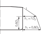
Figure 4.7.4 Load height
diagram for framing members
7.11.8 The effective cross-sectional area A1 of the collar
arrangements is to be taken as the sum of cross-sectional areas of the components of
the connection as follows:
- Direct connection:
- Lug connection:
where
|
f1 |
= |
1,0 for symmetrical secondary member connections |
| = |
 |
|
tw |
= |
thickness of primary member web, in mm |
|
tl |
= |
thickness, in mm, of lug connection, and is to be taken not
greater than the thickness of the adjacent primary member web plate |
|
W |
= |
overall width of the cut-out, in mm |
|
Wl |
= |
width for cut-out asymmetrical to secondary member web, in
mm
See
Figure 4.7.5 Cut-outs and
connections
|
7.11.10 Where a bracket is fitted to the primary member web plate in addition to a connected
stiffener, it is to be arranged on the opposite side to, and in alignment with the
stiffener. The arm length of the bracket is to be not less than the depth of the
stiffener, and its cross-sectional area through the throat of the bracket is to be
included in the calculation of Af.
7.11.11 In general where the primary member stiffener is connected to the
secondary member, it is to be aligned with the web of the secondary member, except
where the face plate of the latter is offset and abutted to the web, in which case
the stiffener connection is to be lapped. Lapped connections of primary member
stiffeners to mild steel bulb plate or rolled angle secondary members may also be
permitted. Where such lapped connections are fitted, particular care is to be taken
to ensure that the primary member stiffener wrap around weld connection is free from
undercut and notches, see also
Pt 3, Ch 4, 7.7 Inspection of welds.
7.11.12 Fabricated longitudinals having the face plate welded to the underside of
the web, leaving the edge of the web exposed, are not recommended for side shell and
longitudinal bulkhead longitudinals. Where it is proposed to fit such sections, a
symmetrical arrangement of connection to transverse members is to be incorporated.
This can be achieved by fitting backing brackets on the opposite side of the
transverse web or bulkhead. The primary member stiffener and backing brackets are to
be lapped to the longitudinal web, see
Pt 3, Ch 4, 7.11 Arrangements at intersections of continuous secondary and primary members 7.11.11.
7.11.13 Collar arrangements are to satisfy the requirements of Pt 3, Ch 4, 7.11 Arrangements at intersections of continuous secondary and primary members 7.11.1 to Pt 3, Ch 4, 7.11 Arrangements at intersections of continuous secondary and primary members 7.11.12 inclusive. In addition, the
weld area of the connections is to be not less than the following:
- Connection of primary member stiffener to the secondary
member:
Aw = 0,25Af or
6,5 cm2 whichever is the greater, corresponding to a weld
factor of 0,34 for the throat thickness
- Connection of secondary member to the web of the primary
member:
Aw =  corresponding to a weld factor of 0,34
in tanks or 0,27 in dry spaces for the throat thickness corresponding to a weld factor of 0,34
in tanks or 0,27 in dry spaces for the throat thickness
where
|
Aw |
= |
weld area, in cm2, and is calculated as total
length of weld, in cm, multiplied by throat thickness, in cm |
|
Af |
= |
cross-sectional area of the primary member web stiffener,
in cm2, in way of connection |
|
Z |
= |
the section modulus, in cm3, of the secondary
member. |
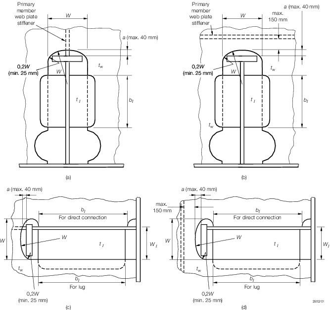
Figure 4.7.5 Cut-outs and
connections
Table 4.7.11 Permissible
stresses
| Item
|
Direct stress, in N/mm2 (see
Notes 1 and 2)
|
Shear stress, in N/mm2 (see Notes
1 and 2)
|
| Primary member web plate stiffener within distance
a of end, see
Figure 4.7.5 Cut-outs and
connections.
|
157
|
-
|
| Welding of
primary member web plate stiffener to secondary member
|
Butted
|
117,7 (double continuous
fillet)
|
-
|
| 157 (automatic deep
penetration)
|
-
|
| Lapped
|
-
|
98,1 See Note
2
|
| Lug or collar
plate and weld
|
Single
|
-
|
98,1
|
| Double
|
|
|
|
|
7.11.15 Alternative arrangements will be considered on the basis of their ability to transmit
load with equivalent effectiveness. Details of the calculations made and testing
procedures are to be submitted.
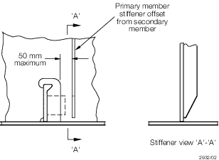
Figure 4.7.6 Arrangement with offset stiffener
7.12 Openings
7.12.1 Manholes, lightening holes and other cut-outs are to be avoided in way of
concentrated loads and areas of high shear. In particular, manholes and similar
openings are not to be cut in vertical or horizontal diaphragm plates in narrow
cofferdams or double plate bulkheads within one-third of their length from either
end, nor in floors or double bottom girders close to their span ends, or below the
heels of pillars, unless the stresses in the plating and the panel buckling
characteristics have been calculated and found satisfactory.
7.12.2 Manholes, lightening holes and other openings are to be suitably framed and stiffened
where necessary.
7.12.3 Air and drain holes, notches and scallops are to be kept at least 200 mm
clear of the toes of end brackets and other areas of high stress. Openings are to be
well rounded with smooth edges. Details of scalloped construction are shown in Figure 4.7.1 Weld dimensions and types.
Closely spaced scallops are not permitted in higher tensile steel members. Widely
spaced air or drain holes may be accepted, provided that they are of elliptical
shape, or equivalent, to minimise stress concentration and are, in general, cut
clear of the weld connection.
7.13 Sheerstrake
7.13.1 Where an angled gunwale is fitted, the top edge of the sheerstrake is to be kept free
of all notches and isolated welded fittings.
7.13.2 Where a rounded gunwale is adopted, the welding of fairlead stools and other fittings
to this plate is to be kept to the minimum, and the design of the fittings is to be
such as to minimise stress concentration.
7.13.3 Arrangements are to ensure a smooth transition from rounded gunwale to angled gunwale
towards the ends of the ship.
7.14 Fittings and attachments
7.14.1 The quality of welding and general workmanship of fittings and attachments are to be
equivalent to that of the main hull structure. Visual examination of all welds is to
be supplemented by non-destructive testing as considered necessary by the Surveyor.
7.14.2 Gutterway bars at the upper deck are to be so arranged that the effect of main hull
stresses on them is minimised.
7.14.3 Minor attachments, such as pipe clips, staging lugs and supports, are generally to be
kept clear of toes of end brackets, corners of openings and similar areas of high
stress. Where connected to asymmetrical stiffeners, the attachments may be in line
with the web providing the fillet weld leg length is clear of the offset face plate
or flange edge. Where this cannot be achieved the attachments are to be connected to
the web, and in the case of flanged stiffeners they are to be kept at least 25 mm
clear of the flange edge. On symmetrical stiffeners, they may be connected to the
web or to the centreline of the face plate in line with the web.
7.14.4 Where necessary in the construction of the ship, lifting lugs can be welded to the
hull plating but they are not to be slotted through. Where they are subsequently
removed, this is to be done by flame or mechanical cutting close to the plate
surface, and the remaining material and welding ground off. After removal the area
is to be carefully examined to ensure freedom from cracks or other defects in the
plate surface.
|